US627172A - John t - Google Patents
John t Download PDFInfo
- Publication number
- US627172A US627172A US627172DA US627172A US 627172 A US627172 A US 627172A US 627172D A US627172D A US 627172DA US 627172 A US627172 A US 627172A
- Authority
- US
- United States
- Prior art keywords
- circuit
- telephone
- coin
- armatures
- chute
- Prior art date
- Legal status (The legal status is an assumption and is not a legal conclusion. Google has not performed a legal analysis and makes no representation as to the accuracy of the status listed.)
- Expired - Lifetime
Links
Images
Classifications
-
- H—ELECTRICITY
- H04—ELECTRIC COMMUNICATION TECHNIQUE
- H04M—TELEPHONIC COMMUNICATION
- H04M17/00—Prepayment of wireline communication systems, wireless communication systems or telephone systems
- H04M17/02—Coin-freed or check-freed systems, e.g. mobile- or card-operated phones, public telephones or booths
- H04M17/023—Circuit arrangements
Definitions
- This invention relates to toll apparatus for telephone pay-stations and it consists in the construction and arrangement of parts hereinafter fully set forth, and pointed out particularly in the claims.
- the object of the invention is to provide means for connection with an ordinary subscribers telephone or the instrument at a public pay-station, whereby the operator at the central station may know that a person at a telephone or substation wishing to talk with a person at a second substation has deposited in the apparatus a coin in payment for the services before connection between said parties is made, and a further arrangement whereby the operator at the central station may readily discharge the coin after receiving the signal caused by its insertion in the apparatus so as to leave the signal-circuitopen and the parts in position for 'a-sncceeding operation and at the same time-relieve the talking-circuit of all disturbance from said signaling-circuit while the talking-circuit is in use.
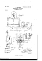
- FIG. 1 is a general view of a cabinet containing an ordinary telephone and my improved coin-actuated signaling apparatus.
- Fig.2 is a diagram matical view of the ordinary telephone-circuit with which my improved signaling-circuit is connected by means of an induction-coil, together with the operators instrument, and an auxiliary circuit bridged" onto the main line through which a generatorcurrent may be passed for the purpose of ac tuating electrically mechanism to discharge the coin after the signal, caused bythe insertion of said coin, has been conveyed to the operator.
- Fig. 2 is a diagram matical view of the ordinary telephone-circuit with which my improved signaling-circuit is connected by means of an induction-coil, together with the operators instrument, and an auxiliary circuit bridged" onto the main line through which a generatorcurrent may be passed for the purpose of ac tuating electrically mechanism to discharge the coin after the signal, caused bythe insertion of said coin, has been conveyed to the operator.
- 3 is a large detail in section of a portion of the coin-chute and of the pivoted contact-armatures which project into said chute and are adapted to arrest and support a coin between their opposed ends to complete a circuit therethrough and maintain said coin in contact therewith until discharged by a movement of said armatnres produced by the energizing of their respective magnets.
- A designates a cabinet,which may be of any suitable construction and upon which is mounted the ordinary telephone instrument B.
- a slot 0. In the inclined top of said cabinet is a slot 0., which communicates with the coinchute within the cabinet, said cabinet also containing the necessary wiring and the signaling mechanism, as hereinafter explained.
- FIG. 2 illustrates the ordinary telephone instrument B, provided with i the usual line-circuit b I), connected with the operators instrument 0. It will also be understood that there is connected with the telephone-line the usual annunciator-cireuit. (Not shown.)
- D designates a generator whose line at one end is connected at c with the telephone-line and at the other end is provided with a contact-terminal d.
- the line b after passing through the operators instrument is provided with a contact-terminal d.
- E designates a switch having at its ends contact-pins 6, adapted to close the circuit between the contact-terminals d and d of the respective lines.
- the closing of the circuit at d throws the generator onto the telephoneline, while the closing of the circuit at cl places the operator in circuit with the subscribers instrument or station E. t
- F designates the coin-ch11 te, which consists of a vertical way communicating with the slot at in the top of the cabinet, through which the coin is adapted to be passed.
- Attached to said chute are the insulated brackets f.
- Pivoted to said brackets are the armatures g of the electromagnets it.
- These armatures are provided with angle end portions 0, which project inwardly through slots t in the oppotherein, so, as to arrest said coin in its passage down said chute and hold it in contact with thmopposed ends thereof, as clearly shown in Fig. 3, in which view G designates the coin.
- said coin bridges between the points of said armatures and closes the circuit between them, the complementary portion of which circuit is formed by the lines k, in which is located a battery II, and which forms the primary side of the induction-coil I, the secondary side of said coil being formed by line b of the telephone-circuit.
- auxiliary circuit m Bridged onto the main line is an auxiliary circuit m, in which are included the electromagnets h. i
- the subscriber 13 calls the operator in the usual manner, when the operator throws the switch E to the answering or listening position thereby closing the telephone-circuit at d,the talkingcurrentin said line being supplied by the battery J through the primary side of the induction-coil I.
- the operator ascertains the substation called, and when connections have been properly made subscriber at B is requested to place the required coin in the slot a.
- a telephone toll apparatus the combination with the telephone-circuit, of a coinchute, two pivoted armatu res having end portions projecting into said chute from opposite sides, said armatures forming the open terminals of a signaling-circuit, two electromagnets included in a circuitbridged onto the telephone-circuit, and a switch for connecting a source of electricity with the circuit of said electromagnets to energize said magnets and attract said armatures.
- a telephone toll apparatus the combination with a telephone-circuit, the pivoted armatures projecting into the coin-chute from opposite sides and forming the terminals of a normally open signaling-circuit, two electromagnets adapted to attract said armatures included in a line bridged onto the telephoneline, a source of electricityin the limb of the telephone-line, and a switch for closing a circuit including said source of electricity and the bridged line containing said electromagnets.
- a telephone toll apparatus the combination with a telephone-line, a coin-chute, two pivoted armatures projecting into said chute from opposite sides so as to arrest a coin in its passage through said chute, a signalingcircuit of which said armatures form the terminals, electromagnets adapted to actuate said armatures to withdraw their ends from said chute, said armatures being included with a source of electricity in a normally open circuit of which said telephone-line forms a complementary portion, and a switch for closing said circuit through said source of electricity and said electromagnets.
Landscapes
- Engineering & Computer Science (AREA)
- Computer Networks & Wireless Communication (AREA)
- Computer Security & Cryptography (AREA)
- Signal Processing (AREA)
- Prepayment Telephone Systems (AREA)
Description
'No. s27,|72. Patented June 20, I899. J. T. BELANGER.
TELEPHONE TOLL APPARATUS.
(Application filed Apr. 3, 1899.)
(No Model.)
WITNESSES.
.Attorneys.
NITED STATES PATENT OFFICE.
JOHN T. BELANGER, OF'DETROIT, MICHIGAN, ASSIGNOR OF ONE-HALF TO FRANK H. CLARK, OF SAME PLACE.
TELEPHONE TOEL APPARATUS.
SPECIFICATION forming part of Letters Patent No. 627,172, dated June 20, 1899.
Application filed April 3, 1899. Serial No. 711,517. (No model.)
To all whom it ntcty concern:
- Be it known that 1, JOHN T. BELANGER, a citizen ofthe United States, residing at Detroit, in the county of Wayne, State of Michigan, have invented certain new and useful Improvements in Telephone Toll Apparatus; and I do hereby declare the following to be a full, clear, and exact description of the illvention, such as will enable others skilled in the art to which it appertains to make and use the same, reference being had to the accompanying drawings, and to the letters of reference marked thereon, which form a part of this specification.
This invention relates to toll apparatus for telephone pay-stations and it consists in the construction and arrangement of parts hereinafter fully set forth, and pointed out particularly in the claims.
The object of the invention is to provide means for connection with an ordinary subscribers telephone or the instrument at a public pay-station, whereby the operator at the central station may know that a person at a telephone or substation wishing to talk with a person at a second substation has deposited in the apparatus a coin in payment for the services before connection between said parties is made, and a further arrangement whereby the operator at the central station may readily discharge the coin after receiving the signal caused by its insertion in the apparatus so as to leave the signal-circuitopen and the parts in position for 'a-sncceeding operation and at the same time-relieve the talking-circuit of all disturbance from said signaling-circuit while the talking-circuit is in use. This object is attained by the association and arrangement of parts illustrated in the accompanying drawings, in which Figure 1 is a general view of a cabinet containing an ordinary telephone and my improved coin-actuated signaling apparatus. Fig.2 is a diagram matical view of the ordinary telephone-circuit with which my improved signaling-circuit is connected by means of an induction-coil, together with the operators instrument, and an auxiliary circuit bridged" onto the main line through which a generatorcurrent may be passed for the purpose of ac tuating electrically mechanism to discharge the coin after the signal, caused bythe insertion of said coin, has been conveyed to the operator. Fig. 3 is a large detail in section of a portion of the coin-chute and of the pivoted contact-armatures which project into said chute and are adapted to arrest and support a coin between their opposed ends to complete a circuit therethrough and maintain said coin in contact therewith until discharged by a movement of said armatnres produced by the energizing of their respective magnets.
Referring to the letters of reference, A designates a cabinet,which may be of any suitable construction and upon which is mounted the ordinary telephone instrument B. In the inclined top of said cabinet is a slot 0., which communicates with the coinchute within the cabinet, said cabinet also containing the necessary wiring and the signaling mechanism, as hereinafter explained.
The diagram in Fig. 2 illustrates the ordinary telephone instrument B, provided with i the usual line-circuit b I), connected with the operators instrument 0. It will also be understood that there is connected with the telephone-line the usual annunciator-cireuit. (Not shown.)
D designates a generator whose line at one end is connected at c with the telephone-line and at the other end is provided with a contact-terminal d. The line b after passing through the operators instrument is provided with a contact-terminal d.
E designates a switch having at its ends contact-pins 6, adapted to close the circuit between the contact-terminals d and d of the respective lines. The closing of the circuit at d throws the generator onto the telephoneline, while the closing of the circuit at cl places the operator in circuit with the subscribers instrument or station E. t
F designates the coin-ch11 te, which consists of a vertical way communicating with the slot at in the top of the cabinet, through which the coin is adapted to be passed. Attached to said chute are the insulated brackets f. Pivoted to said brackets are the armatures g of the electromagnets it. These armatures are provided with angle end portions 0, which project inwardly through slots t in the oppotherein, so, as to arrest said coin in its passage down said chute and hold it in contact with thmopposed ends thereof, as clearly shown in Fig. 3, in which view G designates the coin. As will be seen, said coin bridges between the points of said armatures and closes the circuit between them, the complementary portion of which circuit is formed by the lines k, in which is located a battery II, and which forms the primary side of the induction-coil I, the secondary side of said coil being formed by line b of the telephone-circuit.
Bridged onto the main line is an auxiliary circuit m, in which are included the electromagnets h. i
In the operation of this device the subscriber 13 calls the operator in the usual manner, when the operator throws the switch E to the answering or listening position thereby closing the telephone-circuit at d,the talkingcurrentin said line being supplied by the battery J through the primary side of the induction-coil I. The operator ascertains the substation called, and when connections have been properly made subscriber at B is requested to place the required coin in the slot a. Upon the insertion of said coin it travels down the chute F and bridges between the inwardly-projecting ends of the armatures g, thereby closing the circuit formed by the lines 70 70 and inducing a current in the lines I) and b, which causes a click or sound in the operators instrument and serves as a signal to advise her that a subscriber or patron at instrument B has inserted the coin as requested. The operator then moves the switch so as to close the generator-circ uit at d,thereby throwing the generator-current onto the lines I) b and the bridged line m, energizing the electromagnets h, and attracting the armatures g, as shown by dotted lines in Fig. 2, permitting the coin G, which had closed the circuit between them, to drop into the box K at the bottom of said chute. The generator-circuit is then opened by returning the switch to its normal position, when the retracting-springs 25 return said armatures so as to cause their ends to project into the chute in position for a succeeding operation. Connection is then properly made between the subscriber and the station called by means not shown, but in a manner well understood in the art.
It will be understood thata number of signaling-circuits may be arranged containing varying signals to denote various denominations of coin placed in the apparatus; but all of such signaling-circuits will be closed in the manner herein specified and need not therefore be particularly set forth.
Havingthus fully set forth this invention,
what is claimed is- 1. In a telephone toll apparatus, the combination of the telephone-circuit, the signalin g-circuit including a movable contact, a circuit bridged onto the telephone-circuit independent of said signaling-circuit and containing an electromagnet adapted to actuate said movable contact of the signaling-circuit and means for energizing said electroinagnet, substantially as set forth.
2. In a telephone toll apparatus, the combination with the telephone-circuit, of a coinchute, two pivoted armatu res having end portions projecting into said chute from opposite sides, said armatures forming the open terminals of a signaling-circuit, two electromagnets included in a circuitbridged onto the telephone-circuit, and a switch for connecting a source of electricity with the circuit of said electromagnets to energize said magnets and attract said armatures.
3. In a telephone toll apparatus, the combination with a telephone-circuit, the pivoted armatures projecting into the coin-chute from opposite sides and forming the terminals of a normally open signaling-circuit, two electromagnets adapted to attract said armatures included in a line bridged onto the telephoneline, a source of electricityin the limb of the telephone-line, and a switch for closing a circuit including said source of electricity and the bridged line containing said electromagnets.
4. In a telephone toll apparatus, the combination with a telephone-line, a coin-chute, two pivoted armatures projecting into said chute from opposite sides so as to arrest a coin in its passage through said chute, a signalingcircuit of which said armatures form the terminals, electromagnets adapted to actuate said armatures to withdraw their ends from said chute, said armatures being included with a source of electricity in a normally open circuit of which said telephone-line forms a complementary portion, and a switch for closing said circuit through said source of electricity and said electromagnets.
In testimony whereof I sign this specification in the presence of two Witnesses.
JOHN T. BELANGER.
Witnesses:
F. J. PEDDIE, FRANK H. CLARKE.
Publications (1)
| Publication Number | Publication Date |
|---|---|
| US627172A true US627172A (en) | 1899-06-20 |
Family
ID=2695772
Family Applications (1)
| Application Number | Title | Priority Date | Filing Date |
|---|---|---|---|
| US627172D Expired - Lifetime US627172A (en) | John t |
Country Status (1)
| Country | Link |
|---|---|
| US (1) | US627172A (en) |
-
0
- US US627172D patent/US627172A/en not_active Expired - Lifetime
Similar Documents
| Publication | Publication Date | Title |
|---|---|---|
| US627172A (en) | John t | |
| US912397A (en) | Check-controlled device. | |
| US751081A (en) | Coin-controlled telephone apparatus | |
| US774265A (en) | Toll-collecting appliance for telephone pay-stations. | |
| US2750447A (en) | Paystation telephone system | |
| US650488A (en) | Toll-collecting appliance for telephone pay-stations. | |
| US860647A (en) | Coin-collecting apparatus for telephone-exchanges. | |
| US665874A (en) | Apparatus for telephone toll-lines. | |
| US1160994A (en) | Pay-station telephone system. | |
| US679068A (en) | Apparatus for telephone-lines. | |
| US793389A (en) | Telephone service-meter. | |
| US651817A (en) | Telephone toll apparatus. | |
| US845111A (en) | Circuit for coin-collectors. | |
| US645958A (en) | Telephone-system. | |
| US677807A (en) | Coin-collector for telephone toll-lines. | |
| US424993A (en) | Telephone toll-box and connection-register | |
| US766192A (en) | Measured-service system for party-lines. | |
| US669900A (en) | Telephone service-meter and circuit. | |
| US980690A (en) | Telephone-rent-collecting device. | |
| US880708A (en) | Telephone toll apparatus. | |
| US848378A (en) | Apparatus for telephone toll-lines. | |
| US690289A (en) | Telephone-meter. | |
| US1349373A (en) | Measured-service telephone system | |
| US1215331A (en) | Telephone toll system. | |
| US919409A (en) | Clear-out system for telephone-switchboards. |