US6269638B1 - Air bubble powered rotary driving apparatus - Google Patents
Air bubble powered rotary driving apparatus Download PDFInfo
- Publication number
- US6269638B1 US6269638B1 US09/306,923 US30692399A US6269638B1 US 6269638 B1 US6269638 B1 US 6269638B1 US 30692399 A US30692399 A US 30692399A US 6269638 B1 US6269638 B1 US 6269638B1
- Authority
- US
- United States
- Prior art keywords
- gas
- rotary driving
- driving apparatus
- turbine wheels
- screw
- Prior art date
- Legal status (The legal status is an assumption and is not a legal conclusion. Google has not performed a legal analysis and makes no representation as to the accuracy of the status listed.)
- Expired - Fee Related
Links
Images


Classifications
-
- F—MECHANICAL ENGINEERING; LIGHTING; HEATING; WEAPONS; BLASTING
- F03—MACHINES OR ENGINES FOR LIQUIDS; WIND, SPRING, OR WEIGHT MOTORS; PRODUCING MECHANICAL POWER OR A REACTIVE PROPULSIVE THRUST, NOT OTHERWISE PROVIDED FOR
- F03B—MACHINES OR ENGINES FOR LIQUIDS
- F03B17/00—Other machines or engines
-
- F—MECHANICAL ENGINEERING; LIGHTING; HEATING; WEAPONS; BLASTING
- F01—MACHINES OR ENGINES IN GENERAL; ENGINE PLANTS IN GENERAL; STEAM ENGINES
- F01D—NON-POSITIVE DISPLACEMENT MACHINES OR ENGINES, e.g. STEAM TURBINES
- F01D1/00—Non-positive-displacement machines or engines, e.g. steam turbines
- F01D1/34—Non-positive-displacement machines or engines, e.g. steam turbines characterised by non-bladed rotor, e.g. with drilled holes
- F01D1/38—Non-positive-displacement machines or engines, e.g. steam turbines characterised by non-bladed rotor, e.g. with drilled holes of the screw type
-
- Y—GENERAL TAGGING OF NEW TECHNOLOGICAL DEVELOPMENTS; GENERAL TAGGING OF CROSS-SECTIONAL TECHNOLOGIES SPANNING OVER SEVERAL SECTIONS OF THE IPC; TECHNICAL SUBJECTS COVERED BY FORMER USPC CROSS-REFERENCE ART COLLECTIONS [XRACs] AND DIGESTS
- Y02—TECHNOLOGIES OR APPLICATIONS FOR MITIGATION OR ADAPTATION AGAINST CLIMATE CHANGE
- Y02E—REDUCTION OF GREENHOUSE GAS [GHG] EMISSIONS, RELATED TO ENERGY GENERATION, TRANSMISSION OR DISTRIBUTION
- Y02E10/00—Energy generation through renewable energy sources
- Y02E10/20—Hydro energy
Definitions
- the invention relates to an apparatus for converting discharged air into a rotary force.
- Air blasts are used in many ways such as for cleaning and compressing. However, few concepts and technologies have been developed for using the air once blasted for other purposes.
- the object of this invention is to generate a rotary driving force by the use of ascending air bubbles formed by injecting air into a liquid.
- the rotary driving apparatus comprises at least one rotatably mounted turbine wheel or screw submerged in a liquid, preferably water, and a gas introducing means for introducing gas into the liquid, arranged below the turbine wheel or screw, for forming gas bubbles which contact the vanes of the turbine wheel or screw surface whereby the turbine wheel or screw surface is caused to rotate.
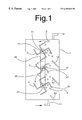
- FIG. 1 is a side elevation of an embodiment of a rotary driving apparatus which comprises turbine wheels which rotate about a horizontal axis.
- FIG. 2 is a side elevation of an embodiment of the rotary driving apparatus which comprises a screw arranged to rotate about a vertical axis.
- FIG. 3 is a perspective view of a turbine wheel of the embodiment shown in FIG. 1 .
- FIG. 4 is a cross-sectional side elevation view of a further embodiment the screw arrangement of the invention.
- FIG. 5 is a schematic illustration of an embodiment of the invention where the gas is passed through tanks arranged in series which have arranged therein a rotary driving apparatus.
- FIG. 6 is a view in partial cross-section of the embodiment of FIG. 2 having propellers or turbine wheels instead of a screw flight.
- the basic operating principle of this invention is to convert the energy of ascending gas (preferably air) bubbles formed by gas introduced into a liquid.
- the gas is introduced into the liquid below the apparatus in rotary motion.
- the apparatus comprises multiple turbine wheels 2 rotatable with a horizontal shaft 22 supported in vessel 1 arranged to be turned by ascending gas bubbles 5 .
- Multiple vanes 21 of each turbine wheel 2 are curved or bent so that the ascending gas bubbles 5 contact the inner enclosed surface of each vane.
- the rotating turbine wheel 2 and a gas inlet 11 are preferably arranged so that the ascending gas bubbles 5 preferably contact the downwardly opened space defined by one of the vanes 21 with an upwardly projecting top surface.
- the rotary turbine wheels 2 can be provided in multiples to increase the efficiency of conversion of the energy of the ascending gas bubbles 5 into rotary motion.
- Shaft 22 supporting the turbine wheels 2 preferably have mounted thereon, gears or pulleys 41 which, through a belt 42 (shown), are arranged to provide a single rotary motion which comprises the sum of the forces from the individual turbine wheels.
- the apparatus shown in FIG. 2 comprises a rotatable member 3 having a shaft 31 that is substantially vertically arranged and supported by the top 7 and bottom 8 ends of a liquid tank 1 .
- the rotatable member 3 is rotated by ascending gas bubbles 5 that contact the surface of the screw flight 6 to thereby generate a rotary driving force.
- multiple turbine wheels or propellers arranged one above the other can be mounted on shaft 31 as shown in FIG. 6 .
- the rotatable member 3 may be of either a propeller or turbine type (as shown in FIG. 6) or a screw conveyor type as shown in FIG. 2 .
- a propeller or turbine wheel When a propeller or turbine wheel is arranged on vertical shaft 31 , they are preferably provided in multiples to insure efficient conversion of the energy of the ascending gas bubbles 5 into rotary motion.
- FIG. 1 shows an embodiment of the invention having the structure described above.
- Projecting plates 13 to guide the gas bubbles 5 toward the vanes 21 are provided to project obliquely upward on the inner side of the liquid tank where the gas bubbles 5 ascend.
- This projecting plate decreases the percentage of gas bubbles 5 that pass through the gap between the side wall of the tank and the vanes 21 without contacting the vanes 21 and, therefore, without contributing to the generation of the rotary driving force.
- FIG. 3 shows an embodiment of the turbine wheel 2 of the apparatus shown in FIG. 1 .
- Side plates 23 are provided on both sides of each vane 21 mounted on shaft 22 of the rotating turbine 2 .
- the side plates 23 keep the gas from the bubbles 5 , trapped by the vane 21 , from escaping from both sides thereof.
- the gas from bubbles 5 thus confined contribute to the upward motion of the turbine wheel 2 and a more efficient evolution of rotary motion.
- FIG. 4 shows a third embodiment that has holding plates 32 projecting obliquely downward to trap the air bubbles 5 below the screw 3 .
- the plates 32 may be arranged obliquely to the downward facing surface of the screw flight.
- the ascending bubbles 5 held below the screw 3 exert a rotary force on the under surface of not only the screw 3 but also the holding plates 32 .
- the holding plates 32 make a contribution to the efficient evolution of rotary force in the structure ( 2 ) described above.
- Diverters 13 are placed to direct the rising gas bubbles toward the screw.
- the gas can be passed in series through multiple liquid tanks as shown in FIG. 4 in which an apparatus of the invention is arranged.
- Gas inlets 11 and gas outlets 12 on the individual tanks are interconnected with each other.
- the gas still retaining some energy at the top of a tank is led from the gas outlet 12 to the gas inlet 11 of an adjoining liquid tank to generate rotary motion.
- the use of liquid tanks 1 in series permits more effective use of gas energy in the generation of rotary motion.
- FIG. 6 shows turbine wheels 9 arranged on shaft 31 mounted vertically in vessel 1 with gas inlet 11 and gas outlet 12 .
- Upper turbine wheel 9 is shown cut away to show the inclined vanes 15 and gas passages 16 arranged in the turbine wheel. Plates 13 project obliquely into vessel 1 to guide the flow of gas bubbles 5 away from the walls of vessel 1 to the operating portion of turbine wheels 9 .
- Turbine wheels 9 can be designed to approach the walls 5 of vessel 1 more closely so that plates 13 can be eliminated or the opening 6 substantially increased in size.
- Rotary motion can be taken off from pulley 17 mounted on shaft 31 .
- Shaft 31 is mounted on vessel 1 with shaft sealing means 34 and is supported by radial bearing 35 and thrust and radial bearings 36 .
- the means for mounting shafts 31 and 22 in the apparatus are well known and will not be illustrated here.
- the apparatus can be designed to be used suspended in open water to use the energy from underwater gas vents or in large tanks.
- this invention permits efficient conversion of the energy of discharged gas into rotary motion.
- the rotary motion thus obtained can be used for power generation and other forms of a power source.
Landscapes
- Engineering & Computer Science (AREA)
- Mechanical Engineering (AREA)
- General Engineering & Computer Science (AREA)
- Chemical & Material Sciences (AREA)
- Combustion & Propulsion (AREA)
- Other Liquid Machine Or Engine Such As Wave Power Use (AREA)
- Hydraulic Turbines (AREA)
Abstract
A rotary driving apparatus using air bubbles comprises multiple rotating turbine wheels arranged one above the other and supported to be horizontally rotatable supported by sides of a tank having a gas inlet at the bottom thereof and a gas outlet at the top thereof, multiple vanes of each turbine wheel being curved or bent so that ascending gas bubbles contact the inner enclosed surface of each vane, and the multiple turbine wheels are interlocked to each other by means of gears, a chain or a belt. A rotary driving apparatus using gas bubbles also comprises one or more screws rotatably supported at the top and bottom ends of a tank having a gas inlet at the bottom thereof and a gas outlet at the top thereof, the screw or screws being placed where ascending gas bubbles contact the screw flight. The gas is introduced into a liquid and the buoyancy of the resulting gas bubbles is used to generate a rotary driving force.
Description
The invention relates to an apparatus for converting discharged air into a rotary force.
Air blasts are used in many ways such as for cleaning and compressing. However, few concepts and technologies have been developed for using the air once blasted for other purposes.
The object of this invention is to generate a rotary driving force by the use of ascending air bubbles formed by injecting air into a liquid.
According to the present invention, the rotary driving apparatus comprises at least one rotatably mounted turbine wheel or screw submerged in a liquid, preferably water, and a gas introducing means for introducing gas into the liquid, arranged below the turbine wheel or screw, for forming gas bubbles which contact the vanes of the turbine wheel or screw surface whereby the turbine wheel or screw surface is caused to rotate.
In a preferred embodiment, the rotary driving apparatus which uses air bubbles for rotation comprises a multiplicity of rotatable turbine wheels arranged one above the other supported to be rotatable about a horizontal axis by sides of a liquid tank having an air inlet at the bottom thereof and an air outlet at the top thereof; multiple vanes of each turbine wheel being curved or bent so that ascending air bubbles contact the inner enclosed surface of each vane, the multiple turbine wheels or propellers being interlocked to each other by means of gears, a chain or a belt, and the like.
In a second preferred embodiment, the rotary driving apparatus which uses air bubbles for rotation comprises at least one vertically arranged screw turbine wheel or propeller having a shaft rotatably supported at the top and the bottom by the top and bottom ends of a liquid holding tank, the liquid holding tank having an air inlet at the bottom thereof and an air outlet at the top thereof, the screw turbine wheel or propeller being arranged so that ascending bubbles contact a surface of the screw, turbine wheel or propeller.
FIG. 1 is a side elevation of an embodiment of a rotary driving apparatus which comprises turbine wheels which rotate about a horizontal axis.
FIG. 2 is a side elevation of an embodiment of the rotary driving apparatus which comprises a screw arranged to rotate about a vertical axis.
FIG. 3 is a perspective view of a turbine wheel of the embodiment shown in FIG. 1.
FIG. 4 is a cross-sectional side elevation view of a further embodiment the screw arrangement of the invention.
FIG. 5 is a schematic illustration of an embodiment of the invention where the gas is passed through tanks arranged in series which have arranged therein a rotary driving apparatus.
FIG. 6 is a view in partial cross-section of the embodiment of FIG. 2 having propellers or turbine wheels instead of a screw flight.
As will be evident from the description above, the basic operating principle of this invention is to convert the energy of ascending gas (preferably air) bubbles formed by gas introduced into a liquid. Preferably, the gas is introduced into the liquid below the apparatus in rotary motion.
As shown in FIG. 1, the apparatus comprises multiple turbine wheels 2 rotatable with a horizontal shaft 22 supported in vessel 1 arranged to be turned by ascending gas bubbles 5. Multiple vanes 21 of each turbine wheel 2 are curved or bent so that the ascending gas bubbles 5 contact the inner enclosed surface of each vane.
The gas bubbles 5 caught by the inner surface of the curved or bent vanes 21 of turbine wheel 2 cause the turbine wheel 2 to rotate with the horizontal shaft 22.
The rotating turbine wheel 2 and a gas inlet 11 are preferably arranged so that the ascending gas bubbles 5 preferably contact the downwardly opened space defined by one of the vanes 21 with an upwardly projecting top surface.
Even if the air inlet 11 is arranged in a position such that the gas bubbles do not preferably contact a downwardly open space of vane 21 of turbine wheel 2, the gas bubbles 5 move upward along the downwardly slanted surface of the vane 21. Even then, the rotating turbine wheel 2 rotates with the one side thereof which captures the gas bubbles 5 moving upward because the ascending force of the gas bubbles working on the downwardly projecting vane is weaker than the force working on the downwardly opened vane.
The rotary turbine wheels 2 can be provided in multiples to increase the efficiency of conversion of the energy of the ascending gas bubbles 5 into rotary motion.
The apparatus shown in FIG. 2 comprises a rotatable member 3 having a shaft 31 that is substantially vertically arranged and supported by the top 7 and bottom 8 ends of a liquid tank 1. The rotatable member 3 is rotated by ascending gas bubbles 5 that contact the surface of the screw flight 6 to thereby generate a rotary driving force. Instead of a screw flight 6, multiple turbine wheels or propellers arranged one above the other can be mounted on shaft 31 as shown in FIG. 6.
The rotatable member 3 may be of either a propeller or turbine type (as shown in FIG. 6) or a screw conveyor type as shown in FIG. 2. When a propeller or turbine wheel is arranged on vertical shaft 31, they are preferably provided in multiples to insure efficient conversion of the energy of the ascending gas bubbles 5 into rotary motion.
FIG. 1 shows an embodiment of the invention having the structure described above. Projecting plates 13 to guide the gas bubbles 5 toward the vanes 21 are provided to project obliquely upward on the inner side of the liquid tank where the gas bubbles 5 ascend.
This projecting plate decreases the percentage of gas bubbles 5 that pass through the gap between the side wall of the tank and the vanes 21 without contacting the vanes 21 and, therefore, without contributing to the generation of the rotary driving force.
FIG. 3 shows an embodiment of the turbine wheel 2 of the apparatus shown in FIG. 1. Side plates 23 are provided on both sides of each vane 21 mounted on shaft 22 of the rotating turbine 2.
The side plates 23 keep the gas from the bubbles 5, trapped by the vane 21, from escaping from both sides thereof. The gas from bubbles 5 thus confined contribute to the upward motion of the turbine wheel 2 and a more efficient evolution of rotary motion.
FIG. 4 shows a third embodiment that has holding plates 32 projecting obliquely downward to trap the air bubbles 5 below the screw 3. The plates 32 may be arranged obliquely to the downward facing surface of the screw flight.
The ascending bubbles 5 held below the screw 3 exert a rotary force on the under surface of not only the screw 3 but also the holding plates 32. The holding plates 32 make a contribution to the efficient evolution of rotary force in the structure (2) described above. Diverters 13 are placed to direct the rising gas bubbles toward the screw.
As shown in FIG. 5, the gas can be passed in series through multiple liquid tanks as shown in FIG. 4 in which an apparatus of the invention is arranged. Gas inlets 11 and gas outlets 12 on the individual tanks are interconnected with each other. The gas still retaining some energy at the top of a tank is led from the gas outlet 12 to the gas inlet 11 of an adjoining liquid tank to generate rotary motion. The use of liquid tanks 1 in series permits more effective use of gas energy in the generation of rotary motion.
FIG. 6 shows turbine wheels 9 arranged on shaft 31 mounted vertically in vessel 1 with gas inlet 11 and gas outlet 12. Upper turbine wheel 9 is shown cut away to show the inclined vanes 15 and gas passages 16 arranged in the turbine wheel. Plates 13 project obliquely into vessel 1 to guide the flow of gas bubbles 5 away from the walls of vessel 1 to the operating portion of turbine wheels 9. Turbine wheels 9 can be designed to approach the walls 5 of vessel 1 more closely so that plates 13 can be eliminated or the opening 6 substantially increased in size. Rotary motion can be taken off from pulley 17 mounted on shaft 31. Shaft 31 is mounted on vessel 1 with shaft sealing means 34 and is supported by radial bearing 35 and thrust and radial bearings 36.
The means for mounting shafts 31 and 22 in the apparatus are well known and will not be illustrated here. The apparatus can be designed to be used suspended in open water to use the energy from underwater gas vents or in large tanks.
As is obvious from the above, this invention permits efficient conversion of the energy of discharged gas into rotary motion.
The rotary motion thus obtained can be used for power generation and other forms of a power source.
Claims (9)
1. A rotary driving apparatus which comprises: at least one screw flight mounted on a shelf rotatably supported on a vertical axis said shaft having means for taking off power in the form of rotary motion, a gas inlet arranged at or below the screw flight and a gas outlet arranged above the screw flight, the gas inlet facing a downward facing surface of the screw flight.
2. The rotary driving apparatus according to claim 1 which further comprises plates projecting obliquely upward to gas bubbles toward the screw flight.
3. The rotary driving apparatus of claim 1 wherein the screw flight comprises plates projecting from the downward facing surface of the screw flight.
4. The apparatus of claim 3 which further comprises plates projecting obliquely upward to direct gas bubbles toward the screws.
5. The rotary driving apparatus of claim 1 comprising at least two tanks comprising the screw flights arranged to provide flow of the gas through at least two tanks in series.
6. A rotary driving apparatus which comprises: a plurality of turbine wheels, arranged one above the other on a shaft rotatably supported on a vertical axis said shaft having means for taking off power in the form of rotary motion, a gas inlet arranged below the turbine wheels and a gas outlet arranged above the turbine wheels.
7. The rotary driving apparatus according to claim 6, in which a projecting plate is provided between each of the turbine wheels.
8. The apparatus of claim 6 further comprising plates projecting obliquely upward to direct gas bubbles toward the turbine wheels.
9. The rotary driving apparatus of claim 6 comprising at least two tanks comprising the turbine wheels arranged to provide flow of the gas through at least two tanks in series.
Applications Claiming Priority (2)
| Application Number | Priority Date | Filing Date | Title |
|---|---|---|---|
| JP10127427A JPH11324891A (en) | 1998-05-11 | 1998-05-11 | Rotation driving device using bubble |
| JP10-127427 | 1998-05-11 |
Publications (1)
| Publication Number | Publication Date |
|---|---|
| US6269638B1 true US6269638B1 (en) | 2001-08-07 |
Family
ID=14959699
Family Applications (1)
| Application Number | Title | Priority Date | Filing Date |
|---|---|---|---|
| US09/306,923 Expired - Fee Related US6269638B1 (en) | 1998-05-11 | 1999-05-07 | Air bubble powered rotary driving apparatus |
Country Status (2)
| Country | Link |
|---|---|
| US (1) | US6269638B1 (en) |
| JP (1) | JPH11324891A (en) |
Cited By (19)
| Publication number | Priority date | Publication date | Assignee | Title |
|---|---|---|---|---|
| US20050061590A1 (en) * | 2001-12-28 | 2005-03-24 | Sram Corporation | Master cylinder lever for a hydraulic disc brake having a backpack reservoir |
| US6945042B1 (en) | 2004-08-27 | 2005-09-20 | Walckner James R | System for generating fluid movement |
| US20070090145A1 (en) * | 2005-10-25 | 2007-04-26 | Metso Paper, Inc. | Vacuum Belt Conveyor of a Web Forming Machine for Transferring a Threading Tail |
| KR100744194B1 (en) * | 2005-12-12 | 2007-08-01 | 주식회사리젠코리아 | Spiral steam turbine gear |
| US20080155982A1 (en) * | 2006-12-28 | 2008-07-03 | Jones Christopher S | Hydraulic Brake Master Cylinder |
| US20090309373A1 (en) * | 2008-06-13 | 2009-12-17 | O'briant Robert E | Mechanical output work generating apparatus incorporating buoyancy inducing components |
| US20100095666A1 (en) * | 2008-01-29 | 2010-04-22 | Brent Allen Brumfield | Buoyancy engine |
| US20100102567A1 (en) * | 2008-10-23 | 2010-04-29 | Nash Rodney C | Aqua Aura Power Generation Process |
| US20100327590A1 (en) * | 2009-06-25 | 2010-12-30 | Lee Jong-Rai | Electricity generating apparatus using bubble buoyancy |
| US20110133452A1 (en) * | 2009-12-04 | 2011-06-09 | John Gerard Chupa | Energy generating assembly and a method for generating energy |
| US20110156407A1 (en) * | 2009-12-29 | 2011-06-30 | Hopper Energy Systems, Inc. | Methods and Systems for Power Generation By Changing Density of A Fluid |
| DE102010041116A1 (en) * | 2010-09-21 | 2012-03-22 | Igor Shreyn | Device for recovering electrical power from exhaust gas flow of diesel engine, has rotor device rotatable around shaft for driving gas passing through liquid, and electrical generator device coupled with shaft for generating electricity |
| WO2011158008A3 (en) * | 2010-06-18 | 2012-05-18 | John Philip Roger Hammerbeck | A thermosyphon heat transfer device with bubble driven rotor |
| GB2493233A (en) * | 2011-07-28 | 2013-01-30 | David Ian Jamieson Somers | Differential density momentum generator |
| CN103216280A (en) * | 2013-04-15 | 2013-07-24 | 浙江大学 | Bubble aggregation engine and bubble aggregation method |
| US9745952B2 (en) | 2013-01-11 | 2017-08-29 | Doug Westmoreland | Mass levitator with energy conversion |
| GB2560947A (en) * | 2017-03-29 | 2018-10-03 | Clam Developments Ltd | Generator |
| US11635054B1 (en) * | 2022-08-04 | 2023-04-25 | Wilfred S. Streeter | Vertical water pumping system |
| WO2023218460A1 (en) * | 2022-05-11 | 2023-11-16 | Bitton Natan El | Bubble-based electricity generating system |
Families Citing this family (4)
| Publication number | Priority date | Publication date | Assignee | Title |
|---|---|---|---|---|
| KR20010067021A (en) * | 2000-12-08 | 2001-07-12 | 신태수 | Rotation force generation method using the rising force of air bubbles |
| WO2008082221A1 (en) * | 2006-12-29 | 2008-07-10 | Jae Hee Shin | Device for generating electricity using buoyancy |
| JP4863023B2 (en) * | 2008-09-01 | 2012-01-25 | 康宏 北岡 | Apparatus and method for generating new energy with water and air |
| KR102463761B1 (en) | 2022-04-06 | 2022-11-03 | 김성식 | Power generator using gas buoyancy |
Citations (2)
| Publication number | Priority date | Publication date | Assignee | Title |
|---|---|---|---|---|
| US271040A (en) * | 1883-01-23 | Etdropnefmatio engine | ||
| US272656A (en) * | 1883-02-20 | Island |
-
1998
- 1998-05-11 JP JP10127427A patent/JPH11324891A/en active Pending
-
1999
- 1999-05-07 US US09/306,923 patent/US6269638B1/en not_active Expired - Fee Related
Patent Citations (2)
| Publication number | Priority date | Publication date | Assignee | Title |
|---|---|---|---|---|
| US271040A (en) * | 1883-01-23 | Etdropnefmatio engine | ||
| US272656A (en) * | 1883-02-20 | Island |
Cited By (37)
| Publication number | Priority date | Publication date | Assignee | Title |
|---|---|---|---|---|
| US20090000878A1 (en) * | 2001-12-28 | 2009-01-01 | Sram Corporation | Method of Varying a Rest Position and a Length of an Actuation Arc of a Lever in a Hydraulic Disc Brake System |
| US7530435B2 (en) | 2001-12-28 | 2009-05-12 | Sram Llc | Method and apparatus for adjusting a lever actuated hydraulic disc brake master cylinder |
| US7178646B2 (en) | 2001-12-28 | 2007-02-20 | Sram Corporation | Master cylinder lever for a hydraulic disc brake having a backpack reservoir |
| US8074774B2 (en) | 2001-12-28 | 2011-12-13 | Sram Llc | Master cylinder lever with variable dead band and variable reach adjustment independent of the dead band adjustment |
| US8464845B2 (en) | 2001-12-28 | 2013-06-18 | Sram, Llc | Master cylinder lever for a bicycle hydraulic disc brake |
| US20070187191A1 (en) * | 2001-12-28 | 2007-08-16 | Sram Corporation | Symmetric master cylinder lever for a hydraulic disc brake |
| US20080116025A1 (en) * | 2001-12-28 | 2008-05-22 | Sram Corporation | Symmetric Master Cylinder Lever for a Hydraulic Disc Brake II |
| US20050061590A1 (en) * | 2001-12-28 | 2005-03-24 | Sram Corporation | Master cylinder lever for a hydraulic disc brake having a backpack reservoir |
| US20080257658A1 (en) * | 2001-12-28 | 2008-10-23 | Sram Corporation | Method and Apparatus for Adjusting a Lever Actuated Hydraulic Disc Brake Master Cylinder |
| US7559414B2 (en) | 2001-12-28 | 2009-07-14 | Sram, Llc | Symmetric master cylinder lever for a hydraulic disc brake |
| US7617913B2 (en) | 2001-12-28 | 2009-11-17 | Sram, Llc | Method of varying a rest position and a length of an actuation arc of a lever in a hydraulic disc brake system |
| US7575105B2 (en) | 2001-12-28 | 2009-08-18 | Sram, Llc | Master cylinder lever with independently variable rest position and engagement point |
| US20080271446A1 (en) * | 2001-12-28 | 2008-11-06 | Sram Corporation | Master Cylinder Lever with Variable Dead Band and Variable Reach Adjustment Independent of the Dead Band Adjustment |
| US6945042B1 (en) | 2004-08-27 | 2005-09-20 | Walckner James R | System for generating fluid movement |
| US20070090145A1 (en) * | 2005-10-25 | 2007-04-26 | Metso Paper, Inc. | Vacuum Belt Conveyor of a Web Forming Machine for Transferring a Threading Tail |
| KR100744194B1 (en) * | 2005-12-12 | 2007-08-01 | 주식회사리젠코리아 | Spiral steam turbine gear |
| US20080155982A1 (en) * | 2006-12-28 | 2008-07-03 | Jones Christopher S | Hydraulic Brake Master Cylinder |
| US20100095666A1 (en) * | 2008-01-29 | 2010-04-22 | Brent Allen Brumfield | Buoyancy engine |
| US8266904B2 (en) * | 2008-01-29 | 2012-09-18 | Brent Allen Brumfield | Buoyancy engine |
| US8171729B2 (en) * | 2008-06-13 | 2012-05-08 | O'briant Robert E | Mechanical output work generating apparatus incorporating buoyancy inducing components |
| US20090309373A1 (en) * | 2008-06-13 | 2009-12-17 | O'briant Robert E | Mechanical output work generating apparatus incorporating buoyancy inducing components |
| US20100102567A1 (en) * | 2008-10-23 | 2010-04-29 | Nash Rodney C | Aqua Aura Power Generation Process |
| US20100327590A1 (en) * | 2009-06-25 | 2010-12-30 | Lee Jong-Rai | Electricity generating apparatus using bubble buoyancy |
| US8344531B2 (en) * | 2009-12-04 | 2013-01-01 | John Gerard Chupa | Energy generating assembly and a method for generating energy |
| US20110133452A1 (en) * | 2009-12-04 | 2011-06-09 | John Gerard Chupa | Energy generating assembly and a method for generating energy |
| US20110156407A1 (en) * | 2009-12-29 | 2011-06-30 | Hopper Energy Systems, Inc. | Methods and Systems for Power Generation By Changing Density of A Fluid |
| WO2011158008A3 (en) * | 2010-06-18 | 2012-05-18 | John Philip Roger Hammerbeck | A thermosyphon heat transfer device with bubble driven rotor |
| DE102010041116A1 (en) * | 2010-09-21 | 2012-03-22 | Igor Shreyn | Device for recovering electrical power from exhaust gas flow of diesel engine, has rotor device rotatable around shaft for driving gas passing through liquid, and electrical generator device coupled with shaft for generating electricity |
| GB2493233A (en) * | 2011-07-28 | 2013-01-30 | David Ian Jamieson Somers | Differential density momentum generator |
| GB2493233B (en) * | 2011-07-28 | 2015-10-21 | David Ian Jamieson Somers | Differential density momentum generator |
| US10156222B2 (en) | 2013-01-11 | 2018-12-18 | Doug Westmoreland | Mass levitator with energy conversion |
| US9745952B2 (en) | 2013-01-11 | 2017-08-29 | Doug Westmoreland | Mass levitator with energy conversion |
| CN103216280A (en) * | 2013-04-15 | 2013-07-24 | 浙江大学 | Bubble aggregation engine and bubble aggregation method |
| WO2018178664A1 (en) * | 2017-03-29 | 2018-10-04 | Clam Developments Limited | Generator |
| GB2560947A (en) * | 2017-03-29 | 2018-10-03 | Clam Developments Ltd | Generator |
| WO2023218460A1 (en) * | 2022-05-11 | 2023-11-16 | Bitton Natan El | Bubble-based electricity generating system |
| US11635054B1 (en) * | 2022-08-04 | 2023-04-25 | Wilfred S. Streeter | Vertical water pumping system |
Also Published As
| Publication number | Publication date |
|---|---|
| JPH11324891A (en) | 1999-11-26 |
Similar Documents
| Publication | Publication Date | Title |
|---|---|---|
| US6269638B1 (en) | Air bubble powered rotary driving apparatus | |
| US4981015A (en) | Buoyancy engines | |
| US3870893A (en) | Wave operated power plant | |
| US4960363A (en) | Fluid flow driven engine | |
| RU2435069C2 (en) | Device and system for generation of regenerative and renewable hydraulic energy | |
| US9228560B2 (en) | Power generating floating vessel | |
| US6375412B1 (en) | Viscous drag impeller components incorporated into pumps, turbines and transmissions | |
| KR101254869B1 (en) | Oceanic wave electric-generatring equipment | |
| US4352990A (en) | Water powered electric generator | |
| US6508191B1 (en) | Aqua turbo generator | |
| KR101644265B1 (en) | Apparatus for wave force generation | |
| WO2008147508A4 (en) | Water wave generator | |
| ATE485445T1 (en) | ENERGY GENERATING DEVICE USING FALL WATER FLOW | |
| WO2004074680A1 (en) | Improvements relating to power generators | |
| WO1996036810A1 (en) | Power generating system using buoyancy | |
| RU2149715C1 (en) | Pneumatic separator | |
| CA2146091A1 (en) | Hydrodynamic power generator apparatus | |
| GB2414279A (en) | Extracting kinetic energy from a flowing fluid | |
| KR102235318B1 (en) | Hydraulic power generator with water guide cover | |
| KR20120123863A (en) | Apparatus for improving water quality | |
| CA2286545A1 (en) | Owc energy center | |
| JPH0299780A (en) | Turning moment generating device | |
| GB2356430A (en) | Wave energy convertor | |
| JP2005307894A (en) | Wave power generation device, and wave power generation type buoy | |
| US328496A (en) | Floating current-motor |
Legal Events
| Date | Code | Title | Description |
|---|---|---|---|
| FPAY | Fee payment |
Year of fee payment: 4 |
|
| REMI | Maintenance fee reminder mailed | ||
| LAPS | Lapse for failure to pay maintenance fees | ||
| STCH | Information on status: patent discontinuation |
Free format text: PATENT EXPIRED DUE TO NONPAYMENT OF MAINTENANCE FEES UNDER 37 CFR 1.362 |
|
| FP | Lapsed due to failure to pay maintenance fee |
Effective date: 20090807 |