US6263720B1 - Method for making wing-shaped parts and resulting parts - Google Patents
Method for making wing-shaped parts and resulting parts Download PDFInfo
- Publication number
- US6263720B1 US6263720B1 US09/403,002 US40300299A US6263720B1 US 6263720 B1 US6263720 B1 US 6263720B1 US 40300299 A US40300299 A US 40300299A US 6263720 B1 US6263720 B1 US 6263720B1
- Authority
- US
- United States
- Prior art keywords
- wings
- metal parts
- accordance
- shaped metal
- beads
- Prior art date
- Legal status (The legal status is an assumption and is not a legal conclusion. Google has not performed a legal analysis and makes no representation as to the accuracy of the status listed.)
- Expired - Fee Related
Links
- 238000000034 method Methods 0.000 title claims abstract description 32
- 238000005520 cutting process Methods 0.000 claims abstract description 23
- 238000007493 shaping process Methods 0.000 claims abstract description 23
- 239000011324 bead Substances 0.000 claims description 28
- 238000004519 manufacturing process Methods 0.000 claims description 22
- 239000002184 metal Substances 0.000 claims description 22
- 229910052751 metal Inorganic materials 0.000 claims description 22
- 210000002105 tongue Anatomy 0.000 claims description 18
- 238000003466 welding Methods 0.000 claims description 6
- 230000006835 compression Effects 0.000 claims description 2
- 238000007906 compression Methods 0.000 claims description 2
- 238000010008 shearing Methods 0.000 claims description 2
- 210000003414 extremity Anatomy 0.000 description 34
- 238000005452 bending Methods 0.000 description 3
- 241000239290 Araneae Species 0.000 description 2
- 229910000831 Steel Inorganic materials 0.000 description 2
- 229910000746 Structural steel Inorganic materials 0.000 description 2
- 238000003892 spreading Methods 0.000 description 2
- 239000010959 steel Substances 0.000 description 2
- WWYNJERNGUHSAO-XUDSTZEESA-N (+)-Norgestrel Chemical compound O=C1CC[C@@H]2[C@H]3CC[C@](CC)([C@](CC4)(O)C#C)[C@@H]4[C@@H]3CCC2=C1 WWYNJERNGUHSAO-XUDSTZEESA-N 0.000 description 1
- 230000000712 assembly Effects 0.000 description 1
- 238000000429 assembly Methods 0.000 description 1
- 230000000295 complement effect Effects 0.000 description 1
- 230000008030 elimination Effects 0.000 description 1
- 238000003379 elimination reaction Methods 0.000 description 1
- 239000000463 material Substances 0.000 description 1
- 150000002739 metals Chemical class 0.000 description 1
- 238000012986 modification Methods 0.000 description 1
- 230000004048 modification Effects 0.000 description 1
- 238000004080 punching Methods 0.000 description 1
- 238000007665 sagging Methods 0.000 description 1
- 210000001364 upper extremity Anatomy 0.000 description 1
- 238000005493 welding type Methods 0.000 description 1
Images


Classifications
-
- B—PERFORMING OPERATIONS; TRANSPORTING
- B60—VEHICLES IN GENERAL
- B60B—VEHICLE WHEELS; CASTORS; AXLES FOR WHEELS OR CASTORS; INCREASING WHEEL ADHESION
- B60B35/00—Axle units; Parts thereof ; Arrangements for lubrication of axles
- B60B35/02—Dead axles, i.e. not transmitting torque
- B60B35/08—Dead axles, i.e. not transmitting torque of closed hollow section
-
- B—PERFORMING OPERATIONS; TRANSPORTING
- B21—MECHANICAL METAL-WORKING WITHOUT ESSENTIALLY REMOVING MATERIAL; PUNCHING METAL
- B21D—WORKING OR PROCESSING OF SHEET METAL OR METAL TUBES, RODS OR PROFILES WITHOUT ESSENTIALLY REMOVING MATERIAL; PUNCHING METAL
- B21D53/00—Making other particular articles
-
- B—PERFORMING OPERATIONS; TRANSPORTING
- B21—MECHANICAL METAL-WORKING WITHOUT ESSENTIALLY REMOVING MATERIAL; PUNCHING METAL
- B21D—WORKING OR PROCESSING OF SHEET METAL OR METAL TUBES, RODS OR PROFILES WITHOUT ESSENTIALLY REMOVING MATERIAL; PUNCHING METAL
- B21D53/00—Making other particular articles
- B21D53/88—Making other particular articles other parts for vehicles, e.g. cowlings, mudguards
-
- B—PERFORMING OPERATIONS; TRANSPORTING
- B23—MACHINE TOOLS; METAL-WORKING NOT OTHERWISE PROVIDED FOR
- B23P—METAL-WORKING NOT OTHERWISE PROVIDED FOR; COMBINED OPERATIONS; UNIVERSAL MACHINE TOOLS
- B23P15/00—Making specific metal objects by operations not covered by a single other subclass or a group in this subclass
-
- B—PERFORMING OPERATIONS; TRANSPORTING
- B60—VEHICLES IN GENERAL
- B60G—VEHICLE SUSPENSION ARRANGEMENTS
- B60G21/00—Interconnection systems for two or more resiliently-suspended wheels, e.g. for stabilising a vehicle body with respect to acceleration, deceleration or centrifugal forces
- B60G21/02—Interconnection systems for two or more resiliently-suspended wheels, e.g. for stabilising a vehicle body with respect to acceleration, deceleration or centrifugal forces permanently interconnected
- B60G21/04—Interconnection systems for two or more resiliently-suspended wheels, e.g. for stabilising a vehicle body with respect to acceleration, deceleration or centrifugal forces permanently interconnected mechanically
- B60G21/05—Interconnection systems for two or more resiliently-suspended wheels, e.g. for stabilising a vehicle body with respect to acceleration, deceleration or centrifugal forces permanently interconnected mechanically between wheels on the same axle but on different sides of the vehicle, i.e. the left and right wheel suspensions being interconnected
- B60G21/051—Trailing arm twist beam axles
-
- B—PERFORMING OPERATIONS; TRANSPORTING
- B62—LAND VEHICLES FOR TRAVELLING OTHERWISE THAN ON RAILS
- B62D—MOTOR VEHICLES; TRAILERS
- B62D25/00—Superstructure or monocoque structure sub-units; Parts or details thereof not otherwise provided for
-
- B—PERFORMING OPERATIONS; TRANSPORTING
- B23—MACHINE TOOLS; METAL-WORKING NOT OTHERWISE PROVIDED FOR
- B23P—METAL-WORKING NOT OTHERWISE PROVIDED FOR; COMBINED OPERATIONS; UNIVERSAL MACHINE TOOLS
- B23P2700/00—Indexing scheme relating to the articles being treated, e.g. manufactured, repaired, assembled, connected or other operations covered in the subgroups
- B23P2700/14—Suspension elements of automobile vehicles
-
- B—PERFORMING OPERATIONS; TRANSPORTING
- B60—VEHICLES IN GENERAL
- B60G—VEHICLE SUSPENSION ARRANGEMENTS
- B60G2202/00—Indexing codes relating to the type of spring, damper or actuator
- B60G2202/10—Type of spring
- B60G2202/13—Torsion spring
- B60G2202/135—Stabiliser bar and/or tube
-
- B—PERFORMING OPERATIONS; TRANSPORTING
- B60—VEHICLES IN GENERAL
- B60G—VEHICLE SUSPENSION ARRANGEMENTS
- B60G2202/00—Indexing codes relating to the type of spring, damper or actuator
- B60G2202/10—Type of spring
- B60G2202/13—Torsion spring
- B60G2202/136—Twist-beam type arrangement
-
- B—PERFORMING OPERATIONS; TRANSPORTING
- B60—VEHICLES IN GENERAL
- B60G—VEHICLE SUSPENSION ARRANGEMENTS
- B60G2206/00—Indexing codes related to the manufacturing of suspensions: constructional features, the materials used, procedures or tools
- B60G2206/01—Constructional features of suspension elements, e.g. arms, dampers, springs
- B60G2206/012—Hollow or tubular elements
-
- B—PERFORMING OPERATIONS; TRANSPORTING
- B60—VEHICLES IN GENERAL
- B60G—VEHICLE SUSPENSION ARRANGEMENTS
- B60G2206/00—Indexing codes related to the manufacturing of suspensions: constructional features, the materials used, procedures or tools
- B60G2206/01—Constructional features of suspension elements, e.g. arms, dampers, springs
- B60G2206/20—Constructional features of semi-rigid axles, e.g. twist beam type axles
-
- B—PERFORMING OPERATIONS; TRANSPORTING
- B60—VEHICLES IN GENERAL
- B60G—VEHICLE SUSPENSION ARRANGEMENTS
- B60G2206/00—Indexing codes related to the manufacturing of suspensions: constructional features, the materials used, procedures or tools
- B60G2206/01—Constructional features of suspension elements, e.g. arms, dampers, springs
- B60G2206/20—Constructional features of semi-rigid axles, e.g. twist beam type axles
- B60G2206/202—Constructional features of semi-rigid axles, e.g. twist beam type axles with a radially deformed tube as a cross member
-
- B—PERFORMING OPERATIONS; TRANSPORTING
- B60—VEHICLES IN GENERAL
- B60G—VEHICLE SUSPENSION ARRANGEMENTS
- B60G2206/00—Indexing codes related to the manufacturing of suspensions: constructional features, the materials used, procedures or tools
- B60G2206/01—Constructional features of suspension elements, e.g. arms, dampers, springs
- B60G2206/40—Constructional features of dampers and/or springs
- B60G2206/42—Springs
-
- B—PERFORMING OPERATIONS; TRANSPORTING
- B60—VEHICLES IN GENERAL
- B60G—VEHICLE SUSPENSION ARRANGEMENTS
- B60G2206/00—Indexing codes related to the manufacturing of suspensions: constructional features, the materials used, procedures or tools
- B60G2206/01—Constructional features of suspension elements, e.g. arms, dampers, springs
- B60G2206/60—Subframe construction
-
- B—PERFORMING OPERATIONS; TRANSPORTING
- B60—VEHICLES IN GENERAL
- B60G—VEHICLE SUSPENSION ARRANGEMENTS
- B60G2206/00—Indexing codes related to the manufacturing of suspensions: constructional features, the materials used, procedures or tools
- B60G2206/01—Constructional features of suspension elements, e.g. arms, dampers, springs
- B60G2206/80—Manufacturing procedures
- B60G2206/81—Shaping
-
- B—PERFORMING OPERATIONS; TRANSPORTING
- B60—VEHICLES IN GENERAL
- B60G—VEHICLE SUSPENSION ARRANGEMENTS
- B60G2206/00—Indexing codes related to the manufacturing of suspensions: constructional features, the materials used, procedures or tools
- B60G2206/01—Constructional features of suspension elements, e.g. arms, dampers, springs
- B60G2206/80—Manufacturing procedures
- B60G2206/81—Shaping
- B60G2206/8103—Shaping by folding or bending
-
- Y—GENERAL TAGGING OF NEW TECHNOLOGICAL DEVELOPMENTS; GENERAL TAGGING OF CROSS-SECTIONAL TECHNOLOGIES SPANNING OVER SEVERAL SECTIONS OF THE IPC; TECHNICAL SUBJECTS COVERED BY FORMER USPC CROSS-REFERENCE ART COLLECTIONS [XRACs] AND DIGESTS
- Y10—TECHNICAL SUBJECTS COVERED BY FORMER USPC
- Y10T—TECHNICAL SUBJECTS COVERED BY FORMER US CLASSIFICATION
- Y10T29/00—Metal working
- Y10T29/49—Method of mechanical manufacture
- Y10T29/49229—Prime mover or fluid pump making
- Y10T29/49288—Connecting rod making
- Y10T29/49291—Connecting rod making including metal forging or die shaping
Definitions
- the instant invention pertains to the plastic deformation forming of metals, and concerns a manufacturing process for wing-shaped metal parts by way of plastic deformation of a tubular part, as well as parts resulting from this process.
- the wing-shaped metal parts are normally used in mechanical assemblies and more particularly in the assembly of automobiles.
- wing-shaped parts designates U-shaped or fork links types of parts used to support a pin. It also designates, in a more general manner, parts consisting of wings, i.e. parts whose shapes are more or less elongated or streamlined, manufactured or affixed to a base, wings which are not necessarily parallel to each other, and whose function may be something quite other than supporting a pin i.e. each wing having its own function.
- wing-shaped components may be manufactured on all kinds of parts.
- the invention concerns the manufacturing of such wing-shaped parts as integral components of a tube extremity, the wings and tube extremity forming one and same component.
- Patent GB 2,197,051 describes such a wing-shaped fork link part for a universal joint obtained by way of sheet metal stamping, the central section of the fork link forming a collar with teeth on the inside, for slide mounting on a steering shaft.
- the fork link is not merged with a tube-shaped part.
- the range of manufacturing described in document FR 2,734,207, consists in making on the extremity of the tubular part longitudinal slits and then to flare the tongues obtained to form wings and to finish the part.
- the instant invention has as purpose the manufacturing of parts in the shape of wings, allowing to avoid the problems encountered with prior techniques in which the wings are assembled, such as with welding, onto a base component.
- the process for manufacturing metal parts in the shape of wings consists in taking a tube portion and realizing on the extremities of the tube portion the following successive operations:
- these wings may essentially undergo finishing, before or after shaping.
- tube portion any portion of a tube of which the method of manufacturing, length, radial dimensions, cross-section and nature of the material are adapted to the wing-shaped part to be manufactured.
- this tube does not necessarily have a constant cross-section or thickness over its entire length, and its cross-section is not necessarily a revolving one. Steel or any other metal may be used.
- the flattening of an area of the extremity of the tube portion so as to shape at least two longitudinal beads shall be conducted by way of unsupported deformation without using a mandrel or inside tube support, and, as a great advantage, the flattening shall be conducted via compression between two dies of which the shape allows for at least supporting the outside wall of the tube between the beads.
- the cutting of the beads shall be done by way of shearing off.
- the longitudinal beads formed at the extremity of the tube portion shall number two, the part obtained, therefore, consisting of two wings.
- these two beads shall preferably be positioned symmetrically with regard to the axis of the extremity of the tube portion.
- the cutting of the beads will not require any inside tooling of the tube portion, thus facilitating the shaping operation following the cutting.
- the tongues obtained at the extremity of the tube portion following the bead cutting show curvature or counter-curvature arising from the rest of the beads at the level of their lateral edges and from the initial shape of the tube cross-section.
- These curvatures or counter-curvatures may be kept, whole or in part, or eliminated, whole or in part, during the shaping and/or finishing operations of the wings.
- the shaping of the wings is an operation of plastic deformation allowing to give to the obtained tongues, following the cutting operation, their final and desired shape. It may be done by any known means, in one or several operations, and, for example by splaying or spacing inside shaping dies with a punch-type tool.
- the finishing operations are proper to each part.
- the overall operations in accordance with the invention process may be repeated at the other extremity of the tube portion should it be required to shape a part with wings at both ends.
- the curvature obtained at the stage of cutting the beads allows to increase the inertia module of the wings and, therefore, to render them rigid in longitudinal deflection and twisting. It would, therefore, be advantageous to preserve that curvature for certain applications.
- Such wings can, however, be deformed longitudinally, namely by way of bending, without the risk of tearing the most elongated areas as long as they are almost flat, transversally.
- the invention has the advantage of making parts consisting of two parallel wings at the extremity of the tube portion.
- the flattening of the extremity of the tube portion is done so as to form two opposed beads, and the tongues obtained after cutting are spread parallel to the axis of the tube portion while being shaped, so as to form two parallel wings at a distance from each other, wings which can, for example, be flat.
- the shaped wings can be pierced across from each other during the finishing operation to allow to lodge a perpendicular yoke pin at the level of the wings and hence form a fork link.
- the invention also allows, as an advantage, to manufacture parts consisting of two Y-shaped wings at the extremity of a tube portion.
- the operation for shaping the wings is done with a punch spreading the tongues out of the tube portion and eliminating, or leaving, the transverse curvature of the tongues after cutting.
- the dihedral angle formed by the wings at their merging point is lesser than 180°, but the wings can be bent longitudinally along a curve, such as a circle arc, so that the angle formed by the wing extremities can be significantly smaller or larger than the angle formed at their merging point.
- the elimination of the transverse curve of the wings allows to bend them longitudinally without any significant risk of tearing.
- all of the preceding operations may be conducted on the other extremity of the tube portion and parts can be added, such as by welding, on the four shaped wings.
- the instant invention also concerns metal parts in the shape of wings obtained by way of the process in accordance with the invention.
- FIG. 1 shows the chain of operations for obtaining a fork link merged with the extremity of a tube, in accordance with the invention.
- FIG. 1 a shows the flattening operation, seen from the extremities in straight section, the tool being shown in cross-section.
- FIG. 1 b shows the shape of the plated beads, seen from the side.
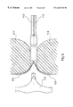
- FIG. 1 c shows the longitudinal cutting operation of the edges of the beads obtained from the preceding operation, seen at the extremity on the right section, the tooling being represented in cross-section.
- FIG. 1 d shows a side view of the shape of the tongues after cutting.
- FIG. 1 e shows a side view of the shaping operation of the fork link wings, the shaping dies being shown in cross-section and the mandrel released.
- FIG. 1 f shows a front view of the fork link after the shaping of the wings.
- FIG. 1 g shows a view from above of the fork link after punching the holes for a pin or a spider web and eventual finishing cuts.
- FIG. 2 shows an example of a bent tube portion with a fork link at each extremity.
- FIG. 3 shows an example of a semi-rigid rear axle for motor vehicle.
- FIG. 4 shows a detail of a sectional drawing of FIG. 3, in accordance with plan B.
- FIG. 5 shows another detail of the same sectional drawing of FIG. 3 in accordance with plan A.
- FIG. 6 shows the stage of shaping the semi-rigid rear axle for motor vehicle in FIG. 3; the shaping dies are shown in a sectional drawing and the mandrel released.
- FIGS. 1 a ) and 1 b ) show the operation for flattening the length of tube 1 .
- the length of tube 1 used for making the part in that example is a cylindrical tube portion with a constant section.
- the extremity of this tube portion undergoes, over a certain length, a first flattening operation.
- This flattening operation is done between two shaping dies, 2 and 2 ′, and results in the shaping of two longitudinal beads, 3 and 3 ′, of a given length, on opposite generating lines of the tube portion, the beads forming a metal fold, edge-to-edge, in the shape of a hair pin.
- FIGS. 1 c ) and 1 d ) show the cutting operation for beads 3 , 3 ′ at the flattened extremity.
- This extremity is held here between a stationary lower die 4 and an upper blank holder 5 .
- a vertically mobile upper die 6 allows to slide cutting tools 7 and 7 ′ laid out at 3 h and 9 h (in analogy to the position of the hour needle on a clock), along the aligned lateral edges 8 and 9 , and 8 ′ and 9 ′, respectively, of lower die 4 and blank holder 5 .
- Blank holder 5 leans against the upper extremity of the flattened tube by way of a spring 10 positioned between the blank holder 5 and the mobile upper die 6 .
- the scraps from cuttings 11 , 11 ′ are ejected toward the outside in the direction of arrows F, F′ in FIG. 1 c ).
- FIGS. 1 e ) and 1 f ) show the operation for shaping the fork link wings.
- the tube portion and its tongues 12 , 12 ′ are clamped between two shaping dies 14 - 14 ′ while punch 15 is inserted inside the split extremity and spreads tongues 12 - 12 ′ against the inside surface of dies 14 - 14 ′.
- Tongues 12 , 12 ′ then take on wing shapes 16 , 16 ′ of L length, and l width, parallel to each other and the tube portion 1 , at a distance H from each other.
- the wings obtained 16 - 16 ′ are flat except on the lateral edges, such as 17 , which are bent toward the outside of the part, this bending being the result of a counter-curvature such as 13 , itself a result of a folding-over such as 3 .
- Bending such as 17 allows to render wings 16 , 16 ′ rigid, and to keep them from sagging longitudinally, or to become twisted during the end use of the finished part.
- FIG. 1 g shows a fork link obtained on the extremity of tube portion 1 after finishing operations such as:
- Process in accordance with the invention allows to manufacture such fork links from a wide range of tube sizes (diameter, thickness), without any particular criticality along the length L of fork link wings, width l and spacing H.
- FIG. 2 shows an integral tubular part 30 obtained from structural steel tube 33 with an outside diameter of 36 mm and a thickness of 4 mm, bent twice at the center and outfitted with fork links 31 and 32 at each extremity; fork links obtained as described in FIG. 1 .
- the length of the fork link wings in the example under consideration, is 50 mm, their width 42 mm, and their spacing 56 mm. Holes 16 mm in diameter are made facing each other on each wing.
- symmetry plan XX of the fork link 31 is parallel to the symmetry plan YY of the other fork link 32 , at a distance of 76 mm from the other one, but these two plans could form together an angle in the case of other kinds of similar parts.
- FIG. 3 shows a semi-rigid rear axle 101 manufactured via the process in accordance with the invention, to be used in a motor vehicle.
- This axle is obtained from a weldable structural steel tube, whose central portion 102 undergoes shaping via appropriate mechanical or hydroforming means, so as to constitute an elastic torsion part of a known rigidity.
- the right section of the central portion 102 is shown in FIG. 5 .
- Each extremity of axle 101 consists of two wings 103 and 104 , without transverse curvature except for a bend such as 116 at the edges (FIG. 4) and attached to the central portion 102 , angle Y formed at the beginning by the two wings being on the order of 90°, and the extremity of the wings being perpendicular to axis XX of the initial tube.
- the extremities of wings such as 103 or 104 may be outfitted on wing 104 with elastic support bearings 105 which are articutated with the vehicle body, and on wing 103 with stub axles and helical spring extremity supports 107 .
- Wings 103 and 104 on a same extremity are rendered rigid and the angle between them closed by a housing 108 , made of U-shaped sheet metal cut to follow the contour of the wings, each branch 110 - 110 ′ of the U-shaped housing being welded onto 109 - 109 ′ on the folded edge, such as 116 , of the corresponding wing as indicated in FIG. 4 .
- Part 101 is obtained by having the extremities of a steel tube portion undergo a flattening operation and then a cutting of the outside projections of the two beads obtained in accordance with FIGS. 1 a ) to 1 d ).
- Wings 103 and 104 are then shaped as shown in FIG. 6 by deformation of tongues 112 and 112 ′ obtained after cutting.
- the body of the tube is crammed inside a shaping die consisting of two parts, 114 and 114 ′.
- Punch 115 comes to separate the tongues 112 - 112 ′ and push them against the lateral surface of the two die parts 114 - 114 ′ until forming a Y; each wing thus shaped is straightened transversally so as to remove any significant curvature in this direction, except for a small fold 116 at the lateral edges.
- Such a wing profile allows to center them longitudinally without any risk of tearing the most elongated areas.
- Housing 108 and parts 105 , 106 and 107 are then attached via welding.
Landscapes
- Engineering & Computer Science (AREA)
- Mechanical Engineering (AREA)
- Chemical & Material Sciences (AREA)
- Combustion & Propulsion (AREA)
- Transportation (AREA)
- Shaping Metal By Deep-Drawing, Or The Like (AREA)
- Wire Processing (AREA)
- Body Structure For Vehicles (AREA)
- Fluid-Damping Devices (AREA)
Applications Claiming Priority (3)
| Application Number | Priority Date | Filing Date | Title |
|---|---|---|---|
| FR97/05177 | 1997-04-18 | ||
| FR9705177A FR2762243B1 (fr) | 1997-04-18 | 1997-04-18 | Procede de fabrication de pieces en forme d'ailes et pieces resultant du procede |
| PCT/FR1998/000769 WO1998047644A1 (fr) | 1997-04-18 | 1998-04-16 | Procede de fabrication de pieces en forme d'ailes et pieces resultant du procede |
Publications (1)
| Publication Number | Publication Date |
|---|---|
| US6263720B1 true US6263720B1 (en) | 2001-07-24 |
Family
ID=9506341
Family Applications (1)
| Application Number | Title | Priority Date | Filing Date |
|---|---|---|---|
| US09/403,002 Expired - Fee Related US6263720B1 (en) | 1997-04-18 | 1998-04-16 | Method for making wing-shaped parts and resulting parts |
Country Status (7)
| Country | Link |
|---|---|
| US (1) | US6263720B1 (fr) |
| EP (1) | EP0975450B1 (fr) |
| AR (1) | AR012207A1 (fr) |
| BR (1) | BR9807931A (fr) |
| DE (1) | DE69817797T2 (fr) |
| FR (1) | FR2762243B1 (fr) |
| WO (1) | WO1998047644A1 (fr) |
Cited By (7)
| Publication number | Priority date | Publication date | Assignee | Title |
|---|---|---|---|---|
| US6739166B1 (en) * | 2002-12-17 | 2004-05-25 | General Motors Corporation | Method of forming tubular member with flange |
| DE10351138A1 (de) * | 2003-11-03 | 2005-06-16 | Daimlerchrysler Ag | Verfahren zur Herstellung eines länglichen hohlen Bauteils mit einem Anlagebauteil |
| US20060059974A1 (en) * | 2004-09-21 | 2006-03-23 | Hwashin Co., Ltd. | Apparatus for forming beam member used for torsion beam for rear wheel suspension of automobile |
| EP2028029A3 (fr) * | 2007-08-21 | 2009-12-02 | Benteler Automobiltechnik GmbH | Bâton profilé pouvant être monté en tant que traverse d'un essieu orientable mixte d'un véhicule automobile |
| CN101862941A (zh) * | 2010-06-18 | 2010-10-20 | 山东桑乐太阳能有限公司 | 一种太阳能热水器内胆成桶生产方法 |
| US20160279693A1 (en) * | 2013-12-09 | 2016-09-29 | Sumitomo Heavy Industries, Ltd. | Molding apparatus |
| US10220662B2 (en) * | 2012-06-08 | 2019-03-05 | Nippon Steel & Sumitomo Metal Corporation | Coupling structure, coupling member having coupling structure, and method for manufacturing coupling member having coupling structure |
Families Citing this family (3)
| Publication number | Priority date | Publication date | Assignee | Title |
|---|---|---|---|---|
| WO2001015828A1 (fr) * | 1999-08-27 | 2001-03-08 | Dorbyl Limited | Corps tubulaire pourvu d'une partie de fixation et procede permettant de produire une telle partie de fixation |
| FR2999115B1 (fr) * | 2012-12-11 | 2015-07-24 | Renault Sa | Essieu hybride de vehicule automobile |
| CN112276499A (zh) * | 2020-10-19 | 2021-01-29 | 抚州申铃汽车配件有限责任公司 | 一种汽车后桥半轴退火搓齿加工工艺 |
Citations (13)
| Publication number | Priority date | Publication date | Assignee | Title |
|---|---|---|---|---|
| US2133092A (en) * | 1936-10-07 | 1938-10-11 | Clark Equipment Co | Method of forming an axle housing |
| US2205893A (en) * | 1937-09-03 | 1940-06-25 | Gen Electric | Method of corrugating a heatradiating tube |
| US3181336A (en) | 1961-11-15 | 1965-05-04 | Schofield Hubert Percival | Method of producing the pointed end of a hypodermic needle |
| DE1813978A1 (de) | 1968-12-11 | 1970-07-02 | Manco Mfg Co | Formstempel fuer eine Rohrverformungseinrichtung |
| US4088001A (en) | 1976-09-13 | 1978-05-09 | Hosei Buleki Kogyo Kabushiki Kaisha | Method of manufacturing a strut member made of a tube material for use with drum brakes |
| US4095450A (en) * | 1977-03-21 | 1978-06-20 | Lear Siegler, Inc. | Axle making method and apparatus |
| US4192396A (en) | 1977-03-21 | 1980-03-11 | Lear Siegler, Inc. | Vehicle axle including endways opening axle end |
| DE3335912A1 (de) | 1983-10-03 | 1985-04-18 | Reiche & Co, 4937 Lage | Verfahren zum herstellen eines rohranschlusses sowie ein danach hergestelltes rohr |
| US4621421A (en) * | 1984-09-17 | 1986-11-11 | Thomas & Betts Corporation | Method of making an electrical terminal |
| GB2197051A (en) | 1986-11-06 | 1988-05-11 | Melchor Duamal Castellon | Fork for cardan joints |
| US5070717A (en) * | 1991-01-22 | 1991-12-10 | General Motors Corporation | Method of forming a tubular member with flange |
| FR2734207A1 (fr) | 1995-05-19 | 1996-11-22 | Vallourec Vitry | Essieu semi-rigide pour vehicule |
| FR2737177A1 (fr) | 1995-07-28 | 1997-01-31 | Vallourec Vitry | Berceau tubulaire pour vehicule automobile |
-
1997
- 1997-04-18 FR FR9705177A patent/FR2762243B1/fr not_active Expired - Lifetime
-
1998
- 1998-03-30 AR ARP980101444A patent/AR012207A1/es unknown
- 1998-04-16 EP EP98921548A patent/EP0975450B1/fr not_active Expired - Lifetime
- 1998-04-16 DE DE69817797T patent/DE69817797T2/de not_active Expired - Fee Related
- 1998-04-16 US US09/403,002 patent/US6263720B1/en not_active Expired - Fee Related
- 1998-04-16 WO PCT/FR1998/000769 patent/WO1998047644A1/fr not_active Ceased
- 1998-04-16 BR BR9807931-0A patent/BR9807931A/pt not_active IP Right Cessation
Patent Citations (13)
| Publication number | Priority date | Publication date | Assignee | Title |
|---|---|---|---|---|
| US2133092A (en) * | 1936-10-07 | 1938-10-11 | Clark Equipment Co | Method of forming an axle housing |
| US2205893A (en) * | 1937-09-03 | 1940-06-25 | Gen Electric | Method of corrugating a heatradiating tube |
| US3181336A (en) | 1961-11-15 | 1965-05-04 | Schofield Hubert Percival | Method of producing the pointed end of a hypodermic needle |
| DE1813978A1 (de) | 1968-12-11 | 1970-07-02 | Manco Mfg Co | Formstempel fuer eine Rohrverformungseinrichtung |
| US4088001A (en) | 1976-09-13 | 1978-05-09 | Hosei Buleki Kogyo Kabushiki Kaisha | Method of manufacturing a strut member made of a tube material for use with drum brakes |
| US4095450A (en) * | 1977-03-21 | 1978-06-20 | Lear Siegler, Inc. | Axle making method and apparatus |
| US4192396A (en) | 1977-03-21 | 1980-03-11 | Lear Siegler, Inc. | Vehicle axle including endways opening axle end |
| DE3335912A1 (de) | 1983-10-03 | 1985-04-18 | Reiche & Co, 4937 Lage | Verfahren zum herstellen eines rohranschlusses sowie ein danach hergestelltes rohr |
| US4621421A (en) * | 1984-09-17 | 1986-11-11 | Thomas & Betts Corporation | Method of making an electrical terminal |
| GB2197051A (en) | 1986-11-06 | 1988-05-11 | Melchor Duamal Castellon | Fork for cardan joints |
| US5070717A (en) * | 1991-01-22 | 1991-12-10 | General Motors Corporation | Method of forming a tubular member with flange |
| FR2734207A1 (fr) | 1995-05-19 | 1996-11-22 | Vallourec Vitry | Essieu semi-rigide pour vehicule |
| FR2737177A1 (fr) | 1995-07-28 | 1997-01-31 | Vallourec Vitry | Berceau tubulaire pour vehicule automobile |
Cited By (14)
| Publication number | Priority date | Publication date | Assignee | Title |
|---|---|---|---|---|
| US6739166B1 (en) * | 2002-12-17 | 2004-05-25 | General Motors Corporation | Method of forming tubular member with flange |
| DE10351138A1 (de) * | 2003-11-03 | 2005-06-16 | Daimlerchrysler Ag | Verfahren zur Herstellung eines länglichen hohlen Bauteils mit einem Anlagebauteil |
| DE10351138B4 (de) * | 2003-11-03 | 2005-10-06 | Daimlerchrysler Ag | Verfahren zur Herstellung eines länglichen hohlen Bauteils mit einem Anlagebauteil |
| US20070131341A1 (en) * | 2003-11-03 | 2007-06-14 | Daimlerchrysler Ag | Method for producing an elongate hollow member comprising a mounting component |
| US20060059974A1 (en) * | 2004-09-21 | 2006-03-23 | Hwashin Co., Ltd. | Apparatus for forming beam member used for torsion beam for rear wheel suspension of automobile |
| US7257982B2 (en) * | 2004-09-21 | 2007-08-21 | Hwashin Co., Ltd. | Apparatus for forming a beam member used as a torsion beam for the rear wheel suspension of an automobile |
| EP2028029A3 (fr) * | 2007-08-21 | 2009-12-02 | Benteler Automobiltechnik GmbH | Bâton profilé pouvant être monté en tant que traverse d'un essieu orientable mixte d'un véhicule automobile |
| CN101862941A (zh) * | 2010-06-18 | 2010-10-20 | 山东桑乐太阳能有限公司 | 一种太阳能热水器内胆成桶生产方法 |
| CN101862941B (zh) * | 2010-06-18 | 2011-09-14 | 山东桑乐太阳能有限公司 | 一种太阳能热水器内胆成桶生产方法 |
| US10220662B2 (en) * | 2012-06-08 | 2019-03-05 | Nippon Steel & Sumitomo Metal Corporation | Coupling structure, coupling member having coupling structure, and method for manufacturing coupling member having coupling structure |
| US10377200B2 (en) | 2012-06-08 | 2019-08-13 | Nippon Steel Corporation | Coupling structure, coupling member having coupling structure, and method for manufacturing coupling member having coupling structure |
| US20160279693A1 (en) * | 2013-12-09 | 2016-09-29 | Sumitomo Heavy Industries, Ltd. | Molding apparatus |
| US10173254B2 (en) * | 2013-12-09 | 2019-01-08 | Sumitomo Heavy Industries, Ltd. | Molding apparatus |
| CN110560545A (zh) * | 2013-12-09 | 2019-12-13 | 住友重机械工业株式会社 | 成型装置 |
Also Published As
| Publication number | Publication date |
|---|---|
| AR012207A1 (es) | 2000-09-27 |
| EP0975450B1 (fr) | 2003-09-03 |
| DE69817797D1 (de) | 2003-10-09 |
| WO1998047644A1 (fr) | 1998-10-29 |
| BR9807931A (pt) | 2000-02-22 |
| FR2762243B1 (fr) | 1999-06-11 |
| DE69817797T2 (de) | 2004-07-15 |
| FR2762243A1 (fr) | 1998-10-23 |
| EP0975450A1 (fr) | 2000-02-02 |
Similar Documents
| Publication | Publication Date | Title |
|---|---|---|
| US6302478B1 (en) | Hydroformed space frame joints therefor | |
| US20020162224A1 (en) | Hydroformed vehicle frame assembly and method | |
| EP1301291B1 (fr) | Procede de fabrication d'un renfort de porte tubulaire monobloc | |
| US6263720B1 (en) | Method for making wing-shaped parts and resulting parts | |
| US5884722A (en) | Engine cradle for vehicle body and frame assembly and method of manufacturing same | |
| US6842957B2 (en) | Process for producing a tubular component | |
| US4974436A (en) | Cutting tool to facilitate bending of hollow tubing | |
| CA2406456A1 (fr) | Cadre modulaire de chassis en treillis | |
| JPH07246894A (ja) | ロール成形された自動車用バンパーと、その製造方法 | |
| US6138358A (en) | Method of manufacturing a vehicle body and frame assembly | |
| KR101230592B1 (ko) | 일체형 트레일링 암 및 그 제조방법 | |
| GB797137A (en) | Chassis frame with tubular side frame members for automobiles | |
| DE102009031981A1 (de) | Verfahren zur Herstellung eines Kraftfahrzeugbauteils in Form eines Torsionsprofils | |
| US6978545B2 (en) | Method of manufacturing a vehicle body and frame assembly | |
| US6186696B1 (en) | Method for the crosswise shrinking of a cylindrical part in a tubular part, tool kit for its implementation, and assembly of two corresponding parts | |
| US20060096099A1 (en) | Automotive crush tip and method of manufacturing | |
| CA2543265A1 (fr) | Production de pieces produites par deformation par haute pression interne et pourvues d'une bride | |
| JPS6148442B2 (fr) | ||
| US6519855B1 (en) | Method of manufacturing a vehicle body and frame assembly | |
| US11124032B2 (en) | Method for producing motor vehicle controls and the resulting motor vehicle control | |
| US1991988A (en) | Method for forming axle housings | |
| EP1364817B1 (fr) | Bras de suspension monopièce | |
| US2625055A (en) | Axle housing | |
| JP2001287629A (ja) | 自動車用ブレーキペダル本体の製造方法 | |
| EP1814771A2 (fr) | Point d'ecrasement pour vehicules automobiles et procede de production correspondant |
Legal Events
| Date | Code | Title | Description |
|---|---|---|---|
| AS | Assignment |
Owner name: VALLOUREC COMPOSANTS AUTOMOBILES VITRY, FRANCE Free format text: ASSIGNMENT OF ASSIGNORS INTEREST;ASSIGNOR:VALIN, DANIEL;REEL/FRAME:010621/0409 Effective date: 19991008 |
|
| FPAY | Fee payment |
Year of fee payment: 4 |
|
| FEPP | Fee payment procedure |
Free format text: PAYOR NUMBER ASSIGNED (ORIGINAL EVENT CODE: ASPN); ENTITY STATUS OF PATENT OWNER: LARGE ENTITY |
|
| FPAY | Fee payment |
Year of fee payment: 8 |
|
| REMI | Maintenance fee reminder mailed | ||
| LAPS | Lapse for failure to pay maintenance fees | ||
| STCH | Information on status: patent discontinuation |
Free format text: PATENT EXPIRED DUE TO NONPAYMENT OF MAINTENANCE FEES UNDER 37 CFR 1.362 |
|
| FP | Lapsed due to failure to pay maintenance fee |
Effective date: 20130724 |