US6263541B1 - Winding cone of an overhead door counterbalancing mechanism and torsion spring winding method therefor - Google Patents
Winding cone of an overhead door counterbalancing mechanism and torsion spring winding method therefor Download PDFInfo
- Publication number
- US6263541B1 US6263541B1 US09/234,616 US23461699A US6263541B1 US 6263541 B1 US6263541 B1 US 6263541B1 US 23461699 A US23461699 A US 23461699A US 6263541 B1 US6263541 B1 US 6263541B1
- Authority
- US
- United States
- Prior art keywords
- coupling member
- torsion spring
- component
- torsion
- fastener
- Prior art date
- Legal status (The legal status is an assumption and is not a legal conclusion. Google has not performed a legal analysis and makes no representation as to the accuracy of the status listed.)
- Expired - Fee Related
Links
Images


Classifications
-
- E—FIXED CONSTRUCTIONS
- E05—LOCKS; KEYS; WINDOW OR DOOR FITTINGS; SAFES
- E05D—HINGES OR SUSPENSION DEVICES FOR DOORS, WINDOWS OR WINGS
- E05D13/00—Accessories for sliding or lifting wings, e.g. pulleys, safety catches
- E05D13/10—Counterbalance devices
- E05D13/12—Counterbalance devices with springs
- E05D13/1253—Counterbalance devices with springs with canted-coil torsion springs
- E05D13/1269—Spring safety devices
-
- E—FIXED CONSTRUCTIONS
- E05—LOCKS; KEYS; WINDOW OR DOOR FITTINGS; SAFES
- E05D—HINGES OR SUSPENSION DEVICES FOR DOORS, WINDOWS OR WINGS
- E05D13/00—Accessories for sliding or lifting wings, e.g. pulleys, safety catches
- E05D13/10—Counterbalance devices
- E05D13/12—Counterbalance devices with springs
- E05D13/1253—Counterbalance devices with springs with canted-coil torsion springs
- E05D13/1261—Counterbalance devices with springs with canted-coil torsion springs specially adapted for overhead wings
-
- E—FIXED CONSTRUCTIONS
- E05—LOCKS; KEYS; WINDOW OR DOOR FITTINGS; SAFES
- E05D—HINGES OR SUSPENSION DEVICES FOR DOORS, WINDOWS OR WINGS
- E05D13/00—Accessories for sliding or lifting wings, e.g. pulleys, safety catches
-
- E—FIXED CONSTRUCTIONS
- E05—LOCKS; KEYS; WINDOW OR DOOR FITTINGS; SAFES
- E05Y—INDEXING SCHEME RELATING TO HINGES OR OTHER SUSPENSION DEVICES FOR DOORS, WINDOWS OR WINGS AND DEVICES FOR MOVING WINGS INTO OPEN OR CLOSED POSITION, CHECKS FOR WINGS AND WING FITTINGS NOT OTHERWISE PROVIDED FOR, CONCERNED WITH THE FUNCTIONING OF THE WING
- E05Y2201/00—Constructional elements; Accessories therefore
- E05Y2201/40—Motors; Magnets; Springs; Weights; Accessories therefore
- E05Y2201/47—Springs; Spring tensioners
- E05Y2201/492—Spring tensioners, tension sensors
-
- E—FIXED CONSTRUCTIONS
- E05—LOCKS; KEYS; WINDOW OR DOOR FITTINGS; SAFES
- E05Y—INDEXING SCHEME RELATING TO HINGES OR OTHER SUSPENSION DEVICES FOR DOORS, WINDOWS OR WINGS AND DEVICES FOR MOVING WINGS INTO OPEN OR CLOSED POSITION, CHECKS FOR WINGS AND WING FITTINGS NOT OTHERWISE PROVIDED FOR, CONCERNED WITH THE FUNCTIONING OF THE WING
- E05Y2800/00—Details, accessories and auxiliary operations not otherwise provided for
- E05Y2800/26—Form, shape
-
- E—FIXED CONSTRUCTIONS
- E05—LOCKS; KEYS; WINDOW OR DOOR FITTINGS; SAFES
- E05Y—INDEXING SCHEME RELATING TO HINGES OR OTHER SUSPENSION DEVICES FOR DOORS, WINDOWS OR WINGS AND DEVICES FOR MOVING WINGS INTO OPEN OR CLOSED POSITION, CHECKS FOR WINGS AND WING FITTINGS NOT OTHERWISE PROVIDED FOR, CONCERNED WITH THE FUNCTIONING OF THE WING
- E05Y2900/00—Application of doors, windows, wings or fittings thereof
- E05Y2900/10—Application of doors, windows, wings or fittings thereof for buildings or parts thereof
- E05Y2900/106—Application of doors, windows, wings or fittings thereof for buildings or parts thereof for garages
Definitions
- the present invention relates to a winding cone for a torsion spring and, in particular, to a winding cone used in a torsion spring assembly of an overhead door counterbalancing mechanism.
- a conventional winding cone includes both a frusto-conical surface for receiving and retaining an end of a torsion spring and a base having an opening therein for receiving a set screw whereby the end of the spring is fixed to a torsion rod extending axially through the winding cone.
- Balk U.S. Pat. No. 5,671,500 is illustrative of a conventional torsion spring assembly used in a counterbalancing mechanism for an overhead door.
- the torsion spring 3 is axially disposed about torsion rod 20 .
- One end of the spring is retained by cone 16 that is mounted to the rod 20 by adjustable mounting 18
- the other end of the spring is retained by cone and bracket 12 which are rotationally fixed relative to rod 20 .
- Rotation of rod 20 causes rotation of mounting 18 , cone 16 , and torsion spring 3 leading to a change in the tension of the torsion spring 3 .
- the tension range is adjusted by: first releasing a set screw which fixes mounting 18 to rod 20 ; next rotating mounting 18 , cone 16 , and spring 3 relative to the rod 20 in the desired direction; and then re-engaging the set screw with the rod 20 through the mounting 18 .
- No failsafe is provided to insure that the tension in torsion spring 3 will be maintained when the set screw is released from torsion rod 20 .
- Martin U.S. Pat. No. 4,817,927 discloses in FIG. 4 a winding cone 60 and, in FIG. 3, an anchor cone 10 .
- a tool (not shown) is inserted into apertures 68 or 69 for selectively adjusting the tension in the torsion spring 50 and set screws are provided through aperture 64 in base 62 for mounting the winding cone to the torsion rod 34 .
- Martin provides markings on the winding cones to indicate which direction each cone should be rotated to wind the torsion spring 50 .
- 3,779,537 discloses a winding cone and winding base that includes both left-hand and right-hand threads for receiving either a left-hand or right-hand wound spring. Similar to Martin, the winding cone is secured to the torsion rod by set screws. The winding cones of both of these references fail to provide a failsafe for insuring that the torque of the torsion spring is adequately braced against when the winding cone is released from the torsion rod for winding of the torsion spring.
- Way U.S. Pat. No. 5,605,079 actually relates to a device for rotating the winding cone and winding the torsion spring for increasing winding tension.
- Way discloses a housing that is mountable to a winding cone to which ratchet arms are attachable for increasing the tension in the torsion spring.
- a ratchet arm In using the device, a ratchet arm must be braced to counteract the force of the torsion spring that is released when the set screw is removed.
- no failsafe is provided whereby the spring force must first be overcome before disengagement of the set screw.
- the opening 66 by which the set screw is accessible is continuously aligned with the set screw 34 and the housing 36 in which the opening is formed is fixed to the winding cone.
- the set screw is continuously accessible in the device of Way.
- the prior art also includes devices for adjusting the operating tension range in a torsion spring assembly which does not involve the rotation of the winding cone relative to the torsion rod and, thus, does not include the dismounting of the winding cone from the torsion rod to which the failsafe of the present invention relates.
- Such devices are disclosed, for example, by Davis U.S. Pat. No. 4,882,806; Carper et al. U.S. Pat. Nos. 5,636,678 and 5,632,063; and Husselton U.S. Pat. No. 5,239,777. None of these mechanisms relate to the winding of the torsion spring by rotation of the winding cone relative to the torsion shaft, nor do they provide a safeguard against an inadequate force bracing against the release of the torsion spring tension.
- Rapp U.S. Pat. No. 4,817,242 a spring hinge for a toilet seat is disclosed wherein the tension in the torsion spring is adjustable.
- Rapp discloses, with relevance to the present invention, a torsion spring 2 axially disposed about a rod 1 within a hinge. A first end of the torsion spring 2 is secured to end cap 9 and a second end of the torsion spring is secured to a first coupling member 6 that is mounted to the rod 1 and that has teeth which interlock with a second coupling member 5 .
- End cap 9 is mounted to the toilet and second coupling member 5 is mounted to the seat.
- the first coupling member 6 , and the second coupling member 5 when interlocked therewith, are rotational with the rod 1 relative to end cap 9 , which rotation increases and decreases the tension in torsion spring 2 within a certain range.
- This range of tension is adjusted by: first axially moving the first coupling member 6 away from the second coupling member 5 into an unlocked position by axially displacing rod 1 against the spring force via knob 8 thereby compressing the spring; then rotating the first coupling member 6 and the spring 2 attached thereto relative to the second coupling member 5 by rotating rod 1 via knob 8 ; and then moving the first coupling member 6 back into interlocking relation with the second coupling member 5 by releasing the knob 8 .
- contoured engagement surfaces 26 , 27 Due to the contoured engagement surfaces 26 , 27 , rotation of the wrench about the axis of the torsion spring 23 in a first direction will cause the cone 24 and plug 20 to rotate relative to one another in segmented increments. However, the contoured engagement surfaces 26 , 27 prevent the rotation of the cone 24 and plug 20 in the segmented steps in the opposite direction unless the cone 24 and plug 20 are separated by an axial force applied directly to the cone 24 via the wrench 29 .
- Hwang U.S. Pat. No. 5,048,155 discloses a spring hinge in which the torsion spring biasing the hinge has an adjustable tension range.
- torsion spring 30 is retained between end cap 50 , secured to a first hinge by set screw 90 , and end cap 40 secured to a second hinge by set screw 70 .
- a number of openings are formed in the second hinge member 10 and, in particular, in knuckle 12 in which the end cap 40 is disposed, through which set screw 70 can engage and retain end cap 40 .
- a pin 83 and openings for the pin in knuckle 12 are also provided whereby the end cap 40 can be immobilized when set screw 70 is removed.
- One of the winding cone components receives and retains an end of a torsion spring and the other component anchors the first component to a torsion rod.
- the present invention broadly encompasses a winding cone comprising a first mounting component defining an area for receiving therein a fastener for mounting of the first component to a torsion rod for rotation therewith; and a second winding component including a frusto-conical surface for receiving an end of a torsion spring.
- the second component is disposed adjacent the first component for limited rotational movement about an axis of and relative to the first component between first and second rotational positions.
- the second component includes a covering portion disposed relative to the first component such that the covering portion inhibits access to the area of the fastener when the second component is in the first rotational position.
- the covering portion permits access to the area of the fastener when the second component is in the second rotational position.
- the first component includes a blocking portion which engages the second component and prevents rotation of the second component relative to the first component in a first rotational direction when the second component is in the first rotational position.
- a counterbalancing mechanism for an overhead door of the present invention includes a first torsion spring assembly having a torsion rod extending along a longitudinal axis of and within a torsion spring; an anchor member retaining a first end of the torsion spring with the torsion rod being rotatable about the axis relative to the anchor member; and a winding cone of the present invention retaining a second end of the torsion spring.
- a method of the present invention includes winding a torsion spring retained at one end by an anchor and at another end by a winding component engaged with a mounting component to form a winding cone.
- the steps of the method include gaining access to a fastener securing the mounting component to a torsion rod by applying torque against the torque of the torsion spring to the winding component which covers the fastener; releasing the fastener to unfasten the mounting component from the torsion rod while applying the torque; winding the torsion spring by applying a greater torque to the winding component against the torque of the torsion spring; fastening the fastener to remount the mounting component to the torsion rod while applying the greater torque; and covering the fastener with the winding component by discontinuing the application of torque to the winding component.
- FIG. 1 is a perspective, exploded view of two coupling members of a winding cone of the present invention
- FIG. 2 is a perspective view of the winding cone of FIG. 1 in a first rotational position
- FIG. 3 is a perspective view of the winding cone of FIG. 1 in a second rotational position
- FIG. 4 is a perspective, exploded view of two coupling members of another winding cone of the present invention.
- FIG. 5 is a reverse angle perspective, exploded view of the two coupling members of FIG. 4;
- FIG. 6 is a perspective view of the winding cone of FIG. 4 in a first rotational position
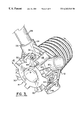
- FIG. 7 is a perspective view of the winding cone of FIG. 4 in a second rotational position
- FIG. 8 is an plan view along an axis of the winding cone of FIG. 6.
- FIG. 9 is a perspective view of the counterbalancing mechanism of the present invention.
- FIGS. 1-3 Two preferred embodiments of the winding cone of the present invention are shown in the drawings.
- the winding cone of FIGS. 1-3 is a simpler embodiment and is designed for use with a right-hand torsion spring
- the winding cone of FIGS. 4-8 can be used with either a right hand torsion spring or a left hand torsion spring.
- the components forming the winding cone of FIGS. 4-9 are versatile and molds for manufacturing the components do not depend upon the type of torsion spring with which the components will be utilized.
- the winding cone 10 is formed by the combination of two components, namely, a first winding cone coupling member 12 and a second winding cone coupling member 14 .
- first and second coupling members 12 , 14 are shown in exploded view along axis 16 .
- the first coupling member 12 comprises a winding component and includes a frusto conical surface 18 having spiral grooves 20 for receiving and retaining the coils of an end of a conventional torsion spring 21 (shown, for example, in FIG. 9 ).
- a polygonal ring 22 is disposed at one end of the frusto conical surface 20 and is coaxial therewith.
- the ring 22 includes four radial extensions 24 symmetrically disposed about axis 16 , with at least one radial extension 24 (but preferably all) defining an opening 26 for receiving therein a winding bar 28 (shown in FIG. 3) for winding of the torsion spring 21 when secured on the frusto conical surface 18 .
- Four guide members 30 extend generally axially from the ring 22 and, in conjunction with the radial extensions 24 , define a discontinuous surface 32 of the first coupling member 12 disposed circumferentially about axis 16 for snuggly receiving a cylindrical body 34 of the second coupling member 14 therein, as shown in FIGS. 2-3.
- the first coupling member 12 is nevertheless configured for rotational movement around the second coupling member 14 about axis 16 .
- the second coupling member 14 includes blocking portions 36 which engage the guide members 30 of the first coupling member 12 when the first coupling member 12 is rotated by an attached torsion spring 21 in a first rotational direction ⁇ into a first rotational position I shown in FIG. 2 .
- Each blocking portion 36 also includes a slanted surface 38 which tends to urge the first coupling member 12 into abutment with the second coupling member 14 when the first coupling member 12 is urged in the first rotational direction ⁇ by the attached torsion spring 21 .
- Each guide member 30 also preferably includes a corresponding slanted surface 40 for urging the first coupling member 12 into abutment with the second coupling member 14 as a result of the torque of the torsion spring 21 when attached.
- the second coupling member 14 comprises a mounting component and is adapted to be releasably secured to a torsion rod 42 (shown in FIG. 9) when extending along axis 16 of FIG. 1 .
- the second coupling member 14 includes fastener receiving areas 44 preferably defined within said blocking portions 36 through which a fastener such a set screw 46 is disposed for mounting of the second coupling member 14 to the torsion rod 42 .
- the first coupling member 12 When the first coupling member 12 is disposed in the first rotational position I as shown in FIG. 2, the first coupling member 12 includes covering portion 48 each of which extends over a blocking portion 36 of the second coupling member 14 and blocks access to a fastener receiving area 44 and any set screw 46 disposed therein. Release of the set screw 46 is thereby prevented until the first coupling member 12 is rotated in a second rotational direction ⁇ opposite the first rotational direction ⁇ to a second rotational position II as shown in FIG. 3 . Movement of the first coupling member 12 is against the torque of the attached torsion spring 21 which urges the first coupling member 12 towards the first rotational position I.
- each radial extension 24 defines an opening 26 for receiving therein a winding bar 28 as mentioned above and as shown in FIG. 3 .
- the winding cone 50 of FIGS. 4-8 also includes a first coupling member 12 and a second coupling member 14 .
- fastener receiving areas 44 preferably are formed in just two blocking portions 60 .
- the winding cone 50 may be used with either a right-hand torsion spring or a left-hand torsion spring
- four covering portions 48 of the first coupling member 12 are provided circumferentially disposed about axis 16 in an asymmetrical configuration whereby a pair 52 of covering portions 48 cover the pair 54 of fastener receiving areas 44 when the first coupling member 12 is disposed in the first rotational position I, and a pair 58 of covering portions 48 cover the pair 60 of blocking portions 36 lacking the fastener receiving areas 44 when the first coupling member 12 is disposed in the second rotational position II.
- a projecting tab portion 62 is also provided on the second coupling member 14 which radially extends therefrom for disposition within a limited rotational area 64 defined by the first coupling member 12 , whereby the second coupling member 14 will not fit within the first coupling member 12 unless the projecting tab portion 62 is properly aligned with the limited rotational area 64 .
- the blocking portions 36 themselves are symmetrically disposed circumferentially about axis 16 . Consequently, the winding cone 50 may be used with a right-hand torsion spring resulting in the disposition of the first coupling member 12 as shown in FIG. 8 .
- the second coupling member 14 need only be reversed whereby the torque of the left-hand torsion spring would thereby urge the pair of covering portions 52 into covering relation with the pair 56 of blocking portions 36 including the pair 54 of fastener receiving areas 44 .
- the projecting tab portion 62 thereby insures that the first coupling member 12 and the second coupling member 14 are oriented for proper covering of the pair 56 of blocking portions 36 having the pair 54 of fastener receiving areas 44 formed therein when the second coupling member 14 is reversed.
- fastener receiving areas 44 are provided in each blocking portion 36 (not shown), then the second coupling member 14 need not be reversed in order to use the winding cone 50 shown in FIG. 8 with a left-hand torsion spring. Instead, set screws 46 may be disposed through fastener receiving areas 44 in the pair 60 of blocking portions 36 instead of the pair 56 of blocking portions 36 . The winding cone 50 illustrated in FIG. 8 would then be disposed in the second rotational position II with the set screws 46 exposed.
- winding cone 50 of FIGS. 4-8 and winding cone 10 of FIGS. 1-3 includes the addition on each blocking portion 36 of the winding cone 50 of slanted engagement surfaces 66 which form a V-shaped projecting portion 68 . Further, a V-shaped projecting portion 68 is formed on each rotational side of each blocking portion 36 , and each guide member 30 and radial extension 24 of the first coupling member 12 together include slanted engagement surfaces 70 which define a V-shaped recess 72 on each rotational side thereof for receipt of one of the V-shaped projection portions 68 therein.
- the two coupling members 12 , 14 are not only urged into abutment by the torque of the torsion spring 21 when the first coupling member 12 is in the first rotational position I, but also urged into abutment when the torque of the torsion spring is manually overcome and the first coupling member 12 is rotated into the second rotational position II to thereby provide axial stability to the first coupling member 12 as the set screws 46 are released.
- a counterbalancing mechanism 74 for an overhead door 76 is shown in FIG. 9 .
- the counterbalancing mechanism 74 utilizes two torsion spring assemblies.
- Each torsion spring assembly 78 , 80 includes a winding cone 50 of the present invention and a torsion spring 21 oppositely wound to that of the torsion spring 21 of the other torsion spring assembly 80 , 78 .
- a winding bar 28 for winding of the torsion spring 21 is inserted into an opening 26 of a radial extension 24 of the first coupling member 12 .
- a torque T is then applied opposite the torque S of the torsion spring 21 whereby the first coupling member 12 is rotated out of the first rotational position I to the second rotational position II whereat access is gained to the set screws 46 disposed within the fastener receiving areas 44 initially obstructed by the covering portions 48 .
- the blocking portions 36 engage the guide members 30 and radial extensions 24 and provide axial stability to the first coupling member 12 when in the second rotational position II. It will also be noted that by applying a torque T sufficient to rotate the first coupling member 12 to the second rotational position II, the torsion spring 21 is incrementally wound.
- the set screws 46 for which access has been gained are unsecured whereby the second coupling member 14 is freed to rotate with respect to the torsion rod 42 . Furthermore, during rotation and winding of the torsion spring 21 preferably the first coupling member 12 remains in abutment with the second coupling member 14 for rotation of the winding cone.
- the winding bar 28 is then used to continue to wind the torsion spring 21 against the spring torque until the desired tension is obtained. If the torsion spring assembly needs to be disassembled or the tension thereof simply needs to be relieved or lessened, the winding cone is wound in the same manner but in the reverse direction, i.e., in the direction of the spring torque.
- a second winding bar 28 is preferably inserted into another of the openings 26 whereby alternate stepped use of the winding bars 28 permits continued rotation of the winding cone to a desired tension.
- the set screws 46 are again secured to the torsion rod 42 .
- the torque manually applied to the first coupling member 12 is then decreased as the first coupling member 12 is rotated back into the first rotational position I to again block access to the set screws 46 .
- the winding bar 28 then in use is removed once the blocking portions 36 are engaged by the first coupling member 12 in the first rotational position I.
- the set screws 46 need not be refastened.
- the winding cone of the present invention thus provides in a simple, and convenient manner a safety feature not enjoyed by conventional winding cones.
- the winding cone of the present invention prevents access to the fasteners until the torque of the torsion spring is overcome, whereby the danger of the torsion spring being greater than expected and suddenly unwinding when the set screws are released is avoided.
- the projection tab portion while insuring proper orientation of the coupling members as discussed above, itself also may serve as a blocking portion preventing the rotation of the first coupling member in the first rotational direction from the first rotational position.
Landscapes
- Engineering & Computer Science (AREA)
- Mechanical Engineering (AREA)
- Closing And Opening Devices For Wings, And Checks For Wings (AREA)
- Springs (AREA)
Abstract
Description
Claims (30)
Priority Applications (1)
| Application Number | Priority Date | Filing Date | Title |
|---|---|---|---|
| US09/234,616 US6263541B1 (en) | 1999-01-21 | 1999-01-21 | Winding cone of an overhead door counterbalancing mechanism and torsion spring winding method therefor |
Applications Claiming Priority (1)
| Application Number | Priority Date | Filing Date | Title |
|---|---|---|---|
| US09/234,616 US6263541B1 (en) | 1999-01-21 | 1999-01-21 | Winding cone of an overhead door counterbalancing mechanism and torsion spring winding method therefor |
Publications (1)
| Publication Number | Publication Date |
|---|---|
| US6263541B1 true US6263541B1 (en) | 2001-07-24 |
Family
ID=22882100
Family Applications (1)
| Application Number | Title | Priority Date | Filing Date |
|---|---|---|---|
| US09/234,616 Expired - Fee Related US6263541B1 (en) | 1999-01-21 | 1999-01-21 | Winding cone of an overhead door counterbalancing mechanism and torsion spring winding method therefor |
Country Status (1)
| Country | Link |
|---|---|
| US (1) | US6263541B1 (en) |
Cited By (13)
| Publication number | Priority date | Publication date | Assignee | Title |
|---|---|---|---|---|
| US6485006B1 (en) * | 1999-07-16 | 2002-11-26 | Canimex Inc. | Plug with safety means for use with counterbalancing systems of garage doors and the like |
| US6502281B2 (en) * | 2000-07-14 | 2003-01-07 | Canimex Inc. | Plug for operatively connecting torsion springs to overhead shafts of counterbalancing systems used for garage doors and the like |
| US6694673B2 (en) * | 2000-04-25 | 2004-02-24 | Canimex Inc. | Eccentrically mountable plug for counterbalancing systems of garage doors and the like |
| US6735905B1 (en) * | 2001-03-14 | 2004-05-18 | Chi Overhead Doors, Inc. | Ratcheting winding cone |
| US20050011620A1 (en) * | 2003-07-15 | 2005-01-20 | Crouch Josh S. | Method and apparatus for suspending a door |
| US20070084012A1 (en) * | 2005-04-13 | 2007-04-19 | Canimex Inc. | Noise-reducing plug, and door assembly including the same |
| EP2172306A1 (en) * | 1991-03-14 | 2010-04-07 | Crawford Group AB | Adjustment of spring tension |
| US20100101047A1 (en) * | 2008-10-02 | 2010-04-29 | Caldwell Manufacturing Company | Apparatus and Method for Canceling Opposing Torsional Forces in a Compound Balance |
| WO2017156456A1 (en) * | 2016-03-10 | 2017-09-14 | David Feng | Coupler |
| US10357872B1 (en) | 2017-08-01 | 2019-07-23 | Jeffrey Gabelsberg | Winding cone adaptor |
| US20200087963A1 (en) * | 2018-09-18 | 2020-03-19 | Lawrence Schumacher | Double Headed Spring Winding Cone |
| US20220025699A1 (en) * | 2020-07-27 | 2022-01-27 | Eastern Metal Supply Inc. | Torsion spring adjuster |
| US11279011B1 (en) * | 2020-10-15 | 2022-03-22 | The Government of the United States of America, as represented by the Secretary of Homeland Security | Negator spring tool for paratroop door |
Citations (18)
| Publication number | Priority date | Publication date | Assignee | Title |
|---|---|---|---|---|
| US3615065A (en) * | 1968-12-09 | 1971-10-26 | Adelma O Elliott | Torsion counterbalance with cable pretensioning device |
| US3685567A (en) * | 1969-09-18 | 1972-08-22 | Paul E Pemberton | Sectional fire door assembly |
| US3779537A (en) * | 1973-02-20 | 1973-12-18 | Napoleon Spring Works Inc | Cone apparatus |
| US3979977A (en) * | 1975-06-16 | 1976-09-14 | Edward Dorma | Power tool |
| US4073038A (en) | 1976-10-07 | 1978-02-14 | Henry Soss And Company | Pintle with adjustable spring tension motor |
| US4817242A (en) | 1987-04-13 | 1989-04-04 | Rapp Sandu Z | Toilet seat spring hinge having an adjustable spring force |
| US4817927A (en) | 1986-08-21 | 1989-04-04 | Martin Door Manufacturing | Coil torsion spring mounting cones with groove break and method of mounting |
| US4882806A (en) | 1988-07-11 | 1989-11-28 | Davis Thomas J | Counterbalancing torsion spring mechanism for devices which move up and down and method of setting the torsion springs thereof |
| US4930182A (en) * | 1989-04-14 | 1990-06-05 | Apco Power-Unit Corporation | Apparatus for counterbalancing an overhead door |
| US4981165A (en) * | 1989-04-11 | 1991-01-01 | Millco Products, Inc. | Spring adjustment device for overhead doors |
| US5048155A (en) | 1989-09-11 | 1991-09-17 | Hyundae Precision Co., Ltd. | Set screw fixing device for spring hinge |
| US5239777A (en) | 1992-03-24 | 1993-08-31 | Atlas Roll-Lite Door Corporation | Overhead door pre-loaded and pre-assembled torsion spring counterbalance assembly |
| US5419010A (en) * | 1993-05-03 | 1995-05-30 | Wayne-Dalton Corp. | Compact counterbalancing system for sectional doors |
| US5605079A (en) | 1995-11-13 | 1997-02-25 | Way; Robert L. | Torsion spring tensioning tool |
| US5632063A (en) | 1994-06-16 | 1997-05-27 | Clopay Building Products Company, Inc. | Counterbalancing mechanism for an overhead door |
| US5636678A (en) | 1994-06-16 | 1997-06-10 | Clopay Building Products Company, Inc. | Counterbalancing mechanism for an overhead door |
| US5638640A (en) | 1995-09-29 | 1997-06-17 | Wayde D. Harbeck | Safety device for spring-loaded overhead doors |
| US5671500A (en) | 1995-08-07 | 1997-09-30 | Balk; Brett | Overhead door spring shield system |
-
1999
- 1999-01-21 US US09/234,616 patent/US6263541B1/en not_active Expired - Fee Related
Patent Citations (18)
| Publication number | Priority date | Publication date | Assignee | Title |
|---|---|---|---|---|
| US3615065A (en) * | 1968-12-09 | 1971-10-26 | Adelma O Elliott | Torsion counterbalance with cable pretensioning device |
| US3685567A (en) * | 1969-09-18 | 1972-08-22 | Paul E Pemberton | Sectional fire door assembly |
| US3779537A (en) * | 1973-02-20 | 1973-12-18 | Napoleon Spring Works Inc | Cone apparatus |
| US3979977A (en) * | 1975-06-16 | 1976-09-14 | Edward Dorma | Power tool |
| US4073038A (en) | 1976-10-07 | 1978-02-14 | Henry Soss And Company | Pintle with adjustable spring tension motor |
| US4817927A (en) | 1986-08-21 | 1989-04-04 | Martin Door Manufacturing | Coil torsion spring mounting cones with groove break and method of mounting |
| US4817242A (en) | 1987-04-13 | 1989-04-04 | Rapp Sandu Z | Toilet seat spring hinge having an adjustable spring force |
| US4882806A (en) | 1988-07-11 | 1989-11-28 | Davis Thomas J | Counterbalancing torsion spring mechanism for devices which move up and down and method of setting the torsion springs thereof |
| US4981165A (en) * | 1989-04-11 | 1991-01-01 | Millco Products, Inc. | Spring adjustment device for overhead doors |
| US4930182A (en) * | 1989-04-14 | 1990-06-05 | Apco Power-Unit Corporation | Apparatus for counterbalancing an overhead door |
| US5048155A (en) | 1989-09-11 | 1991-09-17 | Hyundae Precision Co., Ltd. | Set screw fixing device for spring hinge |
| US5239777A (en) | 1992-03-24 | 1993-08-31 | Atlas Roll-Lite Door Corporation | Overhead door pre-loaded and pre-assembled torsion spring counterbalance assembly |
| US5419010A (en) * | 1993-05-03 | 1995-05-30 | Wayne-Dalton Corp. | Compact counterbalancing system for sectional doors |
| US5632063A (en) | 1994-06-16 | 1997-05-27 | Clopay Building Products Company, Inc. | Counterbalancing mechanism for an overhead door |
| US5636678A (en) | 1994-06-16 | 1997-06-10 | Clopay Building Products Company, Inc. | Counterbalancing mechanism for an overhead door |
| US5671500A (en) | 1995-08-07 | 1997-09-30 | Balk; Brett | Overhead door spring shield system |
| US5638640A (en) | 1995-09-29 | 1997-06-17 | Wayde D. Harbeck | Safety device for spring-loaded overhead doors |
| US5605079A (en) | 1995-11-13 | 1997-02-25 | Way; Robert L. | Torsion spring tensioning tool |
Cited By (17)
| Publication number | Priority date | Publication date | Assignee | Title |
|---|---|---|---|---|
| EP2172306A1 (en) * | 1991-03-14 | 2010-04-07 | Crawford Group AB | Adjustment of spring tension |
| US6485006B1 (en) * | 1999-07-16 | 2002-11-26 | Canimex Inc. | Plug with safety means for use with counterbalancing systems of garage doors and the like |
| US6694673B2 (en) * | 2000-04-25 | 2004-02-24 | Canimex Inc. | Eccentrically mountable plug for counterbalancing systems of garage doors and the like |
| US6502281B2 (en) * | 2000-07-14 | 2003-01-07 | Canimex Inc. | Plug for operatively connecting torsion springs to overhead shafts of counterbalancing systems used for garage doors and the like |
| US6735905B1 (en) * | 2001-03-14 | 2004-05-18 | Chi Overhead Doors, Inc. | Ratcheting winding cone |
| US20050011620A1 (en) * | 2003-07-15 | 2005-01-20 | Crouch Josh S. | Method and apparatus for suspending a door |
| US6896027B2 (en) * | 2003-07-15 | 2005-05-24 | Nci Building Systems, L.P. | Method and apparatus for suspending a door |
| US20070084012A1 (en) * | 2005-04-13 | 2007-04-19 | Canimex Inc. | Noise-reducing plug, and door assembly including the same |
| US20100101047A1 (en) * | 2008-10-02 | 2010-04-29 | Caldwell Manufacturing Company | Apparatus and Method for Canceling Opposing Torsional Forces in a Compound Balance |
| US8146204B2 (en) * | 2008-10-02 | 2012-04-03 | Caldwell Manufacturing Company North America LLC | Apparatus and method for canceling opposing torsional forces in a compound balance |
| US8302258B2 (en) | 2008-10-02 | 2012-11-06 | Caldwell Manufacturing Company North America, LLC | Apparatus and method for canceling opposing torsional forces in a compound balance |
| WO2017156456A1 (en) * | 2016-03-10 | 2017-09-14 | David Feng | Coupler |
| US10357872B1 (en) | 2017-08-01 | 2019-07-23 | Jeffrey Gabelsberg | Winding cone adaptor |
| US20200087963A1 (en) * | 2018-09-18 | 2020-03-19 | Lawrence Schumacher | Double Headed Spring Winding Cone |
| US20220025699A1 (en) * | 2020-07-27 | 2022-01-27 | Eastern Metal Supply Inc. | Torsion spring adjuster |
| US11279011B1 (en) * | 2020-10-15 | 2022-03-22 | The Government of the United States of America, as represented by the Secretary of Homeland Security | Negator spring tool for paratroop door |
| US11491619B2 (en) | 2020-10-15 | 2022-11-08 | The Government of the United States of America, as represented by the Secretary of Homeland Security | Negator spring tool and method |
Similar Documents
| Publication | Publication Date | Title |
|---|---|---|
| US6263541B1 (en) | Winding cone of an overhead door counterbalancing mechanism and torsion spring winding method therefor | |
| US5964523A (en) | Remodel recessed light fixture | |
| AU671782B2 (en) | Cam and wedge-type self-locking mechanism | |
| JPS58191878A (en) | Combination of adjustable hinge pin and socket for door and adjustable torque rod anchor apparatus | |
| JP3376432B2 (en) | Drill chuck | |
| US4590642A (en) | Pivotal hinge for an arm of an awning | |
| US5651280A (en) | Door lock | |
| US5774938A (en) | Locking device for locking a closure in an open position | |
| GB2376266A (en) | An adjustable carrier hinge | |
| JPH0796864B2 (en) | Latch structure for mounting in doors and the like | |
| JP2003510479A (en) | Apparatus and method for mounting a latch device | |
| NZ501106A (en) | Door hinge device having adjustable opening and closing velocity means | |
| AU2003258835B2 (en) | Mechanism for tensioning a compensation spring for a closing or sun protection installation | |
| EP0387207A1 (en) | Adjustable anti-forcing hinge for doors, windows and similar frames | |
| WO1994029623A1 (en) | Security device for a thermostat | |
| US5080544A (en) | Adjustable locknut assembly | |
| US4798408A (en) | Adjustable latching mechanism | |
| US4877278A (en) | Retainer for door handle | |
| US3712355A (en) | Flush rotary fastener | |
| US6209575B1 (en) | Tamper proof set screw | |
| CA2306610A1 (en) | Eccentrically mounted plug for operatively connecting torsion springs to overhead shafts of counterbalancing systems used for garage doors and the like | |
| US5234239A (en) | Sliding window bar lock | |
| CA2303047C (en) | Security seal for collars used to tension springs in garage door assemblies | |
| US20020043351A1 (en) | Plug for operatively connecting torsion springs to overhead shafts of counterbalancing systems used for garage doors and the like | |
| WO2002042588A1 (en) | A locking mechanism |
Legal Events
| Date | Code | Title | Description |
|---|---|---|---|
| AS | Assignment |
Owner name: WINDSOR DOOR, INC., ARKANSAS Free format text: ASSIGNMENT OF ASSIGNORS INTEREST;ASSIGNOR:SCATES, JOHN E.;REEL/FRAME:009718/0052 Effective date: 19990120 |
|
| AS | Assignment |
Owner name: CANADIAN IMPERIAL BANK OF COMMERCE, NEW YORK Free format text: SECURITY AGREEMENT;ASSIGNOR:WINDSOR DOOR, INC.;REEL/FRAME:013570/0254 Effective date: 20030129 |
|
| AS | Assignment |
Owner name: WINDSOR DOOR, INC., GEORGIA Free format text: RELEASE OF SECURITY INTEREST;ASSIGNOR:CANADIAN IMPERIAL BANK OF COMMERCE, AS ADMINISTRATIVE AGENT;REEL/FRAME:014277/0461 Effective date: 20040120 |
|
| REMI | Maintenance fee reminder mailed | ||
| AS | Assignment |
Owner name: A.B. SIEMER, INC., OHIO Free format text: ASSIGNMENT OF ASSIGNORS INTEREST;ASSIGNOR:WINDSOR DOOR, INC.;REEL/FRAME:016245/0945 Effective date: 20040101 |
|
| FPAY | Fee payment |
Year of fee payment: 4 |
|
| SULP | Surcharge for late payment | ||
| AS | Assignment |
Owner name: WACHOVIA CAPITAL FINANCE CORPORATION (CENTRAL), IL Free format text: SECURITY AGREEMENT;ASSIGNOR:WINDSOR REPUBLIC DOOR, INC.;REEL/FRAME:018099/0234 Effective date: 20060814 Owner name: WACHOVIA CAPITAL FINANCE CORPORATION (CENTRAL), AS Free format text: SECURITY AGREEMENT;ASSIGNOR:WINDSOR REPUBLIC DOOR, INC.;REEL/FRAME:018099/0267 Effective date: 20060814 |
|
| REMI | Maintenance fee reminder mailed | ||
| LAPS | Lapse for failure to pay maintenance fees | ||
| STCH | Information on status: patent discontinuation |
Free format text: PATENT EXPIRED DUE TO NONPAYMENT OF MAINTENANCE FEES UNDER 37 CFR 1.362 |
|
| FP | Lapsed due to failure to pay maintenance fee |
Effective date: 20090724 |