US6259788B1 - Technique for balancing loads in a communication network - Google Patents
Technique for balancing loads in a communication network Download PDFInfo
- Publication number
- US6259788B1 US6259788B1 US09/019,454 US1945498A US6259788B1 US 6259788 B1 US6259788 B1 US 6259788B1 US 1945498 A US1945498 A US 1945498A US 6259788 B1 US6259788 B1 US 6259788B1
- Authority
- US
- United States
- Prior art keywords
- telephone
- communications
- arrangement
- loads
- resistance
- Prior art date
- Legal status (The legal status is an assumption and is not a legal conclusion. Google has not performed a legal analysis and makes no representation as to the accuracy of the status listed.)
- Expired - Lifetime
Links
Images


Classifications
-
- H—ELECTRICITY
- H04—ELECTRIC COMMUNICATION TECHNIQUE
- H04M—TELEPHONIC COMMUNICATION
- H04M1/00—Substation equipment, e.g. for use by subscribers
- H04M1/738—Interface circuits for coupling substations to external telephone lines
- H04M1/76—Compensating for differences in line impedance
-
- H—ELECTRICITY
- H04—ELECTRIC COMMUNICATION TECHNIQUE
- H04M—TELEPHONIC COMMUNICATION
- H04M1/00—Substation equipment, e.g. for use by subscribers
- H04M1/71—Substation extension arrangements
- H04M1/715—Substation extension arrangements using two or more extensions per line
Definitions
- the invention relates to a technique for improving a service in a communications network, and more particularly to a technique for balancing loads in a telephone network to improve a telephone service.
- Each telephone line typically comprises a pair of copper wires forming a two-way communication path.
- Telephone lines are traditionally distributed to a home from a central office, serving as a gateway to the PSTN, via a distribution cable composed of many plastic-insulated copper wires twisted together into pairs.
- a coaxial cable was used to transport both CATV signals and voice communications between the central office and a home.
- the coaxial cable runs from the central office and is terminated at a network interface unit (NIU) outside the home, from which individual CATV and telephone lines extend into the home.
- NNIU network interface unit
- loop current current
- a telephone line in a home is connected in a parallel manner to multiple telephones of different varieties, e.g., of different manufacturers and models, corded versus cordless, etc.
- the multiple telephones are sometimes used simultaneously by different users to participate in the same telephone conversation.
- each of the off-hook telephones draws loop current from the telephone line.
- one or more of the off-hook telephones oftentimes draw insufficient loop current, causing their audio level to drop significantly from the desired level, so much so that it may become undetectable. As a result, the user of one such telephone can hardly participate in the telephone conversation.
- the invention overcomes the prior art limitations by including, in the prior art arrangement described above, a balancing network for affecting the resistance of at least one of the loads to substantially balance the loads.
- the balancing network in accordance with the invention comprises at least one resistor.
- the balancing network is connected to the telephone having the least resistance of all off-hook telephones.
- each off-hook telephone draws more balanced loop current to achieve its normal audio level, with respect to the off-hook telephone in the prior art arrangement.
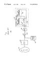
- FIG. 1 illustrates a prior art communications arrangement
- FIG. 2 is a plot describing the electrical characteristics of a first commercially available telephone which may be used in the arrangement of FIG. 1;
- FIG. 3 is a plot describing the electrical characteristics of a second commercially available telephone which may be used in the arrangement of FIG. 1;
- FIG. 4 illustrates a telephone network in accordance with the invention in customer premises
- FIG. 5 illustrates a connector used in a connection in the telephone network of FIG. 4, which includes a balancing network in accordance with the invention.
- FIG. 1 illustrates prior art communications arrangement 100 where customer premises 110 , e.g., a home, is provided with a communications line, e.g., telephone line 117 for voice communications.
- Telephone line 117 comprises a pair of copper wires, denoted 117 a and 117 b , forming a two-way communication path.
- Wire 117 a conventionally referred to as a “TIP” lead, normally assumes a higher electric potential with respect to wire 117 b , conventionally referred to as a “RING” lead.
- Telephone line 117 connects communication apparatuses, for example, telephones 119 and 121 , to public switched telephone network (PSTN) 101 to realize the voice communications.
- PSTN public switched telephone network
- coaxial cable 135 which runs from central office 105 , serving as a gateway to PSTN 101 , is used to transport the voice communications.
- Cable 135 is terminated at network interface unit (NIU) 139 outside customer premises 110 from which telephone line 117 extends into premises 110 .
- NIU network interface unit
- coaxial cable 135 is also used to transport CATV signals.
- CATV cable television
- a CATV line providing the CATV service and a telephone line in addition to telephone line 117 extend from NIU 139 into customer premises 110 , these additional lines, however, are not shown in FIG. 1 .
- central office 105 receives the CATV signals via, e.g., satellites, and causes the signals to populate a pre-assigned frequency band on cable 135 , which is separate from the frequency bands occupied by the voice communications.
- power node 141 is used to provide, through power line 147 , loop current to the telephone lines including telephone line 117 in premises 110 .
- the loop current available for each telephone line is limited. In this illustration, the loop current limit is about 22 mA.
- multiple telephones including telephones 119 and 121 are connected to telephone line 117 in a parallel manner.
- any one of telephones 119 and 121 is in use, and conducts electricity, known as an “off-hook” condition, it draws loop current from telephone line 117 for voice communications.
- connected to the same telephone line 117 are two different, commercially available telephones 119 and 121 , which is common.
- telephone 119 possesses electrical characteristics described in FIG. 2, which is a plot of the operating voltage and resistance of telephone 119 versus the loop current drawn thereby when it is in an off-hook condition. As shown in FIG. 2, the resistance of telephone 119 varies with the loop current drawn. Specifically, the higher the loop current, the lower is the resistance. The resulting operating voltage, however, increases with the loop current.
- telephone 121 possesses electrical characteristics described in FIG. 3, which is a plot of the operating voltage and resistance of telephone 121 versus the loop current drawn thereby when it is in an off-hook condition. As shown in FIG. 3, unlike the resistance of telephone 119 , the resistance of telephone 121 varies slightly with the loop current drawn. As a result, the operating voltage increases directly with the loop current.
- each of the off-hook telephones draws loop current from the telephone line.
- telephone 119 draws only 0.97 mA of the total loop current, and operates with a resistance of 3,753 Ohms and at a voltage of 3.64 V, in accordance with its electrical characteristics of FIG. 2 .
- telephone 121 with a resistance of 172 Ohms, however seizes the bulk of the loop current, i.e., 21.20 mA, in accordance with its electrical characteristics of FIG. 3 .
- telephone 121 has more than sufficient loop current to drive its circuitry to effect the normal voice and touch tone operation.
- telephone 119 has insufficient loop current to drive its circuitry, causing its audio level to be significantly lower than the desired level.
- the user of telephone 119 can hardly hear the telephone conversation (or, for that matter, its dial tone also) and meaningfully participate in same.
- these loads in this instance include loads 151 and 153 , which comprise telephone 121 contributing a resistance of 172 Ohms and telephone 119 contributing a resistance of 3,753 Ohms, respectively, and are connected in parallel to telephone line 117 .
- a balancing network is used to balance such loads to more evenly distribute the loop current supply to the telephones.
- FIG. 4 illustrates a telephone network in customer premises 410 embodying the principles of the invention.
- the telephone network in customer premises 410 is similar to that in customer premises 110 described before, except that the former includes balancing network 415 in accordance with the invention.
- balancing network 415 comprises a pair of resistors, denoted 417 and 419 .
- Resistors 417 and 419 are connected in series with the telephone having the least operating resistance (i.e., telephone 121 in this instance) when each telephone connected to the same telephone line is off-hook. That is, in this instance, resistor 417 is connected at its one end to telephone 121 through lead 441 , and at its other end to wire 117 a through lead 431 .
- resistor 419 is connected at its one end to telephone 121 through lead 443 , and at its other end to wire 117 b through lead 433 .
- the telephone having the least operating resistance can be identified by detecting any drop in its audio level when each other telephone connected to the same telephone line is off-hook. The drop, if any, should be the least compared with that of each other telephone.
- the values of resistors 417 and 419 in this instance are each 86.6 Ohms.
- the total loop current drawn by both telephones 119 and 121 in an off-hook condition is 21.63 mA (vs. 22.17 mA before).
- telephone 119 here operates with a resistance of 295 Ohms (vs. 3,753 Ohms before) and at a voltage of 4.72 V (vs. 3.64 V before), and draws 7.97 mA (vs. 0.97 mA before) loop current, in accordance with the electrical characteristics of FIG. 2 .
- telephone 121 operates with a resistance of 172 Ohms (same as before) and at a voltage of 2.35 V (vs. 3.64 V before), and draws 13.66 mA (vs. 21.20 mA before) loop current, in accordance with the electrical characteristics of FIG. 3 .
- load 451 and 453 which are connected in parallel to telephone line 117 , become relatively balanced, with respect to loads 151 and 153 described before.
- Load 453 including telephone 119 only has a resistance of 295 Ohms.
- telephones 119 and 121 in customer premises 410 are afforded a more balanced proportion of the loop current from telephone line 117 , with respect to those in customer premises 110 .
- telephone 119 has much more current to drive its circuitry, and its audio level is accordingly improved.
- balancing network 415 in accordance with the invention may be incorporated in a conventional double female RJ-8 connector.
- the resulting connector, denoted 500 is illustrated in FIG. 5 .
- Connector 500 is similar to the conventional connector, except that female modular jacks 503 and 507 in connector 500 are no longer connected to each other by conductors as in the conventional connector. Rather, in accordance with the invention, female modular jack 503 is connected to female modular jack 507 through resistors 417 and 419 constituting balancing network 415 .
- Each resistor may be a metal film resistor with a shrink tubing covering for insulation.
- conventional male modular jack 533 in FIG. 5 connected to leads 431 and 433 may be used to mate with female modular jack 503 in connector 500 while conventional male modular jack 537 connected to leads 441 and 443 may be used to mate with female modular jack 507 in same.
- the inventive balancing network is illustratively connected to the telephone having a smaller operating resistance when both telephones are off-hook.
- the invention is equally applicable to where more than two telephones are connected to the same telephone line. In that case, one or more of the telephones having smaller operating resistances can each be connected to the inventive balancing network.
- balancing network 415 illustratively comprises resistors.
- the make-up of the balancing network is not so limited.
- the balancing network comprises one or more electrical circuits and/or devices which affect the resistance of at least one of the loads connected in parallel to a telephone line to balance loop current supplies to the telephones constituting at least part of the loads.
Landscapes
- Engineering & Computer Science (AREA)
- Signal Processing (AREA)
- Telephonic Communication Services (AREA)
Abstract
Description
Claims (17)
Priority Applications (1)
| Application Number | Priority Date | Filing Date | Title |
|---|---|---|---|
| US09/019,454 US6259788B1 (en) | 1998-02-05 | 1998-02-05 | Technique for balancing loads in a communication network |
Applications Claiming Priority (1)
| Application Number | Priority Date | Filing Date | Title |
|---|---|---|---|
| US09/019,454 US6259788B1 (en) | 1998-02-05 | 1998-02-05 | Technique for balancing loads in a communication network |
Publications (1)
| Publication Number | Publication Date |
|---|---|
| US6259788B1 true US6259788B1 (en) | 2001-07-10 |
Family
ID=21793309
Family Applications (1)
| Application Number | Title | Priority Date | Filing Date |
|---|---|---|---|
| US09/019,454 Expired - Lifetime US6259788B1 (en) | 1998-02-05 | 1998-02-05 | Technique for balancing loads in a communication network |
Country Status (1)
| Country | Link |
|---|---|
| US (1) | US6259788B1 (en) |
Citations (1)
| Publication number | Priority date | Publication date | Assignee | Title |
|---|---|---|---|---|
| US5802152A (en) * | 1995-07-13 | 1998-09-01 | Delaine, Jr.; Phillip M. | Modem speed dialer circuit |
-
1998
- 1998-02-05 US US09/019,454 patent/US6259788B1/en not_active Expired - Lifetime
Patent Citations (1)
| Publication number | Priority date | Publication date | Assignee | Title |
|---|---|---|---|---|
| US5802152A (en) * | 1995-07-13 | 1998-09-01 | Delaine, Jr.; Phillip M. | Modem speed dialer circuit |
Similar Documents
| Publication | Publication Date | Title |
|---|---|---|
| US7684557B2 (en) | System and method of delivering DSL services | |
| US6385315B1 (en) | Video voice separation system | |
| US7742397B2 (en) | System and method of providing DSL services on a telephone networks | |
| US20100316101A1 (en) | Cross connect block | |
| US6970534B1 (en) | Methods and test sets for testing multi-line telecommunications service | |
| US9025744B2 (en) | System for providing telephony and data services | |
| US6535579B1 (en) | Network interface device with disconnectable half-ringer | |
| US6259788B1 (en) | Technique for balancing loads in a communication network | |
| US7706526B2 (en) | Method and apparatus for powering electronics associated with a telephone line twisted pair | |
| US6449362B1 (en) | Apparatus, systems and methods for isolating ADSL signals from POTS signals | |
| US7027587B2 (en) | System and method for deriving sealing current | |
| US20060045258A1 (en) | Method and apparatus for improved data and video delivery | |
| US20020106075A1 (en) | Direct electrical connectability of port of splitter unit to connector of interface circuit of switch | |
| US20040102071A1 (en) | Modular telephone jack for multi-occupant dwelling | |
| US20120263295A1 (en) | Active microfilter for vdsl2 communication standard | |
| US6975620B2 (en) | Coupling of splitter with subset of plurality of lines on one-to-one basis | |
| CA1175171A (en) | Testing facility for telephone conference bridge | |
| CN101248653B (en) | Method and device for checking the connection of a positive supply voltage to a subscriber access line comprising a plurality of wires | |
| Hawley et al. | Loop plant electronics: Voice frequency electronics for loop applications | |
| AU2003200045B2 (en) | Asymmetric Digital Subscriber Line (ADSL) Filter | |
| US20070211886A1 (en) | Phone converter system | |
| Golden et al. | Overview of the POTS Environment—Signals and Circuits | |
| JPH02165758A (en) | Isdn network terminating equipment | |
| JP2000253104A (en) | Branch unit and wiring method using the branch unit | |
| SE522828C2 (en) | Internet telephone interference reduction technique includes internet coupling, with electronic circuits and interphone (IP) gateway data |
Legal Events
| Date | Code | Title | Description |
|---|---|---|---|
| AS | Assignment |
Owner name: LUCENT TECHNOLOGIES INC., NEW JERSEY Free format text: ASSIGNMENT OF ASSIGNORS INTEREST;ASSIGNOR:CARUSO, JOHN T.;REEL/FRAME:008957/0415 Effective date: 19980204 |
|
| STCF | Information on status: patent grant |
Free format text: PATENTED CASE |
|
| FPAY | Fee payment |
Year of fee payment: 4 |
|
| FEPP | Fee payment procedure |
Free format text: PAYOR NUMBER ASSIGNED (ORIGINAL EVENT CODE: ASPN); ENTITY STATUS OF PATENT OWNER: LARGE ENTITY |
|
| FPAY | Fee payment |
Year of fee payment: 8 |
|
| FPAY | Fee payment |
Year of fee payment: 12 |
|
| AS | Assignment |
Owner name: CREDIT SUISSE AG, NEW YORK Free format text: SECURITY INTEREST;ASSIGNOR:ALCATEL-LUCENT USA INC.;REEL/FRAME:030510/0627 Effective date: 20130130 |
|
| AS | Assignment |
Owner name: ALCATEL-LUCENT USA INC., NEW JERSEY Free format text: RELEASE BY SECURED PARTY;ASSIGNOR:CREDIT SUISSE AG;REEL/FRAME:033949/0531 Effective date: 20140819 |
|
| AS | Assignment |
Owner name: OMEGA CREDIT OPPORTUNITIES MASTER FUND, LP, NEW YORK Free format text: SECURITY INTEREST;ASSIGNOR:WSOU INVESTMENTS, LLC;REEL/FRAME:043966/0574 Effective date: 20170822 Owner name: OMEGA CREDIT OPPORTUNITIES MASTER FUND, LP, NEW YO Free format text: SECURITY INTEREST;ASSIGNOR:WSOU INVESTMENTS, LLC;REEL/FRAME:043966/0574 Effective date: 20170822 |
|
| AS | Assignment |
Owner name: WSOU INVESTMENTS, LLC, CALIFORNIA Free format text: ASSIGNMENT OF ASSIGNORS INTEREST;ASSIGNOR:ALCATEL LUCENT;REEL/FRAME:044000/0053 Effective date: 20170722 |
|
| AS | Assignment |
Owner name: WSOU INVESTMENTS, LLC, CALIFORNIA Free format text: RELEASE BY SECURED PARTY;ASSIGNOR:OCO OPPORTUNITIES MASTER FUND, L.P. (F/K/A OMEGA CREDIT OPPORTUNITIES MASTER FUND LP;REEL/FRAME:049246/0405 Effective date: 20190516 |
|
| AS | Assignment |
Owner name: OT WSOU TERRIER HOLDINGS, LLC, CALIFORNIA Free format text: SECURITY INTEREST;ASSIGNOR:WSOU INVESTMENTS, LLC;REEL/FRAME:056990/0081 Effective date: 20210528 |