US6255620B1 - Filter bag assembly line and method - Google Patents
Filter bag assembly line and method Download PDFInfo
- Publication number
- US6255620B1 US6255620B1 US09/301,931 US30193199A US6255620B1 US 6255620 B1 US6255620 B1 US 6255620B1 US 30193199 A US30193199 A US 30193199A US 6255620 B1 US6255620 B1 US 6255620B1
- Authority
- US
- United States
- Prior art keywords
- tube
- welding
- filter
- filter bag
- ring
- Prior art date
- Legal status (The legal status is an assumption and is not a legal conclusion. Google has not performed a legal analysis and makes no representation as to the accuracy of the status listed.)
- Expired - Lifetime
Links
Images


Classifications
-
- B—PERFORMING OPERATIONS; TRANSPORTING
- B29—WORKING OF PLASTICS; WORKING OF SUBSTANCES IN A PLASTIC STATE IN GENERAL
- B29C—SHAPING OR JOINING OF PLASTICS; SHAPING OF MATERIAL IN A PLASTIC STATE, NOT OTHERWISE PROVIDED FOR; AFTER-TREATMENT OF THE SHAPED PRODUCTS, e.g. REPAIRING
- B29C66/00—General aspects of processes or apparatus for joining preformed parts
- B29C66/40—General aspects of joining substantially flat articles, e.g. plates, sheets or web-like materials; Making flat seams in tubular or hollow articles; Joining single elements to substantially flat surfaces
- B29C66/41—Joining substantially flat articles ; Making flat seams in tubular or hollow articles
- B29C66/43—Joining a relatively small portion of the surface of said articles
-
- B—PERFORMING OPERATIONS; TRANSPORTING
- B23—MACHINE TOOLS; METAL-WORKING NOT OTHERWISE PROVIDED FOR
- B23K—SOLDERING OR UNSOLDERING; WELDING; CLADDING OR PLATING BY SOLDERING OR WELDING; CUTTING BY APPLYING HEAT LOCALLY, e.g. FLAME CUTTING; WORKING BY LASER BEAM
- B23K26/00—Working by laser beam, e.g. welding, cutting or boring
- B23K26/08—Devices involving relative movement between laser beam and workpiece
- B23K26/083—Devices involving movement of the workpiece in at least one axial direction
- B23K26/0838—Devices involving movement of the workpiece in at least one axial direction by using an endless conveyor belt
-
- B—PERFORMING OPERATIONS; TRANSPORTING
- B29—WORKING OF PLASTICS; WORKING OF SUBSTANCES IN A PLASTIC STATE IN GENERAL
- B29C—SHAPING OR JOINING OF PLASTICS; SHAPING OF MATERIAL IN A PLASTIC STATE, NOT OTHERWISE PROVIDED FOR; AFTER-TREATMENT OF THE SHAPED PRODUCTS, e.g. REPAIRING
- B29C65/00—Joining or sealing of preformed parts, e.g. welding of plastics materials; Apparatus therefor
- B29C65/02—Joining or sealing of preformed parts, e.g. welding of plastics materials; Apparatus therefor by heating, with or without pressure
- B29C65/06—Joining or sealing of preformed parts, e.g. welding of plastics materials; Apparatus therefor by heating, with or without pressure using friction, e.g. spin welding
-
- B—PERFORMING OPERATIONS; TRANSPORTING
- B29—WORKING OF PLASTICS; WORKING OF SUBSTANCES IN A PLASTIC STATE IN GENERAL
- B29C—SHAPING OR JOINING OF PLASTICS; SHAPING OF MATERIAL IN A PLASTIC STATE, NOT OTHERWISE PROVIDED FOR; AFTER-TREATMENT OF THE SHAPED PRODUCTS, e.g. REPAIRING
- B29C65/00—Joining or sealing of preformed parts, e.g. welding of plastics materials; Apparatus therefor
- B29C65/02—Joining or sealing of preformed parts, e.g. welding of plastics materials; Apparatus therefor by heating, with or without pressure
- B29C65/08—Joining or sealing of preformed parts, e.g. welding of plastics materials; Apparatus therefor by heating, with or without pressure using ultrasonic vibrations
- B29C65/083—Joining or sealing of preformed parts, e.g. welding of plastics materials; Apparatus therefor by heating, with or without pressure using ultrasonic vibrations using a rotary sonotrode or a rotary anvil
- B29C65/086—Joining or sealing of preformed parts, e.g. welding of plastics materials; Apparatus therefor by heating, with or without pressure using ultrasonic vibrations using a rotary sonotrode or a rotary anvil using a rotary anvil
-
- B—PERFORMING OPERATIONS; TRANSPORTING
- B29—WORKING OF PLASTICS; WORKING OF SUBSTANCES IN A PLASTIC STATE IN GENERAL
- B29C—SHAPING OR JOINING OF PLASTICS; SHAPING OF MATERIAL IN A PLASTIC STATE, NOT OTHERWISE PROVIDED FOR; AFTER-TREATMENT OF THE SHAPED PRODUCTS, e.g. REPAIRING
- B29C65/00—Joining or sealing of preformed parts, e.g. welding of plastics materials; Apparatus therefor
- B29C65/78—Means for handling the parts to be joined, e.g. for making containers or hollow articles, e.g. means for handling sheets, plates, web-like materials, tubular articles, hollow articles or elements to be joined therewith; Means for discharging the joined articles from the joining apparatus
- B29C65/7858—Means for handling the parts to be joined, e.g. for making containers or hollow articles, e.g. means for handling sheets, plates, web-like materials, tubular articles, hollow articles or elements to be joined therewith; Means for discharging the joined articles from the joining apparatus characterised by the feeding movement of the parts to be joined
- B29C65/7879—Means for handling the parts to be joined, e.g. for making containers or hollow articles, e.g. means for handling sheets, plates, web-like materials, tubular articles, hollow articles or elements to be joined therewith; Means for discharging the joined articles from the joining apparatus characterised by the feeding movement of the parts to be joined said parts to be joined moving in a closed path, e.g. a rectangular path
- B29C65/7882—Means for handling the parts to be joined, e.g. for making containers or hollow articles, e.g. means for handling sheets, plates, web-like materials, tubular articles, hollow articles or elements to be joined therewith; Means for discharging the joined articles from the joining apparatus characterised by the feeding movement of the parts to be joined said parts to be joined moving in a closed path, e.g. a rectangular path said parts to be joined moving in a circular path
-
- B—PERFORMING OPERATIONS; TRANSPORTING
- B29—WORKING OF PLASTICS; WORKING OF SUBSTANCES IN A PLASTIC STATE IN GENERAL
- B29C—SHAPING OR JOINING OF PLASTICS; SHAPING OF MATERIAL IN A PLASTIC STATE, NOT OTHERWISE PROVIDED FOR; AFTER-TREATMENT OF THE SHAPED PRODUCTS, e.g. REPAIRING
- B29C66/00—General aspects of processes or apparatus for joining preformed parts
- B29C66/01—General aspects dealing with the joint area or with the area to be joined
- B29C66/05—Particular design of joint configurations
- B29C66/10—Particular design of joint configurations particular design of the joint cross-sections
- B29C66/11—Joint cross-sections comprising a single joint-segment, i.e. one of the parts to be joined comprising a single joint-segment in the joint cross-section
- B29C66/112—Single lapped joints
- B29C66/1122—Single lap to lap joints, i.e. overlap joints
-
- B—PERFORMING OPERATIONS; TRANSPORTING
- B29—WORKING OF PLASTICS; WORKING OF SUBSTANCES IN A PLASTIC STATE IN GENERAL
- B29C—SHAPING OR JOINING OF PLASTICS; SHAPING OF MATERIAL IN A PLASTIC STATE, NOT OTHERWISE PROVIDED FOR; AFTER-TREATMENT OF THE SHAPED PRODUCTS, e.g. REPAIRING
- B29C66/00—General aspects of processes or apparatus for joining preformed parts
- B29C66/01—General aspects dealing with the joint area or with the area to be joined
- B29C66/05—Particular design of joint configurations
- B29C66/20—Particular design of joint configurations particular design of the joint lines, e.g. of the weld lines
- B29C66/24—Particular design of joint configurations particular design of the joint lines, e.g. of the weld lines said joint lines being closed or non-straight
- B29C66/244—Particular design of joint configurations particular design of the joint lines, e.g. of the weld lines said joint lines being closed or non-straight said joint lines being non-straight, e.g. forming non-closed contours
-
- B—PERFORMING OPERATIONS; TRANSPORTING
- B29—WORKING OF PLASTICS; WORKING OF SUBSTANCES IN A PLASTIC STATE IN GENERAL
- B29C—SHAPING OR JOINING OF PLASTICS; SHAPING OF MATERIAL IN A PLASTIC STATE, NOT OTHERWISE PROVIDED FOR; AFTER-TREATMENT OF THE SHAPED PRODUCTS, e.g. REPAIRING
- B29C66/00—General aspects of processes or apparatus for joining preformed parts
- B29C66/01—General aspects dealing with the joint area or with the area to be joined
- B29C66/345—Progressively making the joint, e.g. starting from the middle
- B29C66/3452—Making complete joints by combining partial joints
-
- B—PERFORMING OPERATIONS; TRANSPORTING
- B29—WORKING OF PLASTICS; WORKING OF SUBSTANCES IN A PLASTIC STATE IN GENERAL
- B29C—SHAPING OR JOINING OF PLASTICS; SHAPING OF MATERIAL IN A PLASTIC STATE, NOT OTHERWISE PROVIDED FOR; AFTER-TREATMENT OF THE SHAPED PRODUCTS, e.g. REPAIRING
- B29C66/00—General aspects of processes or apparatus for joining preformed parts
- B29C66/40—General aspects of joining substantially flat articles, e.g. plates, sheets or web-like materials; Making flat seams in tubular or hollow articles; Joining single elements to substantially flat surfaces
- B29C66/41—Joining substantially flat articles ; Making flat seams in tubular or hollow articles
- B29C66/43—Joining a relatively small portion of the surface of said articles
- B29C66/431—Joining the articles to themselves
- B29C66/4312—Joining the articles to themselves for making flat seams in tubular or hollow articles, e.g. transversal seams
-
- B—PERFORMING OPERATIONS; TRANSPORTING
- B29—WORKING OF PLASTICS; WORKING OF SUBSTANCES IN A PLASTIC STATE IN GENERAL
- B29C—SHAPING OR JOINING OF PLASTICS; SHAPING OF MATERIAL IN A PLASTIC STATE, NOT OTHERWISE PROVIDED FOR; AFTER-TREATMENT OF THE SHAPED PRODUCTS, e.g. REPAIRING
- B29C66/00—General aspects of processes or apparatus for joining preformed parts
- B29C66/80—General aspects of machine operations or constructions and parts thereof
- B29C66/83—General aspects of machine operations or constructions and parts thereof characterised by the movement of the joining or pressing tools
- B29C66/832—Reciprocating joining or pressing tools
- B29C66/8322—Joining or pressing tools reciprocating along one axis
- B29C66/83221—Joining or pressing tools reciprocating along one axis cooperating reciprocating tools, each tool reciprocating along one axis
-
- B—PERFORMING OPERATIONS; TRANSPORTING
- B29—WORKING OF PLASTICS; WORKING OF SUBSTANCES IN A PLASTIC STATE IN GENERAL
- B29C—SHAPING OR JOINING OF PLASTICS; SHAPING OF MATERIAL IN A PLASTIC STATE, NOT OTHERWISE PROVIDED FOR; AFTER-TREATMENT OF THE SHAPED PRODUCTS, e.g. REPAIRING
- B29C66/00—General aspects of processes or apparatus for joining preformed parts
- B29C66/80—General aspects of machine operations or constructions and parts thereof
- B29C66/84—Specific machine types or machines suitable for specific applications
- B29C66/851—Bag or container making machines
- B29C66/8511—Bag making machines
-
- B—PERFORMING OPERATIONS; TRANSPORTING
- B29—WORKING OF PLASTICS; WORKING OF SUBSTANCES IN A PLASTIC STATE IN GENERAL
- B29C—SHAPING OR JOINING OF PLASTICS; SHAPING OF MATERIAL IN A PLASTIC STATE, NOT OTHERWISE PROVIDED FOR; AFTER-TREATMENT OF THE SHAPED PRODUCTS, e.g. REPAIRING
- B29C66/00—General aspects of processes or apparatus for joining preformed parts
- B29C66/90—Measuring or controlling the joining process
- B29C66/98—Determining the joining area by using markings on at least one of the parts to be joined
-
- B—PERFORMING OPERATIONS; TRANSPORTING
- B31—MAKING ARTICLES OF PAPER, CARDBOARD OR MATERIAL WORKED IN A MANNER ANALOGOUS TO PAPER; WORKING PAPER, CARDBOARD OR MATERIAL WORKED IN A MANNER ANALOGOUS TO PAPER
- B31B—MAKING CONTAINERS OF PAPER, CARDBOARD OR MATERIAL WORKED IN A MANNER ANALOGOUS TO PAPER
- B31B70/00—Making flexible containers, e.g. envelopes or bags
- B31B70/60—Uniting opposed surfaces or edges; Taping
- B31B70/64—Uniting opposed surfaces or edges; Taping by applying heat or pressure
-
- B—PERFORMING OPERATIONS; TRANSPORTING
- B23—MACHINE TOOLS; METAL-WORKING NOT OTHERWISE PROVIDED FOR
- B23K—SOLDERING OR UNSOLDERING; WELDING; CLADDING OR PLATING BY SOLDERING OR WELDING; CUTTING BY APPLYING HEAT LOCALLY, e.g. FLAME CUTTING; WORKING BY LASER BEAM
- B23K2103/00—Materials to be soldered, welded or cut
- B23K2103/30—Organic material
- B23K2103/42—Plastics
-
- B—PERFORMING OPERATIONS; TRANSPORTING
- B23—MACHINE TOOLS; METAL-WORKING NOT OTHERWISE PROVIDED FOR
- B23K—SOLDERING OR UNSOLDERING; WELDING; CLADDING OR PLATING BY SOLDERING OR WELDING; CUTTING BY APPLYING HEAT LOCALLY, e.g. FLAME CUTTING; WORKING BY LASER BEAM
- B23K2103/00—Materials to be soldered, welded or cut
- B23K2103/50—Inorganic material, e.g. metals, not provided for in B23K2103/02 – B23K2103/26
-
- B—PERFORMING OPERATIONS; TRANSPORTING
- B29—WORKING OF PLASTICS; WORKING OF SUBSTANCES IN A PLASTIC STATE IN GENERAL
- B29C—SHAPING OR JOINING OF PLASTICS; SHAPING OF MATERIAL IN A PLASTIC STATE, NOT OTHERWISE PROVIDED FOR; AFTER-TREATMENT OF THE SHAPED PRODUCTS, e.g. REPAIRING
- B29C2791/00—Shaping characteristics in general
- B29C2791/004—Shaping under special conditions
- B29C2791/009—Using laser
-
- B—PERFORMING OPERATIONS; TRANSPORTING
- B29—WORKING OF PLASTICS; WORKING OF SUBSTANCES IN A PLASTIC STATE IN GENERAL
- B29C—SHAPING OR JOINING OF PLASTICS; SHAPING OF MATERIAL IN A PLASTIC STATE, NOT OTHERWISE PROVIDED FOR; AFTER-TREATMENT OF THE SHAPED PRODUCTS, e.g. REPAIRING
- B29C2793/00—Shaping techniques involving a cutting or machining operation
- B29C2793/009—Shaping techniques involving a cutting or machining operation after shaping
-
- B—PERFORMING OPERATIONS; TRANSPORTING
- B29—WORKING OF PLASTICS; WORKING OF SUBSTANCES IN A PLASTIC STATE IN GENERAL
- B29C—SHAPING OR JOINING OF PLASTICS; SHAPING OF MATERIAL IN A PLASTIC STATE, NOT OTHERWISE PROVIDED FOR; AFTER-TREATMENT OF THE SHAPED PRODUCTS, e.g. REPAIRING
- B29C65/00—Joining or sealing of preformed parts, e.g. welding of plastics materials; Apparatus therefor
- B29C65/74—Joining or sealing of preformed parts, e.g. welding of plastics materials; Apparatus therefor by welding and severing, or by joining and severing, the severing being performed in the area to be joined, next to the area to be joined, in the joint area or next to the joint area
- B29C65/749—Removing scrap
-
- B—PERFORMING OPERATIONS; TRANSPORTING
- B29—WORKING OF PLASTICS; WORKING OF SUBSTANCES IN A PLASTIC STATE IN GENERAL
- B29C—SHAPING OR JOINING OF PLASTICS; SHAPING OF MATERIAL IN A PLASTIC STATE, NOT OTHERWISE PROVIDED FOR; AFTER-TREATMENT OF THE SHAPED PRODUCTS, e.g. REPAIRING
- B29C66/00—General aspects of processes or apparatus for joining preformed parts
- B29C66/80—General aspects of machine operations or constructions and parts thereof
- B29C66/83—General aspects of machine operations or constructions and parts thereof characterised by the movement of the joining or pressing tools
- B29C66/832—Reciprocating joining or pressing tools
- B29C66/8322—Joining or pressing tools reciprocating along one axis
-
- B—PERFORMING OPERATIONS; TRANSPORTING
- B29—WORKING OF PLASTICS; WORKING OF SUBSTANCES IN A PLASTIC STATE IN GENERAL
- B29C—SHAPING OR JOINING OF PLASTICS; SHAPING OF MATERIAL IN A PLASTIC STATE, NOT OTHERWISE PROVIDED FOR; AFTER-TREATMENT OF THE SHAPED PRODUCTS, e.g. REPAIRING
- B29C66/00—General aspects of processes or apparatus for joining preformed parts
- B29C66/80—General aspects of machine operations or constructions and parts thereof
- B29C66/84—Specific machine types or machines suitable for specific applications
- B29C66/841—Machines or tools adaptable for making articles of different dimensions or shapes or for making joints of different dimensions
- B29C66/8412—Machines or tools adaptable for making articles of different dimensions or shapes or for making joints of different dimensions of different length, width or height
- B29C66/84123—Machines or tools adaptable for making articles of different dimensions or shapes or for making joints of different dimensions of different length, width or height of different height
-
- B—PERFORMING OPERATIONS; TRANSPORTING
- B29—WORKING OF PLASTICS; WORKING OF SUBSTANCES IN A PLASTIC STATE IN GENERAL
- B29C—SHAPING OR JOINING OF PLASTICS; SHAPING OF MATERIAL IN A PLASTIC STATE, NOT OTHERWISE PROVIDED FOR; AFTER-TREATMENT OF THE SHAPED PRODUCTS, e.g. REPAIRING
- B29C66/00—General aspects of processes or apparatus for joining preformed parts
- B29C66/80—General aspects of machine operations or constructions and parts thereof
- B29C66/87—Auxiliary operations or devices
- B29C66/874—Safety measures or devices
- B29C66/8746—Detecting the absence of the articles to be joined
-
- B—PERFORMING OPERATIONS; TRANSPORTING
- B29—WORKING OF PLASTICS; WORKING OF SUBSTANCES IN A PLASTIC STATE IN GENERAL
- B29L—INDEXING SCHEME ASSOCIATED WITH SUBCLASS B29C, RELATING TO PARTICULAR ARTICLES
- B29L2031/00—Other particular articles
- B29L2031/14—Filters
-
- B—PERFORMING OPERATIONS; TRANSPORTING
- B29—WORKING OF PLASTICS; WORKING OF SUBSTANCES IN A PLASTIC STATE IN GENERAL
- B29L—INDEXING SCHEME ASSOCIATED WITH SUBCLASS B29C, RELATING TO PARTICULAR ARTICLES
- B29L2031/00—Other particular articles
- B29L2031/712—Containers; Packaging elements or accessories, Packages
- B29L2031/7128—Bags, sacks, sachets
-
- B—PERFORMING OPERATIONS; TRANSPORTING
- B31—MAKING ARTICLES OF PAPER, CARDBOARD OR MATERIAL WORKED IN A MANNER ANALOGOUS TO PAPER; WORKING PAPER, CARDBOARD OR MATERIAL WORKED IN A MANNER ANALOGOUS TO PAPER
- B31B—MAKING CONTAINERS OF PAPER, CARDBOARD OR MATERIAL WORKED IN A MANNER ANALOGOUS TO PAPER
- B31B2155/00—Flexible containers made from webs
- B31B2155/003—Flexible containers made from webs starting from tubular webs
-
- B—PERFORMING OPERATIONS; TRANSPORTING
- B31—MAKING ARTICLES OF PAPER, CARDBOARD OR MATERIAL WORKED IN A MANNER ANALOGOUS TO PAPER; WORKING PAPER, CARDBOARD OR MATERIAL WORKED IN A MANNER ANALOGOUS TO PAPER
- B31B—MAKING CONTAINERS OF PAPER, CARDBOARD OR MATERIAL WORKED IN A MANNER ANALOGOUS TO PAPER
- B31B2160/00—Shape of flexible containers
- B31B2160/30—Shape of flexible containers pointed or tapered
-
- B—PERFORMING OPERATIONS; TRANSPORTING
- B31—MAKING ARTICLES OF PAPER, CARDBOARD OR MATERIAL WORKED IN A MANNER ANALOGOUS TO PAPER; WORKING PAPER, CARDBOARD OR MATERIAL WORKED IN A MANNER ANALOGOUS TO PAPER
- B31B—MAKING CONTAINERS OF PAPER, CARDBOARD OR MATERIAL WORKED IN A MANNER ANALOGOUS TO PAPER
- B31B70/00—Making flexible containers, e.g. envelopes or bags
- B31B70/60—Uniting opposed surfaces or edges; Taping
Definitions
- the present invention relates to a filter bag assembly line and method, and, more particularly, to the portion of the assembly line and the assembly process from a station that forms the bag bottom through a station that attaches a support ring to the bag.
- One method of welding bag bottoms uses two pre-cut bag halves that are passed along a hot air welder. An operator inserts the hot air nozzle into the bag at a starting point; activates the hot air nozzle machine, softening each bag bottom half; places the semi-molten surfaces between a pair of driven nip rolls to seal the halves together; stops the machine once one side of the bag is welded; flips the bag over; and repeats the process for the other side of the bag.
- the bag has to be removed from the nozzle at a precise point, so that the nozzle will not damage the end of the bag. This process is slow, as it is entirely dependent upon the speed of the operator working the hot air nozzle machine, and results in poor quality welds having improperly aligned bag halves, loose fibers along the bottom edges of the bag due to the required pre-cutting, or welds of varying margins.
- a second method for welding bag bottoms is the hot plate-type method.
- a heated tong-type plate shaped to match the shape of the bottom of the bag, is inserted between the two layers of the bag bottom.
- the plate is withdrawn after the inner surfaces of the two halves have been slightly softened, and the halves are then pressed together to bond.
- This method is difficult to control, since the width of the bag must precisely match the width of the heated plate, which does not permit even slight variation of the bag width.
- Using an under-sized (i.e., narrow) bag will create damaged molten edges, while using an over-sized (i.e., wide) bag will create channels of unwelded sections along the bag bottom. Since controlling the bag width to close tolerances is difficult, this method is impractical to use.
- a third method of welding bag bottoms is the ultrasonic plunge welding method.
- a major disadvantage to this method is that each side of the bag has to be welded separately, since ultrasonic welding is not capable of welding components longer than twelve inches. The quality of the weld depends upon uniformity of the thickness and density of a given material, which varies widely with filtration media felts. Additionally, ultrasonic welding results in welds of a lesser strength than other methods, mainly due to the fact that energy is transferred from the outside of the bag to the interface of the two layers of the bag bottom, which requires excessive melting of the outer surface in order to achieve a strong weld at the interface of the two layers. Ultrasonic welding also has a tendency to cause embrittlement of the weld due to the high level of energy required in the welding process.
- the present invention involves a method for welding filter bag bottoms that is well-suited for use in a filter bag assembly line.
- a vibration welder By running two pre-formed filter tubes (each filter tube is the length of two completed bags, mated in an end-to-end configuration) side-by-side on two conveyor belts through a vibration welder and then through a laser cutter, a high-quality welded bag bottom is achieved.
- the present invention can simultaneously weld four bag bottoms of a truncated design in approximately 10 seconds, whereas the various prior art methods would require twelve welds to make four bag bottoms of a truncated design, and would take between 60 and 120 seconds to complete.
- the bag bottoms do not need to be pre-cut in order to be welded.
- the laser cutter separates the joined bags, and removes excess material along the truncated bag bottom.
- Using a laser cutter provides a glazed smooth edge, which is superior in appearance to a mechanically sheared cut, and leaves no loose fibers, which is an important feature for filters.
- the quality of the finished bag bottoms manufactured in accordance with the present invention is superior to that achieved using the prior art methods due to the degree of control possible through the use of the vibration welder and the laser cutter.
- the weld quality can be precisely controlled by using a machined vibration welding tool and by presetting the parameters of the weld (e.g., the force used, the frequency amplitude of the movement of the welding tool, and the melt-down parameters). Utilizing a non-contact laser is beneficial in that there is no need for heavy-duty cutting equipment and the maintenance associated with cutting equipment (i.e., no sharpening of knives or dies).
- FIG. 1 is a top plan view of the overall assembly line
- FIG. 2 is an enlarged top plan view of the vibration welding and laser cutting stations shown in FIG. 1;
- FIG. 3 is a top plan view of the welding tool used in the vibration welder shown in FIG. 2;
- FIG. 4 is a top plan view of the state of the bags as they pass through the vibration welding and laser cutting stations shown in FIG. 2;
- FIG. 5 is a diagrammatic view of the path of the laser cutter shown in FIG. 2;
- FIG. 6 is an enlarged top plan view of a modified configuration of the accumulation station and the ring welder stations shown in FIG. 1;
- FIG. 7 is a perspective view of an alternate configuration of the ring welder station shown in FIG. 6;
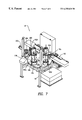
- FIG. 8 is a top view of the ring welder station shown in FIG. 7 .
- FIG. 1 shows the entire filter bag assembly line 10 .
- a front end section 12 consists of various conventional components arranged such that the front end section 12 begins with a single layer filtration media and ends with the media formed into filter tubes 14 .
- Each filter tube 14 is a folded-over piece of filtration media, hot-air seam welded along one edge to form a tube, and cut to twice the length of a finished filter bag.
- the tubes 14 are placed by an operator into an operator load station 16 . From the load station 16 , the tubes 14 pass into a vibration welding station 18 , where each tube 14 is welded midway between its ends, thereby forming two filter bags per tube 14 mated in a bottom-to-bottom configuration.
- a material handling section 20 removes the tubes 14 from the vibration welding station 18 and passes the tubes 14 into a laser cutting station 22 , where each tube 14 is cut into two filter bags 24 .
- a material handling section 26 removes the bags 24 from the laser cutting station 22 and passes the bags 24 to an accumulation station 28 .
- An operator removes a bag 24 from the accumulation station 28 and inserts it, along with a filter bag ring (not shown in FIG. 1 ), into the ring welder station 30 , which welds a ring onto each bag 24 , thereby completing the bag 24 .
- the configuration of the stations shown in FIG. 1 is one of several possible configurations for the overall layout of the assembly line 10 .
- four ring welder stations 30 are shown in FIG. 1, with the two ring welder stations 30 shown in phantom being locations for optional additional ring welder stations 30 .
- the accumulation station 28 could be extended such that more than the four ring welder stations 30 shown in FIG. 1 could be part of the assembly line 10 .
- the assembly line 10 is constructed to process two filter tubes 14 simultaneously in a side-by-side fashion on separate conveyors.
- the discussion of the progress of one tube 14 is equally applicable to the other tube 14 traveling along an adjacent conveyor.
- the filter tube 14 passes from the load station 16 (not shown in FIG. 2) onto a slider bed conveyor 32 .
- a pair of driven pinch rollers 34 grip above and below the tube 14 , passing the tube 14 into the vibration welding station 18 , which consists of a vibration welder 36 having a welding tool 38 which is shaped to conform to two truncated bag bottoms in a bottom-to-bottom, i.e., end-to-end, configuration (see FIG. 3 ).
- a photodetector 40 is located on the conveyor 32 before the vibration welder 36 and detects the leading edge of the tube 14 . When the leading edge of the tube 14 is detected, a servo motor 42 is activated.
- the servo motor 42 is used to properly center the tube 14 inside the vibration welder 36 by stopping the conveyor 32 when the pre-set length has been counted off.
- the servo motor 42 can be set for different length bags, without requiring any additional changes to the assembly line 10 . Once the servo motor 42 has centered the tube 14 , the vibration welder 36 is activated.
- the vibration welder 36 (such as Sonics & Materials Inc.'s model number EH4800) welds the center of the tube 14 with the welding tool 38 , forming the truncated bottom shape of two bags 24 joined together in a bottom-to-bottom configuration (see FIG. 4 ).
- the tube 14 has two triangular excess portions 44 (see FIG. 4) which join the two welded bags 24 together. Since the weld is formed at the joinder of two bags 24 and is approximately 0.625 inches wide, the welded tube 14 must be precisely cut along the center of the weld, else the bags 24 will be defective along the bottom edges thereof.
- a line (not shown) is drawn onto the bottom side of each of the excess portions 44 by an inkjet printer 46 (such as Dell's JetMarker printer) while the welded tube 14 is in the vibration welding station 18 .
- an inkjet printer 46 such as Dell's JetMarker printer
- the pinch rollers 34 are re-started, and the welded tube 14 is pulled out of the vibration welder 36 and onto a slider bed conveyor 48 of the material handling section 20 .
- a pair of driven pinch rollers 50 passes the welded tube 14 from the conveyor 48 into the laser cutting station 22 .
- a reflector 52 is located above the conveyor 48 before the laser cutting station 22 , and a photoelectric cell 54 is positioned below the reflector 52 .
- the reflector 52 and the photoelectric cell 54 are used in conjunction with the lines drawn on the bottom side of the excess portions 44 to stop the movement of the welded tube 14 through the laser cutting station 22 , thereby centering the welded tube 14 beneath a laser cutter 56 . While light from the reflector 52 passes through the passing welded tube 14 , the pinch rollers 50 are in operation, drawing the welded tube 14 through the laser cutting station 22 .
- the photoelectric cell 54 detects the dark line and activates a servo motor 55 , which counts off the proper length of the bag relative to the line, to thereby center the welded tube 14 beneath the laser cutter 56 .
- the inkjet printer 46 could be replaced with a hole punch, which would punch a hole through the excess portions 44 .
- the hole would be detected by the reflector 52 and the photoelectric cell 54 in a similar manner as the line, and the operation of this portion of the assembly line 10 would remain unchanged.
- the laser cutter 56 (such as Jamieson Manufacturing Co. Inc.'s model number LC2) is a standard programmable X-Y table laser, which cuts the welded tube 14 into two separate bags 24 along the welded bag bottom.
- the laser cutter 56 cuts the tubes 14 on both of the conveyor belts during each pass of the laser.
- the cutting pattern is shown in FIG. 5 .
- the laser cutter 56 moves between the lettered positions as follows: A - B - C - D - E - F - D - C - G - H - I - J - K - L - M - K - J - N - A.
- the triangular excess portions 44 (see FIG. 4) are trimmed away, leaving a smoothly cut, truncated bag bottom.
- each bag 24 is left with one opening, a mouth, located at an end of the bag 24 opposite the welded bottom.
- the triangular excess portions 44 are removed from the laser cutter 56 by a trimmed pieces removal device 58 , onto a take-away conveyor 60 , and into a collection bin 62 . By locating the collection bin 62 away from the laser cutter 56 , the excess portions 44 can be removed and disposed of without interrupting the assembly line 10 .
- the pinch rollers 50 are re-started, and the bags 24 are removed from the laser cutting station 22 via a slider bed conveyor 64 of the material handling section 26 and are transported to the accumulation station 28 .
- FIG. 6 shows alternative configurations for the accumulation station 28 and the ring welder stations 30 than those depicted in FIG. 1 .
- the key difference between the alternative configurations is that in FIG. 1, the welding machines of the ring welder stations 30 are shown at 180° spacing, whereas in FIG. 6, the welding machines are shown at 90° spacing.
- the alternative stations shown in FIG. 6 have been designated with prime reference numerals (i.e., accumulation station 28 ′ and ring welder stations 30 ′).
- a stacker infeed conveyor 66 takes the bags 24 from the material handling section 26 (see FIG. 1) and passes the bags 24 to a stacking device 68 , which stacks the bags 24 into eight inch high stacks 70 .
- a stacker accumulator conveyor 72 removes the completed stacks 70 from the stacking device 68 and places the stacks 70 in a location convenient for the operators of the ring welder stations 30 ′ to be able to access the stacks 70 .
- Each ring welder station 30 ′ has a machine base 74 , on which two sonic welders 76 a, 76 b (such as Sonics & Materials, Inc.'s model number 1096S) are mounted at 90° spacing.
- An indexing table 78 is rotatably positioned on the machine base 74 and has four positions 80 a-d.
- the indexing table 78 also has four mandrels 82 a-d, each mandrel 82 having an associated set of alignment fixtures 84 .
- Each mandrel 82 is constructed such that it, along with its associated alignment fixtures 84 , can be rotated in place, independently of the indexing table 78 .
- the mandrels 82 a-d are located at positions 80 a-d, with each mandrel 82 capable of being indexed by the indexing table 78 through each of the positions 80 a-d.
- each of the ring welder stations 30 ′ functions as follows.
- An operator 86 places a ring 88 onto the mandrel 82 a located at position 80 a, in front of an access opening 90 .
- the operator 86 then takes a bag 24 (not shown) from one of the stacks 70 and places the bag 24 upside down onto the mandrel 82 a, such that the mouth of the bag 24 surrounds the ring 88 .
- the indexing table 78 is rotated 90° clockwise, so that the mandrel 82 a carrying the bag 24 and ring 88 is at position 80 b, in front of sonic welder 76 a, which welds the bag 24 to the ring 88 along a 60° arc.
- the mandrel 82 a at position 80 b is rotated in place by 60°, and the sonic welder 76 a then welds the bag 24 to the ring 88 along a second 60° arc.
- the mandrel 82 a at position 80 b is again rotated in place by 60°, and the sonic welder 76 a welds the bag 24 to the ring 88 along a third 60° arc.
- the result of the alternating welding and rotating phases being that the sonic welder 76 a welds the first 180° of the bag 24 to the ring 88 in three successive 60° arcs.
- the indexing table 78 is next rotated 90° clockwise such that the mandrel 82 a carrying the partially welded bag 24 and ring 88 is at position 80 c, in front of sonic welder 76 b.
- the operation of the sonic welder 76 b is the same as the sonic welder 76 a, with the exception being that the mandrel 82 a carrying the bag 24 and ring 88 is rotated in place by 60° first, then welded in a 60° arc, thereby welding the remaining 180° of the bag 24 to the ring 88 in 60° increments.
- the sequence of welding and rotating is purposely out of synch between the sonic welders 76 a, 76 b so that both welders are never firing at the same time.
- This alternative welding eliminates any potential interference problems between the two welders 76 a, 76 b and also minimizes the peak power draw.
- the indexing table 78 is rotated another 90° clockwise such that the mandrel 82 a carrying the completely welded bag 24 and ring 88 is at position 80 d.
- the indexing table 78 stays in this position until the welding of two other bags at positions 80 b and 80 c is completed.
- the indexing table is then rotated a final 90° such that the mandrel 82 a carrying the completely welded bag 24 and ring 88 is at position 80 a, where the completely welded bag 24 and ring 88 can be unloaded by the operator 86 through the access opening 90 .
- the entire cycle is then repeated.
- FIGS. 7 and 8 Another exemplary embodiment of a ring welder station constructed in accordance with the present invention is illustrated in FIGS. 7 and 8. Elements illustrated in FIGS. 7 and 8 which correspond to the elements described above with respect to FIG. 6 have been designated by corresponding reference numerals increased by one hundred.
- Each ring welder station 130 has a machine base 166 , on which a movable carriage 192 is mounted.
- the carriage 192 holds two sonic welders 176 a, 176 b (such as Sonics & Materials, Inc.'s model number 1096S), which are mounted at 180° spacing, such that both sonic welders 176 a, 176 b are movable at the same time.
- An indexing table 178 is rotatably positioned on the machine base 166 and has four positions 180 a-d.
- the indexing table 178 also has four mandrels 182 a-d, each mandrel 182 being positioned on a mandrel base 194 having an access hole 196 located near the indexing table 178 (see FIG. 7 ). Each mandrel 182 has an associated set of alignment slots 198 . Each mandrel base 194 is constructed such that it can be rotated in place, independently of the indexing table 178 .
- the mandrels 182 a-d are located at positions 180 a-d, with each mandrel 182 capable of being indexed by the indexing table 178 through each of the positions 180 a-d.
- each of the ring welder stations 130 functions as follows.
- An operator (not shown in FIGS. 7 and 8) places a ring 188 onto the mandrel 182 a located at position 180 a, in front of an access opening 190 .
- the ring 188 is shown and described in two co-pending applications which are commonly owned by the assignee herein, U.S. Ser. No. 09/097,547 and U.S. Ser. No. 09/246,052, the disclosures of which are incorporated herein by reference.
- the lifting rings 200 of the ring 188 are placed through the alignment slots 198 of the mandrel 182 a.
- the operator then takes a bag 124 (not shown) from one of the stacks 70 and places the bag 124 upside down onto the mandrel 182 a, such that the mouth of the bag 124 surrounds the ring 188 .
- the indexing table 178 is rotated 90° clockwise, so that the mandrel 182 a carrying the bag 124 and ring 188 is at position 180 b, in front of a stamp mechanism 202 having an arm 204 and a stamp 206 .
- the arm 204 extends towards the mandrel base 194 , with the stamp 206 passing through the access hole 196 .
- the arm 204 then raises the stamp 206 up and the arm 204 retracts, such that the stamp 206 contacts the inner surface of the ring 188 .
- the stamp 206 imprints the inner surface of the ring 188 through temperature and pressure, and can include catalog information, bag information, and the manufacturing date.
- the arm 204 extends again, removing the stamp 206 from the inner surface of the ring 188 .
- the arm 204 is then lowered and retracts, removing the stamp 206 from the mandrel base 194 through the access hole 196 .
- the indexing table 178 is next rotated 90° clockwise such that the mandrel 182 a carrying the bag 124 and the ring 188 is at position 180 c, which is the welding position.
- the carriage 192 is moved towards the indexing table 178 , such that the sonic welders 176 a, 176 b are positioned on opposite sides of the mandrel 182 a.
- the sonic welders 176 a, 176 b then move towards the mandrel 182 a, into their respective welding positions (see FIG. 8 ).
- the sonic welders 176 a, 176 b are sized and shaped such that each welds a 60° arc of the bag 124 to the ring 188 .
- the sonic welders 176 a, 176 b fire simultaneously, thereby welding first opposing 60° arcs of the bag 124 to the ring 188 .
- the sonic welders 176 a, 176 b are then retracted from around the mandrel 182 a, such that the mandrel 182 a can be rotated in place by 60°.
- the sonic welders 176 a, 176 b then return to their welding positions and weld second opposing 60° arcs of the bag 124 to the ring 188 .
- the sonic welders 176 a, 176 b are again retracted from around the mandrel 182 a, such that the mandrel 182 a can rotate in place by another 60°.
- the sonic welders 176 a, 176 b return to their welding positions and weld third opposing 60° arcs of the bag 124 to the ring 188 .
- the result of the alternating welding and rotating cycles is that each of the sonic welders 176 a, 176 b welds 180° of the bag 124 to the ring 188 in three successive 60° arcs, thereby completely welding the bag 124 to the ring 188 .
- the sonic welders 176 a, 176 b retract from around the mandrel 182 a, and the carriage 192 is moved away from the indexing table 178 .
- the indexing table 178 is next rotated another 90° clockwise such that the mandrel 182 a carrying the completely welded bag 124 and ring 188 is at position 180 d, where the completely welded bag 124 and ring 188 can be unloaded by the operator. While the mandrel 182 a is at position 180 d, another ring 188 and bag 124 are loaded onto the mandrel 182 b, which is at position 180 a, in front of the access opening 190 . The entire cycle is then repeated.
- ring welder station 130 to increase the productivity of the assembly line 10 .
- a robot arm could be utilized to remove the completely welded bag 124 and ring 188 from position 180 c. It is also possible to automatically load the rings 188 onto the mandrels 182 at position 180 d by using a stacking device. It would still be necessary for the operator to manually load a bag 124 onto the ring 188 at position 180 a. Employing these two additional automated features would increase the overall productivity of the assembly line 10 by approximately 200%.
Landscapes
- Engineering & Computer Science (AREA)
- Mechanical Engineering (AREA)
- Physics & Mathematics (AREA)
- Optics & Photonics (AREA)
- Plasma & Fusion (AREA)
- Making Paper Articles (AREA)
- Lining Or Joining Of Plastics Or The Like (AREA)
Abstract
Description
Claims (24)
Priority Applications (1)
| Application Number | Priority Date | Filing Date | Title |
|---|---|---|---|
| US09/301,931 US6255620B1 (en) | 1998-04-30 | 1999-04-29 | Filter bag assembly line and method |
Applications Claiming Priority (2)
| Application Number | Priority Date | Filing Date | Title |
|---|---|---|---|
| US8367998P | 1998-04-30 | 1998-04-30 | |
| US09/301,931 US6255620B1 (en) | 1998-04-30 | 1999-04-29 | Filter bag assembly line and method |
Publications (1)
| Publication Number | Publication Date |
|---|---|
| US6255620B1 true US6255620B1 (en) | 2001-07-03 |
Family
ID=26769594
Family Applications (1)
| Application Number | Title | Priority Date | Filing Date |
|---|---|---|---|
| US09/301,931 Expired - Lifetime US6255620B1 (en) | 1998-04-30 | 1999-04-29 | Filter bag assembly line and method |
Country Status (1)
| Country | Link |
|---|---|
| US (1) | US6255620B1 (en) |
Cited By (8)
| Publication number | Priority date | Publication date | Assignee | Title |
|---|---|---|---|---|
| US20060118529A1 (en) * | 2003-01-21 | 2006-06-08 | Tatsuhiko Aoki | Laser cutting device, laser cutting method, and laser cutting system |
| US7214173B2 (en) * | 2000-10-30 | 2007-05-08 | Pactiv Corporation | Laser for forming bags from a web of material |
| US20080087651A1 (en) * | 2005-01-25 | 2008-04-17 | Thomas Pluss | Method for Laser Cutting of Unfinished Metal Sheets and Laser Cutting Machine for Carrying Out the Method |
| US7367931B2 (en) | 2000-10-30 | 2008-05-06 | Pactiv Corporation | Laser cutoff stacker assembly |
| WO2021159428A1 (en) * | 2020-02-14 | 2021-08-19 | 苏州辉华新材料科技有限公司 | Filter material accurate cutting device |
| US11491734B2 (en) * | 2019-03-07 | 2022-11-08 | Vestel Elektronik Sanayi Ve Ticaret A.S. | Bag-sealing apparatus and method |
| CN117245933A (en) * | 2023-08-02 | 2023-12-19 | 东莞市信隆无纺布机械设备有限公司 | A medium-efficiency air filter bag processing equipment |
| IT202200016191A1 (en) * | 2022-07-29 | 2024-01-29 | Willy Italiana S R L | Filter making machine |
Citations (9)
| Publication number | Priority date | Publication date | Assignee | Title |
|---|---|---|---|---|
| JPS5929114A (en) * | 1982-08-07 | 1984-02-16 | Yoshimi Morimura | Method for forming and cutting plastic packing simultaneously |
| US4490203A (en) * | 1982-03-29 | 1984-12-25 | Leco, Inc. | Method for slitting and/or sealing plastic film material |
| US4545833A (en) * | 1984-03-08 | 1985-10-08 | Tafara Peter T | Method of making a filter bag assembly |
| GB2221422A (en) * | 1988-08-04 | 1990-02-07 | Christopher Barry Turner | Bag making machine |
| US5215609A (en) * | 1991-12-20 | 1993-06-01 | Sanders Scott L | Continuous process for producing ultrasonically welded air filters |
| US5788791A (en) * | 1996-07-03 | 1998-08-04 | Branson Ultrasonics Corporation | Method of determining the collapse of plastic parts |
| JPH1159631A (en) * | 1997-08-08 | 1999-03-02 | Towa Kako Kk | Polyethylene bag and method for stamping polyethylene bag |
| US5881535A (en) * | 1996-04-09 | 1999-03-16 | Baxter International, Inc. | Apparatus and method for filling and sealing intravenous solution bags |
| US6010548A (en) * | 1998-01-30 | 2000-01-04 | Freudenberg Nonwovens Limited Partnership | Spaced pocket filter assembly and method of manufacturing same |
-
1999
- 1999-04-29 US US09/301,931 patent/US6255620B1/en not_active Expired - Lifetime
Patent Citations (9)
| Publication number | Priority date | Publication date | Assignee | Title |
|---|---|---|---|---|
| US4490203A (en) * | 1982-03-29 | 1984-12-25 | Leco, Inc. | Method for slitting and/or sealing plastic film material |
| JPS5929114A (en) * | 1982-08-07 | 1984-02-16 | Yoshimi Morimura | Method for forming and cutting plastic packing simultaneously |
| US4545833A (en) * | 1984-03-08 | 1985-10-08 | Tafara Peter T | Method of making a filter bag assembly |
| GB2221422A (en) * | 1988-08-04 | 1990-02-07 | Christopher Barry Turner | Bag making machine |
| US5215609A (en) * | 1991-12-20 | 1993-06-01 | Sanders Scott L | Continuous process for producing ultrasonically welded air filters |
| US5881535A (en) * | 1996-04-09 | 1999-03-16 | Baxter International, Inc. | Apparatus and method for filling and sealing intravenous solution bags |
| US5788791A (en) * | 1996-07-03 | 1998-08-04 | Branson Ultrasonics Corporation | Method of determining the collapse of plastic parts |
| JPH1159631A (en) * | 1997-08-08 | 1999-03-02 | Towa Kako Kk | Polyethylene bag and method for stamping polyethylene bag |
| US6010548A (en) * | 1998-01-30 | 2000-01-04 | Freudenberg Nonwovens Limited Partnership | Spaced pocket filter assembly and method of manufacturing same |
Cited By (12)
| Publication number | Priority date | Publication date | Assignee | Title |
|---|---|---|---|---|
| US7214173B2 (en) * | 2000-10-30 | 2007-05-08 | Pactiv Corporation | Laser for forming bags from a web of material |
| US20070199928A1 (en) * | 2000-10-30 | 2007-08-30 | Barclay Ian J | Laser For Forming Bags From A Web Of Material |
| US7367931B2 (en) | 2000-10-30 | 2008-05-06 | Pactiv Corporation | Laser cutoff stacker assembly |
| US20080173623A1 (en) * | 2000-10-30 | 2008-07-24 | Barclay Ian J | Laser Cutoff Stacker Assembly |
| US7750269B2 (en) | 2000-10-30 | 2010-07-06 | Pactiv Corporation | Laser for forming bags from a web of material |
| US20060118529A1 (en) * | 2003-01-21 | 2006-06-08 | Tatsuhiko Aoki | Laser cutting device, laser cutting method, and laser cutting system |
| US20080087651A1 (en) * | 2005-01-25 | 2008-04-17 | Thomas Pluss | Method for Laser Cutting of Unfinished Metal Sheets and Laser Cutting Machine for Carrying Out the Method |
| US8490268B2 (en) * | 2005-01-25 | 2013-07-23 | Bystronic Laser Ag | Method for laser cutting of unfinished metal sheets and laser cutting machine for carrying out the method |
| US11491734B2 (en) * | 2019-03-07 | 2022-11-08 | Vestel Elektronik Sanayi Ve Ticaret A.S. | Bag-sealing apparatus and method |
| WO2021159428A1 (en) * | 2020-02-14 | 2021-08-19 | 苏州辉华新材料科技有限公司 | Filter material accurate cutting device |
| IT202200016191A1 (en) * | 2022-07-29 | 2024-01-29 | Willy Italiana S R L | Filter making machine |
| CN117245933A (en) * | 2023-08-02 | 2023-12-19 | 东莞市信隆无纺布机械设备有限公司 | A medium-efficiency air filter bag processing equipment |
Similar Documents
| Publication | Publication Date | Title |
|---|---|---|
| US4968369A (en) | Belt fabrication machine | |
| US4838964A (en) | Process for preparing belts | |
| US4650530A (en) | Apparatus and method for folding, bonding and severing a web | |
| US6254521B1 (en) | Apparatus for manufacture of a plastic bag with standup bottom wall | |
| US6255620B1 (en) | Filter bag assembly line and method | |
| US4310371A (en) | Process for the manufacture of a jacket for a flexible disk for data recording | |
| US5875614A (en) | Apparatus and methods for forming flexible packaging containers for discs | |
| JPH10278137A (en) | Apparatus for welding flatly stacked processing pieces by ultrasonic welding method | |
| JP3759749B2 (en) | Method, apparatus and preformer for manufacturing a bag. | |
| CN116039158A (en) | Vacuum compression bag making machine and bag making process | |
| CN112315068A (en) | Folding mask production line | |
| US4552551A (en) | Double- and bottom-seam bag-making method and apparatus | |
| US4508255A (en) | Apparatus for manufacturing wheel rim blanks | |
| CA1196549A (en) | Veneer splicing apparatus | |
| JP2006281459A (en) | Deburring device | |
| JP3401496B2 (en) | Method and apparatus for transferring a hollow molded body blank | |
| CN214386190U (en) | Full-automatic production line for plane masks | |
| JP2532446B2 (en) | Electrostatographic imaging belt manufacturing apparatus and method | |
| US6520899B1 (en) | Method and device for feeding blanks | |
| US20220024142A1 (en) | Machine and system configured to manufacture a mask | |
| JPH1177843A (en) | Manufacture of flexible belt and its device | |
| JPH0628920B2 (en) | Film sheet material thermal fusing and welding equipment | |
| JPH0132009B2 (en) | ||
| JPS60213405A (en) | Welding bead cutting device | |
| JP2001260237A (en) | Method for manufacturing welded lapped body and device therefor |
Legal Events
| Date | Code | Title | Description |
|---|---|---|---|
| AS | Assignment |
Owner name: H-TECH, INC., DELAWARE Free format text: ASSIGNMENT OF ASSIGNORS INTEREST;ASSIGNORS:GERSHENSON, MOSHE;BOOTH, WALTER;REEL/FRAME:010017/0485 Effective date: 19990607 |
|
| STCF | Information on status: patent grant |
Free format text: PATENTED CASE |
|
| AS | Assignment |
Owner name: HAYWARD FIRTATION, LLC, NEW JERSEY Free format text: ASSIGNMENT OF ASSIGNORS INTEREST;ASSIGNOR:H-TECH, INC.;REEL/FRAME:014475/0942 Effective date: 20031223 Owner name: HAYWARD FLIRTATION, LLC, NEW JERSEY Free format text: ASSIGNMENT OF ASSIGNORS INTEREST;ASSIGNOR:H-TECH, INC.;REEL/FRAME:014475/0951 Effective date: 20031223 |
|
| AS | Assignment |
Owner name: HAYWARD FILTRATION, LLC., NEW JERSEY Free format text: CORRECTIVE ASSIGNMENT TO CORRECT THE ASSIGNEE PREVIOUSLY ON REEL 014475 FRAME 0942;ASSIGNOR:H-TECH, INC.;REEL/FRAME:014532/0035 Effective date: 20031223 |
|
| FPAY | Fee payment |
Year of fee payment: 4 |
|
| REFU | Refund |
Free format text: REFUND - PAYMENT OF MAINTENANCE FEE UNDER 1.28(C) (ORIGINAL EVENT CODE: R1559); ENTITY STATUS OF PATENT OWNER: LARGE ENTITY |
|
| FPAY | Fee payment |
Year of fee payment: 8 |
|
| AS | Assignment |
Owner name: GERSHENSON, DANA, NEW YORK Free format text: ASSIGNMENT OF ASSIGNORS INTEREST;ASSIGNOR:GERSHENSON, AS ADMINISTRATOR OF THE ESTATE OF MOSHE GERSHENSON, CAROL;REEL/FRAME:022127/0020 Effective date: 20081230 Owner name: GERSHENSON, CAROL, NEW YORK Free format text: ASSIGNMENT OF ASSIGNORS INTEREST;ASSIGNOR:GERSHENSON, AS ADMINISTRATOR OF THE ESTATE OF MOSHE GERSHENSON, CAROL;REEL/FRAME:022127/0020 Effective date: 20081230 |
|
| FPAY | Fee payment |
Year of fee payment: 12 |