US6254327B1 - Screw with spiral triangular threads - Google Patents
Screw with spiral triangular threads Download PDFInfo
- Publication number
- US6254327B1 US6254327B1 US09/451,712 US45171299A US6254327B1 US 6254327 B1 US6254327 B1 US 6254327B1 US 45171299 A US45171299 A US 45171299A US 6254327 B1 US6254327 B1 US 6254327B1
- Authority
- US
- United States
- Prior art keywords
- screw
- threads
- spiral
- triangular threads
- wood
- Prior art date
- Legal status (The legal status is an assumption and is not a legal conclusion. Google has not performed a legal analysis and makes no representation as to the accuracy of the status listed.)
- Expired - Fee Related
Links
- 239000011121 hardwood Substances 0.000 abstract description 6
- 239000002023 wood Substances 0.000 description 14
- 238000012986 modification Methods 0.000 description 2
- 230000004048 modification Effects 0.000 description 2
- 230000004075 alteration Effects 0.000 description 1
- 238000010276 construction Methods 0.000 description 1
- 238000004519 manufacturing process Methods 0.000 description 1
- 239000002184 metal Substances 0.000 description 1
- 238000000034 method Methods 0.000 description 1
- 230000001737 promoting effect Effects 0.000 description 1
- 239000007787 solid Substances 0.000 description 1
- 238000006467 substitution reaction Methods 0.000 description 1
Images


Classifications
-
- F—MECHANICAL ENGINEERING; LIGHTING; HEATING; WEAPONS; BLASTING
- F16—ENGINEERING ELEMENTS AND UNITS; GENERAL MEASURES FOR PRODUCING AND MAINTAINING EFFECTIVE FUNCTIONING OF MACHINES OR INSTALLATIONS; THERMAL INSULATION IN GENERAL
- F16B—DEVICES FOR FASTENING OR SECURING CONSTRUCTIONAL ELEMENTS OR MACHINE PARTS TOGETHER, e.g. NAILS, BOLTS, CIRCLIPS, CLAMPS, CLIPS OR WEDGES; JOINTS OR JOINTING
- F16B25/00—Screws that cut thread in the body into which they are screwed, e.g. wood screws
- F16B25/0036—Screws that cut thread in the body into which they are screwed, e.g. wood screws characterised by geometric details of the screw
- F16B25/0042—Screws that cut thread in the body into which they are screwed, e.g. wood screws characterised by geometric details of the screw characterised by the geometry of the thread, the thread being a ridge wrapped around the shaft of the screw
- F16B25/0052—Screws that cut thread in the body into which they are screwed, e.g. wood screws characterised by geometric details of the screw characterised by the geometry of the thread, the thread being a ridge wrapped around the shaft of the screw the ridge having indentations, notches or the like in order to improve the cutting behaviour
-
- F—MECHANICAL ENGINEERING; LIGHTING; HEATING; WEAPONS; BLASTING
- F16—ENGINEERING ELEMENTS AND UNITS; GENERAL MEASURES FOR PRODUCING AND MAINTAINING EFFECTIVE FUNCTIONING OF MACHINES OR INSTALLATIONS; THERMAL INSULATION IN GENERAL
- F16B—DEVICES FOR FASTENING OR SECURING CONSTRUCTIONAL ELEMENTS OR MACHINE PARTS TOGETHER, e.g. NAILS, BOLTS, CIRCLIPS, CLAMPS, CLIPS OR WEDGES; JOINTS OR JOINTING
- F16B25/00—Screws that cut thread in the body into which they are screwed, e.g. wood screws
- F16B25/001—Screws that cut thread in the body into which they are screwed, e.g. wood screws characterised by the material of the body into which the screw is screwed
- F16B25/0015—Screws that cut thread in the body into which they are screwed, e.g. wood screws characterised by the material of the body into which the screw is screwed the material being a soft organic material, e.g. wood or plastic
Definitions
- This invention is related to an improvement in the structure of a screw and in particular to one which can be easily turned into a piece hard wood.
- the conventional screw consists essentially of a solid cylinder, usually of metal, around which a thread winds spirally, either clockwise or counterclockwise.
- the screw includes a shank 1 formed with spiral circular threads 11 at the upper portion thereof.
- the spiral circular threads 11 at the lower portion of the shank 1 are provided with a plurality of teeth 12 for facilitating the tuning of the screw into the wood.
- the teeth 12 enables the screw to turn into a piece of hard wood, it still requires a lot of effort to turn the screw thereby often making one feel utterly exhausted in order to fasten pieces of hard wood.
- This invention is related to an improvement in the structure of a screw.
- a screw comprising a shank having an upper portion formed with spiral circular threads and a lower portion formed with spiral triangular threads, each of said spiral triangular threads having three sharp edges and three pointed tips, said pointed tips of said spiral triangular threads being located at different positions.
- FIG. 1 is a perspective view of a prior art screw
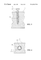
- FIG. 2 is a perspective view of the present invention
- FIGS. 3 and 4 illustrate the working principle of the present invention.
- the screw 2 comprises a shank (shown but not numbered) formed with spiral circular threads 21 at the upper portion and spiral triangular threads 22 at the lower portion.
- Each of the spiral triangular threads 22 has three sharp edges and three pointed tips 221 .
- the spiral triangular threads 22 are arranged so that the pointed tips 221 of each of the spiral triangular threads 22 are located at different positions. However, the pointed tips 221 of the spiral triangular threads 22 may be arranged in alignment as required. As the screw 2 is turned into a piece of wood, the pointed tips 221 of the triangular threads 22 of the screw 2 will cut the wood before the circular threads 21 are turned into the wood thereby making it easier for the screw 2 to turn into the wood.
- the pointed tips 221 of the triangular threads will cut the wood 3 when turned into the wood thereby facilitating the screw 2 to turn into the wood 3 . Further, a spiral passage will be formed as soon as the pointed tips 221 of the triangular threads 22 are turned into the wood 3 so that the circular threads 21 can be easily turned into the wood 3 along the spiral passage.
- threads 22 may be of other shapes such as pentagon, hexagon, or the like and each of the elements described above, or two or more together may also find a useful application in other types of methods differing from the type described above.
Landscapes
- Engineering & Computer Science (AREA)
- General Engineering & Computer Science (AREA)
- Mechanical Engineering (AREA)
- Physics & Mathematics (AREA)
- Geometry (AREA)
- Life Sciences & Earth Sciences (AREA)
- Chemical & Material Sciences (AREA)
- Dispersion Chemistry (AREA)
- Wood Science & Technology (AREA)
- Joining Of Building Structures In Genera (AREA)
- Connection Of Plates (AREA)
Abstract
A screw comprising a shank having an upper portion formed with spiral circular threads and a lower portion formed with spiral triangular threads, each of said spiral triangular threads having three sharp edges and three pointed tips, said pointed tips of said spiral triangular threads being located at different positions, whereby the screw can be easily and rapidly turned into a piece of hard wood.
Description
1. Field of the Invention
This invention is related to an improvement in the structure of a screw and in particular to one which can be easily turned into a piece hard wood.
2. Description of the Prior Art
The conventional screw consists essentially of a solid cylinder, usually of metal, around which a thread winds spirally, either clockwise or counterclockwise. However, it is difficult to turn the screw into an object if it is made of hard wood. Hence, an improved screw (see FIG. 1) has been designed to obviate this drawback. As shown, the screw includes a shank 1 formed with spiral circular threads 11 at the upper portion thereof. The spiral circular threads 11 at the lower portion of the shank 1 are provided with a plurality of teeth 12 for facilitating the tuning of the screw into the wood. Nevertheless, although the teeth 12 enables the screw to turn into a piece of hard wood, it still requires a lot of effort to turn the screw thereby often making one feel utterly exhausted in order to fasten pieces of hard wood.
Therefore, it is an object of the present invention to provide an improvement in the structure of a screw which can obviate and mitigate the above-mentioned drawbacks.
This invention is related to an improvement in the structure of a screw.
According to a preferred embodiment of the present invention, a screw comprising a shank having an upper portion formed with spiral circular threads and a lower portion formed with spiral triangular threads, each of said spiral triangular threads having three sharp edges and three pointed tips, said pointed tips of said spiral triangular threads being located at different positions.
It is the primary object of the present invention to provide an improved screw which can be easily turned into a piece of hard wood.
It is another object of the present invention to provide an improved screw which is simple in construction.
It is a further object of the present invention to provide an improved screw which is inexpensive to manufacture.
The foregoing objects and summary provide only a brief introduction to the present invention. To filly appreciate these and other objects of the present invention as well as the invention itself, all of which will become apparent to those skilled in the art, the following detailed description of the invention and the claims should be read in conjunction with the accompanying drawings. Throughout the specification and drawings identical reference numerals refer to identical or similar parts. Many other advantages and features of the present invention will become manifest to those versed in the art upon making reference to the detailed description and the accompanying sheets of drawings in which a preferred structural embodiment incorporating the principles of the present invention is shown by way of illustrative example.
FIG. 1 is a perspective view of a prior art screw;
FIG. 2 is a perspective view of the present invention;
FIGS. 3 and 4 illustrate the working principle of the present invention.
For the purpose of promoting an understanding of the principles of the invention, reference will now be made to the embodiment illustrated in the drawings. Specific language will be used to describe same. It will, nevertheless, be understood that no limitation of the scope of the invention is thereby intended, such alterations and further modifications in the illustrated device, and such further applications of the principles of the invention as illustrated herein being contemplated as would normally occur to one skilled in the art to which the invention relates.
With reference to the drawings and in particular to FIG. 2 thereof, the screw 2 according to the present invention comprises a shank (shown but not numbered) formed with spiral circular threads 21 at the upper portion and spiral triangular threads 22 at the lower portion. Each of the spiral triangular threads 22 has three sharp edges and three pointed tips 221. The spiral triangular threads 22 are arranged so that the pointed tips 221 of each of the spiral triangular threads 22 are located at different positions. However, the pointed tips 221 of the spiral triangular threads 22 may be arranged in alignment as required. As the screw 2 is turned into a piece of wood, the pointed tips 221 of the triangular threads 22 of the screw 2 will cut the wood before the circular threads 21 are turned into the wood thereby making it easier for the screw 2 to turn into the wood.
Referring to FIG. 3, the pointed tips 221 of the triangular threads will cut the wood 3 when turned into the wood thereby facilitating the screw 2 to turn into the wood 3. Further, a spiral passage will be formed as soon as the pointed tips 221 of the triangular threads 22 are turned into the wood 3 so that the circular threads 21 can be easily turned into the wood 3 along the spiral passage.
Looking now at FIG. 4, when the screw 2 is turned into the wood 3, the pointed tips 221 of the triangular threads 22 will cut the wood 3 but the three sides of the triangular threads 22 will not be in contact with the wood 3 thus reducing the friction between the screw 2 and the wood 3.
It will be understood that the threads 22 may be of other shapes such as pentagon, hexagon, or the like and each of the elements described above, or two or more together may also find a useful application in other types of methods differing from the type described above.
While certain novel features of this invention have been shown and described and are pointed out in the annexed claim, it is not intended to be limited to the details above, since it will be understood that various omissions, modifications, substitutions and changes in the forms and details of the device illustrated and in its operation can be made by those skilled in the art without departing in any way from the spirit of the present invention.
Claims (1)
1. A screw comprising a cylindrical shank having an upper portion formed with spiral circular threads and a lower portion formed with spiral triangular threads, each of said spiral triangular threads having three sharp edges and three pointed tips, the pointed tips of axially adjacent spiral triangular threads being located at circumferentially different positions, said cylindrical shank having a pointed end at a lower portion thereof.
Priority Applications (2)
| Application Number | Priority Date | Filing Date | Title |
|---|---|---|---|
| US09/451,712 US6254327B1 (en) | 1999-12-01 | 1999-12-01 | Screw with spiral triangular threads |
| US09/760,838 US6468014B2 (en) | 1999-12-01 | 2001-01-17 | Screw with spiral triangular threads |
Applications Claiming Priority (1)
| Application Number | Priority Date | Filing Date | Title |
|---|---|---|---|
| US09/451,712 US6254327B1 (en) | 1999-12-01 | 1999-12-01 | Screw with spiral triangular threads |
Related Child Applications (1)
| Application Number | Title | Priority Date | Filing Date |
|---|---|---|---|
| US09/760,838 Continuation-In-Part US6468014B2 (en) | 1999-12-01 | 2001-01-17 | Screw with spiral triangular threads |
Publications (1)
| Publication Number | Publication Date |
|---|---|
| US6254327B1 true US6254327B1 (en) | 2001-07-03 |
Family
ID=23793406
Family Applications (1)
| Application Number | Title | Priority Date | Filing Date |
|---|---|---|---|
| US09/451,712 Expired - Fee Related US6254327B1 (en) | 1999-12-01 | 1999-12-01 | Screw with spiral triangular threads |
Country Status (1)
| Country | Link |
|---|---|
| US (1) | US6254327B1 (en) |
Cited By (32)
| Publication number | Priority date | Publication date | Assignee | Title |
|---|---|---|---|---|
| US6450748B1 (en) * | 2000-05-30 | 2002-09-17 | Tai-Ping Hsu | Screw having a screw thread formed with concave facets |
| US20040079133A1 (en) * | 2001-06-19 | 2004-04-29 | Levey Kenneth | Method for making a fastener |
| US20040101381A1 (en) * | 2001-07-31 | 2004-05-27 | Illinois Tool Works Inc. | Threaded fastener for use within multiple substrates |
| US20040120791A1 (en) * | 2002-12-18 | 2004-06-24 | Panasik Cheryl L. | Threaded fastener with dual reinforcing leads and improved substrate entry or lead end portion |
| US20040228705A1 (en) * | 2003-05-16 | 2004-11-18 | Abbott-Interfast Corporation. | Fasteners for composite material |
| US20050126244A1 (en) * | 2002-12-18 | 2005-06-16 | Illinois Tool Works Inc. | Threaded fastener with dual reinforcing leads for facilitating manufacture of the fastener, thread rolling die for forming the threaded fastener, and method of manufacturing the threaded fastener |
| US20050158149A1 (en) * | 2001-06-19 | 2005-07-21 | Panasik Cheryl L. | Threaded fastener with dual reinforcing leads having arrowhead cross-sectional configuration and improved substrate entry or lead end portion, thread rolling die for forming the threaded fastener, and method for manufacturing the threaded fastener |
| US20050186048A1 (en) * | 2004-02-25 | 2005-08-25 | Robert Dicke | Thread-forming screw fastener |
| US20060147295A1 (en) * | 2005-01-05 | 2006-07-06 | Pei-Hua Chen | Screw with two types of threads |
| US7101134B2 (en) | 2001-06-19 | 2006-09-05 | Illinois Tool Works Inc. | Fastener having multiple lobed thread |
| US20070172333A1 (en) * | 2006-01-09 | 2007-07-26 | Tian-Fu Tsau | Screw member having two different thread angles formed on a sharp-edged thread |
| EP1939465A4 (en) * | 2005-09-28 | 2008-11-19 | Aironware Shangai Co Ltd | Self-tapping screw |
| EP2006552A1 (en) * | 2007-06-21 | 2008-12-24 | Easylink Industrial Co., Ltd. | Screw |
| US20090269164A1 (en) * | 2008-04-28 | 2009-10-29 | Illinois Tool Works Inc. | Fastener for stucco or hard board substrates |
| USD604153S1 (en) * | 2008-10-07 | 2009-11-17 | Wantz John B | Fastener |
| US20120063865A1 (en) * | 2010-09-14 | 2012-03-15 | Sheh Fung Screws Co., Ltd. | Screw |
| US20120251268A1 (en) * | 2011-03-28 | 2012-10-04 | Yu su-lan | Screw |
| USD678756S1 (en) * | 2010-12-30 | 2013-03-26 | A-Stainless International Co., Ltd. | Screw |
| US20160367304A1 (en) * | 2013-06-27 | 2016-12-22 | Aesculap Ag | Out-of-round pedicle screw |
| US20200208670A1 (en) * | 2018-12-31 | 2020-07-02 | Robert E. Stewart | Faceted lobular threads |
| USD898196S1 (en) | 2017-07-10 | 2020-10-06 | Stryker European Holdings I, Llc | Spinal fastener with serrated thread |
| US20200324893A1 (en) * | 2019-04-11 | 2020-10-15 | Bell Helicopter Textron Inc. | Aircraft coupling mechanism |
| US11199214B2 (en) * | 2019-09-20 | 2021-12-14 | Essence Method Refine Co., Ltd. | Quick fastening screw |
| US11204055B2 (en) * | 2017-08-31 | 2021-12-21 | The Hillman Group, Inc. | Sheet metal screw |
| US20220056941A1 (en) * | 2020-06-04 | 2022-02-24 | Process Displays Llc | Threaded fastener and connector |
| US11389205B2 (en) | 2016-11-30 | 2022-07-19 | Stryker European Operations Holdings Llc | Spinal fastener with serrated thread |
| USD1075491S1 (en) * | 2023-08-09 | 2025-05-20 | Integral Building Products Incorporation | Screw |
| US12473942B2 (en) | 2021-03-30 | 2025-11-18 | The Hillman Group, Inc. | Wood screw |
| USD1106810S1 (en) | 2022-09-29 | 2025-12-23 | The Hillman Group, Inc. | Screw |
| USD1115507S1 (en) | 2023-06-02 | 2026-03-03 | The Hillman Group, Inc. | Screw |
| USD1116789S1 (en) | 2023-06-02 | 2026-03-10 | The Hillman Group, Inc. | Screw |
| USD1116658S1 (en) * | 2020-11-26 | 2026-03-10 | Illinois Tool Works Inc. | Fastener |
Citations (6)
| Publication number | Priority date | Publication date | Assignee | Title |
|---|---|---|---|---|
| GB957675A (en) * | 1959-06-09 | 1964-05-13 | Res Eng & Mfg | Self-tapping screws |
| US3918345A (en) * | 1961-06-27 | 1975-11-11 | Res Eng & Mfg | Thread forming fasteners |
| GB2040769A (en) * | 1979-01-16 | 1980-09-03 | Tdk Electronics Co Ltd | Self-tapping screw |
| US4637767A (en) * | 1980-12-26 | 1987-01-20 | Topura Co., Ltd. | Threaded fastener |
| US5044855A (en) * | 1990-08-31 | 1991-09-03 | Nitto Seiko Co., Ltd. | Thread-forming fasteners |
| US5772374A (en) * | 1996-01-08 | 1998-06-30 | Aoyama Seisakusho Co., Ltd. | Tapping screw and mechanism of engaging member to be engaged using the same |
-
1999
- 1999-12-01 US US09/451,712 patent/US6254327B1/en not_active Expired - Fee Related
Patent Citations (6)
| Publication number | Priority date | Publication date | Assignee | Title |
|---|---|---|---|---|
| GB957675A (en) * | 1959-06-09 | 1964-05-13 | Res Eng & Mfg | Self-tapping screws |
| US3918345A (en) * | 1961-06-27 | 1975-11-11 | Res Eng & Mfg | Thread forming fasteners |
| GB2040769A (en) * | 1979-01-16 | 1980-09-03 | Tdk Electronics Co Ltd | Self-tapping screw |
| US4637767A (en) * | 1980-12-26 | 1987-01-20 | Topura Co., Ltd. | Threaded fastener |
| US5044855A (en) * | 1990-08-31 | 1991-09-03 | Nitto Seiko Co., Ltd. | Thread-forming fasteners |
| US5772374A (en) * | 1996-01-08 | 1998-06-30 | Aoyama Seisakusho Co., Ltd. | Tapping screw and mechanism of engaging member to be engaged using the same |
Cited By (51)
| Publication number | Priority date | Publication date | Assignee | Title |
|---|---|---|---|---|
| US6450748B1 (en) * | 2000-05-30 | 2002-09-17 | Tai-Ping Hsu | Screw having a screw thread formed with concave facets |
| US20040079133A1 (en) * | 2001-06-19 | 2004-04-29 | Levey Kenneth | Method for making a fastener |
| US7156600B2 (en) | 2001-06-19 | 2007-01-02 | Illinois Tool Works Inc. | Die for, method of making, and fastener with lobed primary thread lead and interposed dual auxiliary thread lead with improved substrate entry end portion |
| US6899500B2 (en) | 2001-06-19 | 2005-05-31 | Illinois Tool Works Inc. | Fastner having multiple-bossed lead |
| US7101134B2 (en) | 2001-06-19 | 2006-09-05 | Illinois Tool Works Inc. | Fastener having multiple lobed thread |
| US6956181B2 (en) | 2001-06-19 | 2005-10-18 | Illinois Tool Works, Inc. | Method for making a fastener |
| US20050158149A1 (en) * | 2001-06-19 | 2005-07-21 | Panasik Cheryl L. | Threaded fastener with dual reinforcing leads having arrowhead cross-sectional configuration and improved substrate entry or lead end portion, thread rolling die for forming the threaded fastener, and method for manufacturing the threaded fastener |
| US6926484B2 (en) | 2001-07-31 | 2005-08-09 | Illinois Tool Works Inc. | Threaded fastener for use within multiple substrates |
| US20040101381A1 (en) * | 2001-07-31 | 2004-05-27 | Illinois Tool Works Inc. | Threaded fastener for use within multiple substrates |
| US6957557B2 (en) | 2002-12-18 | 2005-10-25 | Illinois Tool Works Inc. | Threaded fastener with dual reinforcing leads for facilitating manufacture of the fastener, thread rolling die for forming the threaded fastener, and method of manufacturing the threaded fastener |
| US7458759B2 (en) | 2002-12-18 | 2008-12-02 | Illinois Tool Works Inc. | Threaded fastener with dual reinforcing leads for facilitating manufacture of the fastener, thread rolling die for forming the threaded fastener, and method of manufacturing the threaded fastener |
| US20050135900A1 (en) * | 2002-12-18 | 2005-06-23 | Illinois Tool Works Inc. | Threaded fastener with dual reinforcing leads for facilitating manufacture of the fastener, thread rolling die for forming the threaded fastener, and method of manufacturing the threaded fastener |
| US20040120791A1 (en) * | 2002-12-18 | 2004-06-24 | Panasik Cheryl L. | Threaded fastener with dual reinforcing leads and improved substrate entry or lead end portion |
| US7076989B2 (en) | 2002-12-18 | 2006-07-18 | Illinois Tool Works Inc. | Threaded fastener with dual reinforcing leads for facilitating manufacture of the fastener, thread rolling die for forming the threaded fastener, and method of manufacturing the threaded fastener |
| US20050126244A1 (en) * | 2002-12-18 | 2005-06-16 | Illinois Tool Works Inc. | Threaded fastener with dual reinforcing leads for facilitating manufacture of the fastener, thread rolling die for forming the threaded fastener, and method of manufacturing the threaded fastener |
| US8430618B2 (en) | 2003-05-16 | 2013-04-30 | Abbott-Interfast Corporation | Fasteners for composite material |
| US20040228705A1 (en) * | 2003-05-16 | 2004-11-18 | Abbott-Interfast Corporation. | Fasteners for composite material |
| US7101133B2 (en) * | 2004-02-25 | 2006-09-05 | A-Z Ausrustung Und Zubehor Gmbh & Co Kg | Thread-forming screw fastener |
| US20050186048A1 (en) * | 2004-02-25 | 2005-08-25 | Robert Dicke | Thread-forming screw fastener |
| US7163366B2 (en) * | 2005-01-05 | 2007-01-16 | Pei-Hua Chen | Screw with two types of threads |
| US20060147295A1 (en) * | 2005-01-05 | 2006-07-06 | Pei-Hua Chen | Screw with two types of threads |
| EP1939465A4 (en) * | 2005-09-28 | 2008-11-19 | Aironware Shangai Co Ltd | Self-tapping screw |
| US20070172333A1 (en) * | 2006-01-09 | 2007-07-26 | Tian-Fu Tsau | Screw member having two different thread angles formed on a sharp-edged thread |
| EP2006552A1 (en) * | 2007-06-21 | 2008-12-24 | Easylink Industrial Co., Ltd. | Screw |
| US20090269164A1 (en) * | 2008-04-28 | 2009-10-29 | Illinois Tool Works Inc. | Fastener for stucco or hard board substrates |
| US8511957B2 (en) | 2008-04-28 | 2013-08-20 | Illinoks Tool Works Inc. | Fastener for stucco or hard board substrates |
| USD604153S1 (en) * | 2008-10-07 | 2009-11-17 | Wantz John B | Fastener |
| US20120063865A1 (en) * | 2010-09-14 | 2012-03-15 | Sheh Fung Screws Co., Ltd. | Screw |
| USD678756S1 (en) * | 2010-12-30 | 2013-03-26 | A-Stainless International Co., Ltd. | Screw |
| US8360702B2 (en) * | 2011-03-28 | 2013-01-29 | Yu su-lan | Screw |
| US20120251268A1 (en) * | 2011-03-28 | 2012-10-04 | Yu su-lan | Screw |
| US20160367304A1 (en) * | 2013-06-27 | 2016-12-22 | Aesculap Ag | Out-of-round pedicle screw |
| US10413343B2 (en) * | 2013-06-27 | 2019-09-17 | Aesculap Ag | Out-of-round pedicle screw |
| US12167871B2 (en) | 2016-11-30 | 2024-12-17 | Stryker European Operations Holdings Llc | Spinal fastener with serrated thread |
| US11389205B2 (en) | 2016-11-30 | 2022-07-19 | Stryker European Operations Holdings Llc | Spinal fastener with serrated thread |
| USD898196S1 (en) | 2017-07-10 | 2020-10-06 | Stryker European Holdings I, Llc | Spinal fastener with serrated thread |
| USD926983S1 (en) | 2017-07-10 | 2021-08-03 | Stryker European Holdings I, Llc | Spinal fastener with serrated thread |
| USD951454S1 (en) | 2017-07-10 | 2022-05-10 | Stryker European Operations Holdings Llc | Spinal fastener with serrated thread |
| US11204055B2 (en) * | 2017-08-31 | 2021-12-21 | The Hillman Group, Inc. | Sheet metal screw |
| US20200208670A1 (en) * | 2018-12-31 | 2020-07-02 | Robert E. Stewart | Faceted lobular threads |
| US11686337B2 (en) * | 2018-12-31 | 2023-06-27 | Robert E. Stewart | Faceted lobular threads |
| US20200324893A1 (en) * | 2019-04-11 | 2020-10-15 | Bell Helicopter Textron Inc. | Aircraft coupling mechanism |
| US11724804B2 (en) * | 2019-04-11 | 2023-08-15 | Textron Innovations Inc. | Aircraft coupling mechanism |
| US11199214B2 (en) * | 2019-09-20 | 2021-12-14 | Essence Method Refine Co., Ltd. | Quick fastening screw |
| US20220056941A1 (en) * | 2020-06-04 | 2022-02-24 | Process Displays Llc | Threaded fastener and connector |
| USD1116658S1 (en) * | 2020-11-26 | 2026-03-10 | Illinois Tool Works Inc. | Fastener |
| US12473942B2 (en) | 2021-03-30 | 2025-11-18 | The Hillman Group, Inc. | Wood screw |
| USD1106810S1 (en) | 2022-09-29 | 2025-12-23 | The Hillman Group, Inc. | Screw |
| USD1115507S1 (en) | 2023-06-02 | 2026-03-03 | The Hillman Group, Inc. | Screw |
| USD1116789S1 (en) | 2023-06-02 | 2026-03-10 | The Hillman Group, Inc. | Screw |
| USD1075491S1 (en) * | 2023-08-09 | 2025-05-20 | Integral Building Products Incorporation | Screw |
Similar Documents
| Publication | Publication Date | Title |
|---|---|---|
| US6254327B1 (en) | Screw with spiral triangular threads | |
| US6468014B2 (en) | Screw with spiral triangular threads | |
| CA2234092C (en) | Self perforating and thread forming connecting element | |
| US7677854B2 (en) | Self-boring and self-tapping screw | |
| US6227783B1 (en) | Fastener with retaining sleeve | |
| US11125262B2 (en) | Thread forming and thread locking fastener | |
| CA2336934A1 (en) | Osteosynthesis screw, especially for application by a translaminar vertebral screw | |
| US6402448B1 (en) | Self-drilling and self-tapping screw | |
| US327296A (en) | William t | |
| ATE233376T1 (en) | SCREW, ESPECIALLY CONCRETE SCREW | |
| US6273656B1 (en) | Push pin fastener | |
| CA2140297A1 (en) | Low torque wood screw | |
| US2895362A (en) | Wrench | |
| US5863165A (en) | Self-tapping screw | |
| US5158409A (en) | Bolt lock device | |
| US2886087A (en) | Lock nut having a conically tapered reduced end portion | |
| US5294224A (en) | C-shaped fastening clip with improved strength | |
| US2164382A (en) | Nut | |
| US3093178A (en) | Retainer fastener | |
| CA2497932A1 (en) | Threaded fastener assembly | |
| JPS5859517U (en) | face milling | |
| JPS58178007A (en) | Light nut | |
| CA2048964C (en) | Set screw | |
| JPH10169628A (en) | Nut detent device | |
| JPH10281130A (en) | Deformed bar formed integrally with male screw part with head |
Legal Events
| Date | Code | Title | Description |
|---|---|---|---|
| AS | Assignment |
Owner name: CHUN-CHIN SCREW CO., LTD., TAIWAN Free format text: ASSIGNMENT OF ASSIGNORS INTEREST;ASSIGNOR:CHEN, CHUN-CHIN;REEL/FRAME:010423/0698 Effective date: 19991020 |
|
| REMI | Maintenance fee reminder mailed | ||
| REMI | Maintenance fee reminder mailed | ||
| LAPS | Lapse for failure to pay maintenance fees | ||
| STCH | Information on status: patent discontinuation |
Free format text: PATENT EXPIRED DUE TO NONPAYMENT OF MAINTENANCE FEES UNDER 37 CFR 1.362 |
|
| FP | Lapsed due to failure to pay maintenance fee |
Effective date: 20050703 |