US623807A - Bicycle-support - Google Patents
Bicycle-support Download PDFInfo
- Publication number
- US623807A US623807A US623807DA US623807A US 623807 A US623807 A US 623807A US 623807D A US623807D A US 623807DA US 623807 A US623807 A US 623807A
- Authority
- US
- United States
- Prior art keywords
- support
- bicycle
- wheel
- spring
- casing
- Prior art date
- Legal status (The legal status is an assumption and is not a legal conclusion. Google has not performed a legal analysis and makes no representation as to the accuracy of the status listed.)
- Expired - Lifetime
Links
- 210000003414 Extremities Anatomy 0.000 description 6
- 210000003811 Fingers Anatomy 0.000 description 4
- 206010022114 Injury Diseases 0.000 description 2
- 210000003141 Lower Extremity Anatomy 0.000 description 2
- 238000010276 construction Methods 0.000 description 2
- 230000000875 corresponding Effects 0.000 description 2
- 230000005484 gravity Effects 0.000 description 2
- 230000000284 resting Effects 0.000 description 2
Images
Classifications
-
- B—PERFORMING OPERATIONS; TRANSPORTING
- B62—LAND VEHICLES FOR TRAVELLING OTHERWISE THAN ON RAILS
- B62H—CYCLE STANDS; SUPPORTS OR HOLDERS FOR PARKING OR STORING CYCLES; APPLIANCES PREVENTING OR INDICATING UNAUTHORIZED USE OR THEFT OF CYCLES; LOCKS INTEGRAL WITH CYCLES; DEVICES FOR LEARNING TO RIDE CYCLES
- B62H3/00—Separate supports or holders for parking or storing cycles
- B62H3/08—Separate supports or holders for parking or storing cycles involving recesses or channelled rails for embracing the bottom part of a wheel
Definitions
- THE onlus PETERS co.. PHOTO-urna., wAsmNcrcN. D. c.
- My invention consists of a bicyclesupport which when notin use is practically invisible and adapted to automatically descend into a suitable casing, whereby space is economized and there is,furthermore, no liability of accident or damage happeningr to the support by being struck from above or presenting an obstacle on the sidewalks, road, ttc., the bicycle-wheel being adapted to be held on said casing by a yielding pressure without injury to the tire thereof, and provision is made for adjusting said pressure.
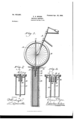
- Figure l represents a side elevation of a bicycle-support embodying myinvention and a portion of a wheel to which the same is applicable, the casing for said support being shown in section.
- Fig. 2 represents, on an enlarged scale,a side elevation of the support, showing the upper portion of the casin g therefor and the position the parts normally assume when the support is not in use.
- Fig. 3 represents a section on line x no, Fig. 2.
- A designates the fork of a bicycle
- B designates the wheel thereof, the latter being shown in Fig. l as engaged by the clip or support C, which consists of a loop or U-shaped member D, the same passing through perforations or openings E in the block or cap F, which is supported on the top of the casing H.
- .l designates a seat in the upper portion of the plate G, the same being of sufficient depth so that the crown of the member D will be either liush with or just below the surface of the plate G when said member is in its lowest or inoperative position.
- K designates side recesses in the upper portion of the plate Gr, the same being located so as to enable the fingers of the user or operator to readily grasp the upper portion of the support C, and so raise the same from the position seen in Figs. 2 and?) to position seen in Fig. l when it is desired to use the device.
- L designates a nut or stop attached to the lower portion of one or both of the members D, said nuthaving one extremity of the spring M abutting thereagainst, while the other eX- tremity of said spring makes contact with the lower portion of the body F when the support is in its uppermost or operative position, as indicated in Fig. l.
- the tension of the springM may be adjusted so as to cause the crown of the member C to eXert more or less pressure on the bicycle-wheel for properly holding the latter on the cap G.
- a bicycle-support consisting of a casing adapted to be concealed in the ground, a perforated cap thereon, a loop-shaped member adapted to slide through said cap, a stop on the lower end of said member, a spring on said member, one end of said spring abutting against said eap when said member is in raised position, While the other extremity of said spring is adapted to Contact with saidv stop, whereby the erown of said member is adapted to exert adownward yielding pressure on the wheel of a bicycle resting on said eap.
- casing having a plate secured in the upperv portion thereof, said plate having a body portion provided with openings therein, a seat in the upper portion of said plate, recesses in thelatter, a support consisting of a U-shaped member, thelimbs of which latter are movably mounted in said openings, a stop on the lower extremity of one of said limbs, and a spring supported upon said stop, said spring being adapted to pull downwardly upon said support, when the latter is in operative position, wherebysaid support is adapted to firmly engage and sustain a bicycle-wheel.
- WIEDERSHEIM JOHN A. WIEDERSHEIM, WM. C. WIEDERSHEIM.
Description
No.' 623,807. ,Patented Apr. 25, |899.
c. A. MYERS. BICYCLE SUPPORT.
(Application led May 6? 189B.)
(No Model.)
HI IUKNhYS.
WITNESSES:
THE onlus PETERS co.. PHOTO-urna., wAsmNcrcN. D. c.
@with Sterns Armar n Crrics.
CLARENCE A. MYERS, CF ATLANTIC CITY, NEX/V JERSEY.
BICYCLE-SUPPORT.
SPECIFICATION forming part of Letters Patent No. 623,807, dated April 25, 1899.
Application filed May 6,1898. Serial N o. 679,890. (No model.)
To all whom, t 77u63/ concern:
lle itknown that I, CLARENCE A. MYERS, a citizen of the United States, residing at Atlantic City, in the county ot' Atlantic, State ot New Jersey, have invented a new and useful Improvement in Bicycle-Supports, which improvement is fully set forth in the following specification and accompanying drawings.
My invention consists of a bicyclesupport which when notin use is practically invisible and adapted to automatically descend into a suitable casing, whereby space is economized and there is,furthermore, no liability of accident or damage happeningr to the support by being struck from above or presenting an obstacle on the sidewalks, road, ttc., the bicycle-wheel being adapted to be held on said casing by a yielding pressure without injury to the tire thereof, and provision is made for adjusting said pressure.
It further consists of novel details of construction, all as will be hereinafter fully set forth, and particularly pointed out in the claims. A
Figure l represents a side elevation of a bicycle-support embodying myinvention and a portion of a wheel to which the same is applicable, the casing for said support being shown in section. Fig. 2 represents, on an enlarged scale,a side elevation of the support, showing the upper portion of the casin g therefor and the position the parts normally assume when the support is not in use. Fig. 3 represents a section on line x no, Fig. 2.
Similar letters of reference indicate corresponding parts in the figures.
Referring to the drawings, A designates the fork of a bicycle, and B designates the wheel thereof, the latter being shown in Fig. l as engaged by the clip or support C, which consists of a loop or U-shaped member D, the same passing through perforations or openings E in the block or cap F, which is supported on the top of the casing H.
.l designates a seat in the upper portion of the plate G, the same being of sufficient depth so that the crown of the member D will be either liush with or just below the surface of the plate G when said member is in its lowest or inoperative position.
K designates side recesses in the upper portion of the plate Gr, the same being located so as to enable the fingers of the user or operator to readily grasp the upper portion of the support C, and so raise the same from the position seen in Figs. 2 and?) to position seen in Fig. l when it is desired to use the device.
L designates a nut or stop attached to the lower portion of one or both of the members D, said nuthaving one extremity of the spring M abutting thereagainst, while the other eX- tremity of said spring makes contact with the lower portion of the body F when the support is in its uppermost or operative position, as indicated in Fig. l.
The operation is as follows: The parts normally appear as seen in Figs. 2 and 3, the member I) of the support being in the main contained or concealed within the casing H, which latter is sunk into the ground. When it is desired to use the support, the operator inserts his fin gers in the recesses K and draws the support upwardly into the position seen in Fig. l, whereupon the bicycle-wheel can be pushed into the space between the members D, the top or crown of the support C being caused to rmly engage the contiguous portion of the tire of the wheel by reason of the pressure of the spring` M, it being of course apparent that when the parts are in the position seen in Fig. l said spring M tends to exert a downward pull upon the support C, thus holding the wheel in uprightl position as long as may be desired. XV hen the wheel is withdrawn from the support C, the latter falls by gravity into the position seen in Figs. 2 and 3, as will be evident, said support then being mainly invisible and removed from the liability of being struck or obstructing the sidewalk, road, dac. Owing to the nut L, the tension of the springM may be adjusted so as to cause the crown of the member C to eXert more or less pressure on the bicycle-wheel for properly holding the latter on the cap G.
Having thus described my invention, what I claim as new, and desire to secure byLetters Patent, is
l. A bicycle-support consisting of a casing adapted to be concealed in the ground, a perforated cap thereon, a loop-shaped member adapted to slide through said cap, a stop on the lower end of said member, a spring on said member, one end of said spring abutting against said eap when said member is in raised position, While the other extremity of said spring is adapted to Contact with saidv stop, whereby the erown of said member is adapted to exert adownward yielding pressure on the wheel of a bicycle resting on said eap.
2. In a device of the character named, a
casing having a plate secured in the upperv portion thereof, said plate having a body portion provided with openings therein, a seat in the upper portion of said plate, recesses in thelatter, a support consisting of a U-shaped member, thelimbs of which latter are movably mounted in said openings, a stop on the lower extremity of one of said limbs, and a spring supported upon said stop, said spring being adapted to pull downwardly upon said support, when the latter is in operative position, wherebysaid support is adapted to firmly engage and sustain a bicycle-wheel.
CLARENCE A. MYERS.
Witnesses:
JOHN A. WIEDERSHEIM, WM. C. WIEDERSHEIM.
Publications (1)
| Publication Number | Publication Date |
|---|---|
| US623807A true US623807A (en) | 1899-04-25 |
Family
ID=2692412
Family Applications (1)
| Application Number | Title | Priority Date | Filing Date |
|---|---|---|---|
| US623807D Expired - Lifetime US623807A (en) | Bicycle-support |
Country Status (1)
| Country | Link |
|---|---|
| US (1) | US623807A (en) |
Cited By (12)
| Publication number | Priority date | Publication date | Assignee | Title |
|---|---|---|---|---|
| US5692659A (en) * | 1994-02-22 | 1997-12-02 | Sportworks Northwest, Inc. | Bicycle rack |
| US20030209582A1 (en) * | 1995-03-16 | 2003-11-13 | Reeves Michael K. | Bicycle rack |
| US6761297B1 (en) | 2001-08-23 | 2004-07-13 | Fabio Pedrini | Ride ready vehicle-mounted bicycle carrier |
| US7044347B1 (en) | 2003-03-06 | 2006-05-16 | Fabio Pedrini | Interlock arrangement for an extendible and retractable stabilizer for use in a bicycle carrier |
| US20060273126A1 (en) * | 2005-05-31 | 2006-12-07 | Fabio Pedrini | Bicycle Support With Pivoting Wheel Engagement Member |
| US7150359B1 (en) * | 2004-02-24 | 2006-12-19 | Charles Michael Lyons | Motorcycle wheel stand for parking and transport |
| US9187047B2 (en) | 2012-04-30 | 2015-11-17 | Yakima Products, Inc. | Retention dock |
| US9393912B2 (en) | 2011-09-08 | 2016-07-19 | Fabio Pedrini | Bicycle-carrier device for motor vehicles |
| USD779386S1 (en) | 2015-06-08 | 2017-02-21 | Yakima Products, Inc. | Hub for bicycle rack |
| USD780641S1 (en) | 2015-06-08 | 2017-03-07 | Yakima Products, Inc. | Frame for bicycle rack |
| US9649986B2 (en) | 2013-09-17 | 2017-05-16 | Fabio Pedrini | Wheel clamping bicycle carrier |
| US9815415B2 (en) | 2015-06-05 | 2017-11-14 | Yakima Products, Inc. | Adjustable bicycle carrier |
-
0
- US US623807D patent/US623807A/en not_active Expired - Lifetime
Cited By (16)
| Publication number | Priority date | Publication date | Assignee | Title |
|---|---|---|---|---|
| US5692659A (en) * | 1994-02-22 | 1997-12-02 | Sportworks Northwest, Inc. | Bicycle rack |
| US20030209582A1 (en) * | 1995-03-16 | 2003-11-13 | Reeves Michael K. | Bicycle rack |
| US7104430B2 (en) | 1995-03-16 | 2006-09-12 | Sportworks Northwest, Inc. | Bicycle rack |
| US7222763B2 (en) | 2001-08-23 | 2007-05-29 | Fabio Pedrini | Pivoting support arrangement for maintaining a bicycle wheel in an upright position |
| US6761297B1 (en) | 2001-08-23 | 2004-07-13 | Fabio Pedrini | Ride ready vehicle-mounted bicycle carrier |
| US20040238582A1 (en) * | 2001-08-23 | 2004-12-02 | Fabio Pedrini | Pivoting support arrangement for maintaining a bicycle wheel in an upright position |
| US7044347B1 (en) | 2003-03-06 | 2006-05-16 | Fabio Pedrini | Interlock arrangement for an extendible and retractable stabilizer for use in a bicycle carrier |
| US7150359B1 (en) * | 2004-02-24 | 2006-12-19 | Charles Michael Lyons | Motorcycle wheel stand for parking and transport |
| US20060273126A1 (en) * | 2005-05-31 | 2006-12-07 | Fabio Pedrini | Bicycle Support With Pivoting Wheel Engagement Member |
| US7648151B2 (en) | 2005-05-31 | 2010-01-19 | Fabio Pedrini | Bicycle support with pivoting wheel engagement member |
| US9393912B2 (en) | 2011-09-08 | 2016-07-19 | Fabio Pedrini | Bicycle-carrier device for motor vehicles |
| US9187047B2 (en) | 2012-04-30 | 2015-11-17 | Yakima Products, Inc. | Retention dock |
| US9649986B2 (en) | 2013-09-17 | 2017-05-16 | Fabio Pedrini | Wheel clamping bicycle carrier |
| US9815415B2 (en) | 2015-06-05 | 2017-11-14 | Yakima Products, Inc. | Adjustable bicycle carrier |
| USD779386S1 (en) | 2015-06-08 | 2017-02-21 | Yakima Products, Inc. | Hub for bicycle rack |
| USD780641S1 (en) | 2015-06-08 | 2017-03-07 | Yakima Products, Inc. | Frame for bicycle rack |
Similar Documents
| Publication | Publication Date | Title |
|---|---|---|
| US623807A (en) | Bicycle-support | |
| US621072A (en) | Bicycle holder and fastener | |
| US9434433B1 (en) | Safety motorcycle stand | |
| US948349A (en) | Bicycle and motor-cycle holder. | |
| US7267353B1 (en) | Motorcycle kickstand support | |
| US549145A (en) | Combined card-case | |
| US516571A (en) | Bicycle-stand | |
| US1087567A (en) | Hitching-post. | |
| US1216730A (en) | Grain-tank seat. | |
| US597510A (en) | Edward spejtcer piper | |
| US588291A (en) | Bicycle-stand | |
| US546612A (en) | Bicycle-support | |
| US966043A (en) | Vehicle-step. | |
| US1213938A (en) | Detachable handle for trucks. | |
| US1233300A (en) | Bicycle-support. | |
| US396182A (en) | Foot-rest for bicycles | |
| US1107427A (en) | Bicycle-support. | |
| US640880A (en) | Umbrella-holder. | |
| US1068964A (en) | Vehicle-support. | |
| US2468763A (en) | Bicycle stand | |
| US643936A (en) | Support and locking device for bicycles. | |
| US517824A (en) | Mole-trap | |
| US576071A (en) | Half to hobart b | |
| US601109A (en) | John j | |
| US1305589A (en) | Paper-file |