US6236919B1 - Method and apparatus providing operation of an integration hub for automotive signals during low voltage conditions - Google Patents
Method and apparatus providing operation of an integration hub for automotive signals during low voltage conditions Download PDFInfo
- Publication number
- US6236919B1 US6236919B1 US09/415,842 US41584299A US6236919B1 US 6236919 B1 US6236919 B1 US 6236919B1 US 41584299 A US41584299 A US 41584299A US 6236919 B1 US6236919 B1 US 6236919B1
- Authority
- US
- United States
- Prior art keywords
- automotive
- voltage
- signals
- measure
- automotive signals
- Prior art date
- Legal status (The legal status is an assumption and is not a legal conclusion. Google has not performed a legal analysis and makes no representation as to the accuracy of the status listed.)
- Expired - Lifetime
Links
- 230000010354 integration Effects 0.000 title claims abstract description 20
- 238000000034 method Methods 0.000 title claims description 24
- 238000012545 processing Methods 0.000 claims abstract description 6
- 230000006870 function Effects 0.000 claims description 35
- 230000000737 periodic effect Effects 0.000 claims description 3
- 238000012360 testing method Methods 0.000 claims description 3
- 230000008569 process Effects 0.000 description 12
- 239000004020 conductor Substances 0.000 description 5
- 230000008859 change Effects 0.000 description 3
- 230000000694 effects Effects 0.000 description 2
- 238000001914 filtration Methods 0.000 description 2
- 238000012986 modification Methods 0.000 description 2
- 230000004048 modification Effects 0.000 description 2
- 230000004913 activation Effects 0.000 description 1
- 238000001994 activation Methods 0.000 description 1
- 230000003466 anti-cipated effect Effects 0.000 description 1
- 238000013461 design Methods 0.000 description 1
- 238000011161 development Methods 0.000 description 1
- 238000010586 diagram Methods 0.000 description 1
- 238000007781 pre-processing Methods 0.000 description 1
- 238000011160 research Methods 0.000 description 1
- 239000007858 starting material Substances 0.000 description 1
Images


Classifications
-
- G—PHYSICS
- G05—CONTROLLING; REGULATING
- G05B—CONTROL OR REGULATING SYSTEMS IN GENERAL; FUNCTIONAL ELEMENTS OF SUCH SYSTEMS; MONITORING OR TESTING ARRANGEMENTS FOR SUCH SYSTEMS OR ELEMENTS
- G05B19/00—Programme-control systems
- G05B19/02—Programme-control systems electric
- G05B19/04—Programme control other than numerical control, i.e. in sequence controllers or logic controllers
- G05B19/042—Programme control other than numerical control, i.e. in sequence controllers or logic controllers using digital processors
- G05B19/0423—Input/output
- G05B19/0425—Safety, monitoring
-
- G—PHYSICS
- G05—CONTROLLING; REGULATING
- G05B—CONTROL OR REGULATING SYSTEMS IN GENERAL; FUNCTIONAL ELEMENTS OF SUCH SYSTEMS; MONITORING OR TESTING ARRANGEMENTS FOR SUCH SYSTEMS OR ELEMENTS
- G05B2219/00—Program-control systems
- G05B2219/20—Pc systems
- G05B2219/21—Pc I-O input output
- G05B2219/21107—Change sensivity of detection if input value is very low
-
- G—PHYSICS
- G05—CONTROLLING; REGULATING
- G05B—CONTROL OR REGULATING SYSTEMS IN GENERAL; FUNCTIONAL ELEMENTS OF SUCH SYSTEMS; MONITORING OR TESTING ARRANGEMENTS FOR SUCH SYSTEMS OR ELEMENTS
- G05B2219/00—Program-control systems
- G05B2219/20—Pc systems
- G05B2219/21—Pc I-O input output
- G05B2219/21141—Latched I-O
-
- G—PHYSICS
- G05—CONTROLLING; REGULATING
- G05B—CONTROL OR REGULATING SYSTEMS IN GENERAL; FUNCTIONAL ELEMENTS OF SUCH SYSTEMS; MONITORING OR TESTING ARRANGEMENTS FOR SUCH SYSTEMS OR ELEMENTS
- G05B2219/00—Program-control systems
- G05B2219/20—Pc systems
- G05B2219/21—Pc I-O input output
- G05B2219/21169—Low voltage protection
Definitions
- the present invention relates to electronic circuits for use in automobiles and in particular, to an apparatus and method for processing automotive electronic signals during periods of low system voltage.
- the automobile instrument cluster is one site used as a signal integration hub because a large number of actuators, such as electronic gauges, lamps and chimes that are found there and because it is in a protected location in the instrument panel near the engine compartment. Other locations for signal integration hub locations are also possible.
- the electronic signals in an automobile may be divided loosely into “convenience signals” intended to enhance or simplify the operation of the automobile or make its use more enjoyable, and “required function signals” associated with safety or legally mandated equipment. Whereas the convenience signals may tolerate momentary interruption during low system voltage conditions, the required function signals are less accommodating of interruption and are designed to operate even at low system voltages.
- the present inventors have recognized that the microcontroller at the integration hub may be enlisted to distinguish between convenience and required function signals and to lock the former against changes during periods of low system voltage without the need for additional circuitry.
- the microprocessor may monitor the system voltage to detect low system voltage. By “locking” signals from convenience sensors or their input circuits during periods of low system voltage, the last legitimate value of those signals is preserved.
- the present invention provides an integration hub having connections receiving sensor signals and electrical power from an automotive battery/charger system.
- a voltage sensor communicates with the connection to the electrical power to provide a measure of the voltage of the electrical power to the sensors.
- that measure may be a digitized analog value or a single digital bit indicating the relative magnitudes of the voltage and a threshold.
- a microcontroller evaluates the measure of a voltage to determine whether the voltage is above a predetermined threshold and when it is, employs the sensor signals for control functions and stores the values of the sensor signals. When the measure of the voltage is not above the predetermined threshold, the microcontroller employs the stored values of the previous sensor signals for the control functions.
- Implicit in the present invention is the recognition that the true value of the sensor is likely to be its last value prior to the low voltage condition.
- the microcontroller may “debounce” the sensor signals prior to using them for control functions or storing their values. Bounce refers to a condition of a fluctuating state occurring immediately after a change of state of a sensor, typically but not always, associated with mechanical vibration in a set of making and breaking contacts.
- the debouncing may obtain periodic samples of the sensor signals and test for a predetermined number of successor samples of a consistent value.
- the microcontroller may initialize the stored values of the sensor signals to predetermined values.
- the predetermined values may be ones which minimize false actuations under most circumstances.
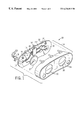
- FIG. 1 is an exploded perspective view of an instrument cluster and its associated printed circuit board used as a signal integration hub;
- FIG. 2 is a schematic diagram of the circuitry of the integration hub of FIG. 1 showing a microcontroller with input circuits receiving signals from various convenience and required function sensors to provide control signals to various actuators;
- FIG. 3 is a flowchart of a program executed by the microcontroller of FIGS. 1 and 2 according to the present invention.
- a signal integration hub 10 may be provided on a printed circuit board 12 such as forms a part of the vehicle instrument cluster 14 .
- the printed circuit board 12 may be supported behind an instrument cluster cowling 28 having apertures 30 for receiving and displaying gauges 22 and lamps 26 .
- the printed circuit board 12 may include a microcontroller 32 communicating via circuit traces 20 ′ with various actuators 44 including vehicle gauges 22 , electronic chimes 24 , and lamps 26 which may be mounted on and connected directly to the printed circuit board 12 .
- the microcontroller 32 may also communicate with convenience sensors 34 and required function 36 located off of the printed circuit board 12 . These sensors 34 and 36 are attached to the microcontroller 32 via conductors 20 attached to connectors 18 received by corresponding connectors 16 on the printed circuit board 12 .
- the signals from convenience sensors 34 and required function sensors 36 may pass through input circuits 40 , prior to being received by the microcontroller 32 , providing battery voltage reference, basic filtering or voltage clamping such as is well known in the art.
- the microcontroller 32 generally includes a microprocessor 31 and associated memory 29 and may include various other components such as oscillators, timers, multiplexers input circuits and A to D converters and D to A converters such as allow it to receive and process various electrical input signals from the convenience sensors 34 and required function sensors 36 and to generate output signals to the actuators 44 .
- Microcontrollers suitable for this purpose are commercially available from a number of suppliers.
- the inputs from the convenience sensors 34 and required function sensors 36 are processed according to a control program 47 contained in memory 29 .
- the control program 47 may respond to the inputs from convenience sensors 32 and required function sensors 34 and its own control logic to actuate actuators 44 .
- Additional output processing circuitry, for example buffer amplifiers 46 may be interposed along conductors 20 and 20 ′ between the microcontroller 32 and the actuators 44 .
- the present invention also provides a voltage measure 48 input to the microcontroller 32 measuring a system voltage of the battery 38 as provided to the printed circuit board 12 by a conductor 20 .
- This voltage measure 48 may be a multi-bit value provided by a dedicated analog to digital converter 50 (as shown) external or internal to the microcontroller 32 or may be a single bit indicating the result of a comparison of a voltage reference to the battery voltage.
- the battery voltage is also provided to the microcontroller 32 for powering the same but only after regulation, filtering and clamping provided by circuitry 51 well understood in the art. The voltage ultimately received by the microcontroller 32 for power is isolated and thus often unrelated to the system voltage.
- the convenience sensors 34 and required function sensors 36 may receive the system voltage as measured by the voltage measure 48 and use it as a reference for their outputs as communicated to the microcontroller 34 or may use the system voltage as a reference for their input circuitry 40 .
- a lowering of the system voltage either through lack of charging of battery 38 or high current demand from other devices such as the vehicle starter can therefore cause erroneously low output signals to the microcontroller 34 from convenience input circuits 40 or sensors 34 .
- the required function sensors 36 are much more indifferent to the system voltage either by design of the sensor or by special preprocessing circuitry 41 not used with the convenience sensors 34 .
- the present invention addresses the problem of erroneous states from input circuit 40 or erroneous output signals from the convenience sensors 34 by a modification of the control program 47 contained in memory 29 .
- control program 47 contains control program 47 contained in memory 29 .
- default values are placed in variables in memory 29 corresponding to each of the convenience sensors 34 . These default values are selected generally so as to provide no alarm condition for gauges 22 , chimes 24 or lamps 26 , but may be any default value considered desirable under the anticipated circumstances in which a low system voltage will occur.
- the voltage measure 48 is interrogated and the microcontroller 32 determines whether the system voltage to the various sensors 34 and 36 is above or below a predetermined threshold, typically nine volts. If the system voltage is below the threshold, then a low voltage flag is set indicated by process block 52 .
- the low voltage flag consists of a bit in memory 29 . Alternatively if the voltage is above the threshold, the low voltage flag is cleared at process block 54 .
- control program 47 then proceeds to process block 56 where the inputs on conductors 20 from the convenience sensors 34 and required function sensors 36 are sampled.
- decision block 58 the low voltage flag is interrogated and if it is not set, indicating that adequate voltage is being provided to the convenience sensors 34 , the control program 47 proceeds to process block 60 and the input signals are debounced and stored. Debouncing involves obtaining successive samples of the inputs until a predetermined number of successive samples shows a consistent value and adopting that consistent value as the debounced input.
- the last stored values for each of the convenience sensors 34 is read.
- the last stored values are those values saved in process block 60 in a previous cycle of the control program 47 . However, they may also be the default values established in process block 49 if no previous cycle of the program has occurred.
- next process block 66 the inputs for the convenience sensors 34 are replaced with their last stored debounced values.
- current debounced values of their signals are used under the assumption that the low system voltage does not affect these inputs for reasons described above.
- the normal processing of the inputs from the convenience sensors 34 and the required function sensors 36 are processed according to the normal operation of the control program.
- all inputs are debounced and used directly while in conditions of low system voltage, the last debounced inputs during a state of normal system voltage are used to replace the raw input values for the convenience sensors 34 only.
- the inputs from the required function sensors 36 which are used directly after debouncing.
Abstract
Description
Claims (14)
Priority Applications (3)
| Application Number | Priority Date | Filing Date | Title |
|---|---|---|---|
| US09/415,842 US6236919B1 (en) | 1999-10-12 | 1999-10-12 | Method and apparatus providing operation of an integration hub for automotive signals during low voltage conditions |
| EP00308656A EP1096343B1 (en) | 1999-10-12 | 2000-10-02 | Method and apparatus providing operation of an integration hub for automotive signals during low voltage conditions |
| DE60009231T DE60009231T2 (en) | 1999-10-12 | 2000-10-02 | Method and device for operating an integrated "hub" for motor vehicle signals during low voltage conditions |
Applications Claiming Priority (1)
| Application Number | Priority Date | Filing Date | Title |
|---|---|---|---|
| US09/415,842 US6236919B1 (en) | 1999-10-12 | 1999-10-12 | Method and apparatus providing operation of an integration hub for automotive signals during low voltage conditions |
Publications (1)
| Publication Number | Publication Date |
|---|---|
| US6236919B1 true US6236919B1 (en) | 2001-05-22 |
Family
ID=23647432
Family Applications (1)
| Application Number | Title | Priority Date | Filing Date |
|---|---|---|---|
| US09/415,842 Expired - Lifetime US6236919B1 (en) | 1999-10-12 | 1999-10-12 | Method and apparatus providing operation of an integration hub for automotive signals during low voltage conditions |
Country Status (3)
| Country | Link |
|---|---|
| US (1) | US6236919B1 (en) |
| EP (1) | EP1096343B1 (en) |
| DE (1) | DE60009231T2 (en) |
Cited By (4)
| Publication number | Priority date | Publication date | Assignee | Title |
|---|---|---|---|---|
| US20040164589A1 (en) * | 2003-02-21 | 2004-08-26 | Visteon Global Technologies, Inc. | Underhood electronic interior integration |
| US20050082866A1 (en) * | 2002-03-27 | 2005-04-21 | Faurecia Innenraum Systeme Gmbh | Device for retaining an instrument cluster and instrument panel |
| US20060069524A1 (en) * | 2004-09-30 | 2006-03-30 | Jatco Ltd. | Malfunction detector for rotation sensor |
| US20110114188A1 (en) * | 2009-11-18 | 2011-05-19 | Chengxuan Fu | Method for operating a tank device especially of a motor vehicle |
Families Citing this family (2)
| Publication number | Priority date | Publication date | Assignee | Title |
|---|---|---|---|---|
| DE102005030612B4 (en) * | 2005-06-30 | 2014-09-11 | Infineon Technologies Ag | Holding device for a sensor signal, method for forwarding a sensor signal and computer program |
| DE102005063616B3 (en) * | 2005-06-30 | 2015-09-10 | Infineon Technologies Ag | Holding device for a sensor signal and method for forwarding a sensor signal |
Citations (8)
| Publication number | Priority date | Publication date | Assignee | Title |
|---|---|---|---|---|
| US4374333A (en) | 1980-05-27 | 1983-02-15 | Sprague Electric Company | Two terminal Hall-sensor |
| US5243324A (en) | 1991-11-07 | 1993-09-07 | Ford Motor Company | Method of detecting a fault in an automotive system |
| US5527187A (en) | 1994-11-17 | 1996-06-18 | Ford Motor Company | Compliant electrical interconnect |
| US5844473A (en) * | 1995-04-12 | 1998-12-01 | Products Research, Inc. | Method and apparatus for remotely collecting operational information of a mobile vehicle |
| US5857159A (en) * | 1994-08-12 | 1999-01-05 | Caterpillar Inc. | Data recording and display system |
| US5880568A (en) * | 1994-10-29 | 1999-03-09 | Robert Bosch Gmbh | Method and arrangement for controlling the drive unit of a vehicle |
| US5968100A (en) * | 1994-07-08 | 1999-10-19 | Hitachi, Ltd. | Vehicle control method and system therefor |
| US6138059A (en) * | 1998-03-10 | 2000-10-24 | Denso Corporation | Vehicle control system and unit for preventing power supply cutoff during re-programming mode |
Family Cites Families (4)
| Publication number | Priority date | Publication date | Assignee | Title |
|---|---|---|---|---|
| US3845370A (en) * | 1973-08-10 | 1974-10-29 | Ibm | Credibility testing in sampled-data systems |
| JPS6084603A (en) * | 1983-08-29 | 1985-05-14 | Akai Electric Co Ltd | Servocontroller |
| FR2676982B1 (en) * | 1991-05-29 | 1998-01-02 | Valeo Electronique | ELECTRIC POWER STEERING DEVICE FOR VEHICLE. |
| US5460327A (en) * | 1994-07-01 | 1995-10-24 | Carrier Corporation | Extended clock thermostat |
-
1999
- 1999-10-12 US US09/415,842 patent/US6236919B1/en not_active Expired - Lifetime
-
2000
- 2000-10-02 DE DE60009231T patent/DE60009231T2/en not_active Expired - Lifetime
- 2000-10-02 EP EP00308656A patent/EP1096343B1/en not_active Expired - Lifetime
Patent Citations (8)
| Publication number | Priority date | Publication date | Assignee | Title |
|---|---|---|---|---|
| US4374333A (en) | 1980-05-27 | 1983-02-15 | Sprague Electric Company | Two terminal Hall-sensor |
| US5243324A (en) | 1991-11-07 | 1993-09-07 | Ford Motor Company | Method of detecting a fault in an automotive system |
| US5968100A (en) * | 1994-07-08 | 1999-10-19 | Hitachi, Ltd. | Vehicle control method and system therefor |
| US5857159A (en) * | 1994-08-12 | 1999-01-05 | Caterpillar Inc. | Data recording and display system |
| US5880568A (en) * | 1994-10-29 | 1999-03-09 | Robert Bosch Gmbh | Method and arrangement for controlling the drive unit of a vehicle |
| US5527187A (en) | 1994-11-17 | 1996-06-18 | Ford Motor Company | Compliant electrical interconnect |
| US5844473A (en) * | 1995-04-12 | 1998-12-01 | Products Research, Inc. | Method and apparatus for remotely collecting operational information of a mobile vehicle |
| US6138059A (en) * | 1998-03-10 | 2000-10-24 | Denso Corporation | Vehicle control system and unit for preventing power supply cutoff during re-programming mode |
Cited By (8)
| Publication number | Priority date | Publication date | Assignee | Title |
|---|---|---|---|---|
| US20050082866A1 (en) * | 2002-03-27 | 2005-04-21 | Faurecia Innenraum Systeme Gmbh | Device for retaining an instrument cluster and instrument panel |
| US6971701B2 (en) * | 2002-03-27 | 2005-12-06 | Faurecia Innenraum Systeme Gmbh | Device for retaining an instrument cluster and instrument panel |
| US20040164589A1 (en) * | 2003-02-21 | 2004-08-26 | Visteon Global Technologies, Inc. | Underhood electronic interior integration |
| US7070229B2 (en) * | 2003-02-21 | 2006-07-04 | Visteon Global Technologies, Inc. | Underhood electronic interior integration |
| US20060069524A1 (en) * | 2004-09-30 | 2006-03-30 | Jatco Ltd. | Malfunction detector for rotation sensor |
| US20110114188A1 (en) * | 2009-11-18 | 2011-05-19 | Chengxuan Fu | Method for operating a tank device especially of a motor vehicle |
| CN102086965A (en) * | 2009-11-18 | 2011-06-08 | 罗伯特.博世有限公司 | Method for operating a tank device especially of a motor vehicle |
| US8675334B2 (en) * | 2009-11-18 | 2014-03-18 | Robert Bosch Gmbh | Method for operating a tank device especially of a motor vehicle |
Also Published As
| Publication number | Publication date |
|---|---|
| DE60009231T2 (en) | 2004-12-30 |
| EP1096343B1 (en) | 2004-03-24 |
| EP1096343A3 (en) | 2002-11-20 |
| DE60009231D1 (en) | 2004-04-29 |
| EP1096343A2 (en) | 2001-05-02 |
Similar Documents
| Publication | Publication Date | Title |
|---|---|---|
| US4336593A (en) | Data processing system for electronic control of automotive vehicle devices with noise prevention | |
| US5948962A (en) | Gas detection system with interchangeable gas sensors | |
| US7137645B2 (en) | Control device for a restraining system in a motor vehicle | |
| GB2046964A (en) | An automatic control system for an automotive vehicle in use with a microcomputer | |
| US7404097B2 (en) | Vehicle-installed microcomputer system that interrupts power to higher accuracy power supply circuit for sensor A/D converter in sleep mode | |
| US6236919B1 (en) | Method and apparatus providing operation of an integration hub for automotive signals during low voltage conditions | |
| JP2009504044A (en) | Method and apparatus for inspecting a first voltage value | |
| GB2129587A (en) | A method of and apparatus for fail-safe operation of a vehicle computer | |
| JP3988609B2 (en) | Oxygen sensor abnormality detection device | |
| CN100538681C (en) | Sensor, controller and the method that is used to monitor at least one sensor | |
| US7248985B2 (en) | Acoustic signature testing for electronic, electromechanical, and mechanical equipment | |
| US7903539B2 (en) | Electronic control unit | |
| EP0902298A3 (en) | Testing method and testing apparatus of electronic circuit | |
| JP3019067B2 (en) | Auxiliary instrument drive | |
| US20040160045A1 (en) | Apparatus for driving on-vehicle occupant-protecting airbag device | |
| KR910002315B1 (en) | Control device for vehicle | |
| US5017910A (en) | Intermittent fault detection system | |
| KR101000259B1 (en) | A Input Switch Circuit with Voltage Divide Resisters in Automobile Which has Reference Voltage, and Method Thereof | |
| US8056538B2 (en) | Method and system to prevent unauthorized uses of engine controllers | |
| US20060156109A1 (en) | Test mode circuit and reset control method therefor | |
| US4816806A (en) | Diagnosis switch | |
| JP2000262669A (en) | Pachinko machine | |
| US20050165529A1 (en) | Short-circuit detecting circuit device | |
| JPH02165069A (en) | Abnormality detector for electric circuit | |
| JPH0950306A (en) | Control system |
Legal Events
| Date | Code | Title | Description |
|---|---|---|---|
| AS | Assignment |
Owner name: FORD MOTOR COMPANY, MICHIGAN Free format text: ASSIGNMENT OF ASSIGNORS INTEREST;ASSIGNORS:CORBIN, BRADLEY JEROME;KANOZA, JEFFREY TODD;REEL/FRAME:010314/0544 Effective date: 19990929 |
|
| AS | Assignment |
Owner name: VISTEON GLOBAL TECHNOLOGIES, INC., MICHIGAN Free format text: ASSIGNMENT OF ASSIGNORS INTEREST;ASSIGNOR:FORD MOTOR COMPANY;REEL/FRAME:010968/0220 Effective date: 20000615 |
|
| STCF | Information on status: patent grant |
Free format text: PATENTED CASE |
|
| FPAY | Fee payment |
Year of fee payment: 4 |
|
| AS | Assignment |
Owner name: JPMORGAN CHASE BANK, N.A., AS ADMINISTRATIVE AGENT Free format text: SECURITY AGREEMENT;ASSIGNOR:VISTEON GLOBAL TECHNOLOGIES, INC.;REEL/FRAME:020497/0733 Effective date: 20060613 |
|
| FPAY | Fee payment |
Year of fee payment: 8 |
|
| AS | Assignment |
Owner name: JPMORGAN CHASE BANK, TEXAS Free format text: SECURITY INTEREST;ASSIGNOR:VISTEON GLOBAL TECHNOLOGIES, INC.;REEL/FRAME:022368/0001 Effective date: 20060814 Owner name: JPMORGAN CHASE BANK,TEXAS Free format text: SECURITY INTEREST;ASSIGNOR:VISTEON GLOBAL TECHNOLOGIES, INC.;REEL/FRAME:022368/0001 Effective date: 20060814 |
|
| AS | Assignment |
Owner name: WILMINGTON TRUST FSB, AS ADMINISTRATIVE AGENT, MIN Free format text: ASSIGNMENT OF SECURITY INTEREST IN PATENTS;ASSIGNOR:JPMORGAN CHASE BANK, N.A., AS ADMINISTRATIVE AGENT;REEL/FRAME:022575/0186 Effective date: 20090415 Owner name: WILMINGTON TRUST FSB, AS ADMINISTRATIVE AGENT,MINN Free format text: ASSIGNMENT OF SECURITY INTEREST IN PATENTS;ASSIGNOR:JPMORGAN CHASE BANK, N.A., AS ADMINISTRATIVE AGENT;REEL/FRAME:022575/0186 Effective date: 20090415 |
|
| AS | Assignment |
Owner name: THE BANK OF NEW YORK MELLON, AS ADMINISTRATIVE AGE Free format text: ASSIGNMENT OF PATENT SECURITY INTEREST;ASSIGNOR:JPMORGAN CHASE BANK, N.A., A NATIONAL BANKING ASSOCIATION;REEL/FRAME:022974/0057 Effective date: 20090715 |
|
| AS | Assignment |
Owner name: VISTEON GLOBAL TECHNOLOGIES, INC., MICHIGAN Free format text: RELEASE BY SECURED PARTY AGAINST SECURITY INTEREST IN PATENTS RECORDED AT REEL 022974 FRAME 0057;ASSIGNOR:THE BANK OF NEW YORK MELLON;REEL/FRAME:025095/0711 Effective date: 20101001 |
|
| AS | Assignment |
Owner name: VISTEON GLOBAL TECHNOLOGIES, INC., MICHIGAN Free format text: RELEASE BY SECURED PARTY AGAINST SECURITY INTEREST IN PATENTS RECORDED AT REEL 022575 FRAME 0186;ASSIGNOR:WILMINGTON TRUST FSB, AS ADMINISTRATIVE AGENT;REEL/FRAME:025105/0201 Effective date: 20101001 |
|
| AS | Assignment |
Owner name: MORGAN STANLEY SENIOR FUNDING, INC., AS AGENT, NEW Free format text: SECURITY AGREEMENT (REVOLVER);ASSIGNORS:VISTEON CORPORATION;VC AVIATION SERVICES, LLC;VISTEON ELECTRONICS CORPORATION;AND OTHERS;REEL/FRAME:025238/0298 Effective date: 20101001 Owner name: MORGAN STANLEY SENIOR FUNDING, INC., AS AGENT, NEW Free format text: SECURITY AGREEMENT;ASSIGNORS:VISTEON CORPORATION;VC AVIATION SERVICES, LLC;VISTEON ELECTRONICS CORPORATION;AND OTHERS;REEL/FRAME:025241/0317 Effective date: 20101007 |
|
| AS | Assignment |
Owner name: VISTEON EUROPEAN HOLDING, INC., MICHIGAN Free format text: RELEASE BY SECURED PARTY AGAINST SECURITY INTEREST IN PATENTS ON REEL 025241 FRAME 0317;ASSIGNOR:MORGAN STANLEY SENIOR FUNDING, INC.;REEL/FRAME:026178/0412 Effective date: 20110406 Owner name: VISTEON INTERNATIONAL HOLDINGS, INC., MICHIGAN Free format text: RELEASE BY SECURED PARTY AGAINST SECURITY INTEREST IN PATENTS ON REEL 025241 FRAME 0317;ASSIGNOR:MORGAN STANLEY SENIOR FUNDING, INC.;REEL/FRAME:026178/0412 Effective date: 20110406 Owner name: VISTEON INTERNATIONAL BUSINESS DEVELOPMENT, INC., Free format text: RELEASE BY SECURED PARTY AGAINST SECURITY INTEREST IN PATENTS ON REEL 025241 FRAME 0317;ASSIGNOR:MORGAN STANLEY SENIOR FUNDING, INC.;REEL/FRAME:026178/0412 Effective date: 20110406 Owner name: VISTEON GLOBAL TREASURY, INC., MICHIGAN Free format text: RELEASE BY SECURED PARTY AGAINST SECURITY INTEREST IN PATENTS ON REEL 025241 FRAME 0317;ASSIGNOR:MORGAN STANLEY SENIOR FUNDING, INC.;REEL/FRAME:026178/0412 Effective date: 20110406 Owner name: VISTEON ELECTRONICS CORPORATION, MICHIGAN Free format text: RELEASE BY SECURED PARTY AGAINST SECURITY INTEREST IN PATENTS ON REEL 025241 FRAME 0317;ASSIGNOR:MORGAN STANLEY SENIOR FUNDING, INC.;REEL/FRAME:026178/0412 Effective date: 20110406 Owner name: VISTEON CORPORATION, MICHIGAN Free format text: RELEASE BY SECURED PARTY AGAINST SECURITY INTEREST IN PATENTS ON REEL 025241 FRAME 0317;ASSIGNOR:MORGAN STANLEY SENIOR FUNDING, INC.;REEL/FRAME:026178/0412 Effective date: 20110406 Owner name: VC AVIATION SERVICES, LLC, MICHIGAN Free format text: RELEASE BY SECURED PARTY AGAINST SECURITY INTEREST IN PATENTS ON REEL 025241 FRAME 0317;ASSIGNOR:MORGAN STANLEY SENIOR FUNDING, INC.;REEL/FRAME:026178/0412 Effective date: 20110406 Owner name: VISTEON SYSTEMS, LLC, MICHIGAN Free format text: RELEASE BY SECURED PARTY AGAINST SECURITY INTEREST IN PATENTS ON REEL 025241 FRAME 0317;ASSIGNOR:MORGAN STANLEY SENIOR FUNDING, INC.;REEL/FRAME:026178/0412 Effective date: 20110406 Owner name: VISTEON GLOBAL TECHNOLOGIES, INC., MICHIGAN Free format text: RELEASE BY SECURED PARTY AGAINST SECURITY INTEREST IN PATENTS ON REEL 025241 FRAME 0317;ASSIGNOR:MORGAN STANLEY SENIOR FUNDING, INC.;REEL/FRAME:026178/0412 Effective date: 20110406 |
|
| FPAY | Fee payment |
Year of fee payment: 12 |
|
| AS | Assignment |
Owner name: CITIBANK., N.A., AS ADMINISTRATIVE AGENT, NEW YORK Free format text: SECURITY INTEREST;ASSIGNORS:VISTEON CORPORATION, AS GRANTOR;VISTEON GLOBAL TECHNOLOGIES, INC., AS GRANTOR;REEL/FRAME:032713/0065 Effective date: 20140409 |
|
| AS | Assignment |
Owner name: VISTEON GLOBAL TECHNOLOGIES, INC., MICHIGAN Free format text: RELEASE OF SECURITY INTEREST IN INTELLECTUAL PROPERTY;ASSIGNOR:MORGAN STANLEY SENIOR FUNDING, INC.;REEL/FRAME:033107/0717 Effective date: 20140409 Owner name: VISTEON SYSTEMS, LLC, MICHIGAN Free format text: RELEASE OF SECURITY INTEREST IN INTELLECTUAL PROPERTY;ASSIGNOR:MORGAN STANLEY SENIOR FUNDING, INC.;REEL/FRAME:033107/0717 Effective date: 20140409 Owner name: VISTEON INTERNATIONAL BUSINESS DEVELOPMENT, INC., Free format text: RELEASE OF SECURITY INTEREST IN INTELLECTUAL PROPERTY;ASSIGNOR:MORGAN STANLEY SENIOR FUNDING, INC.;REEL/FRAME:033107/0717 Effective date: 20140409 Owner name: VISTEON INTERNATIONAL HOLDINGS, INC., MICHIGAN Free format text: RELEASE OF SECURITY INTEREST IN INTELLECTUAL PROPERTY;ASSIGNOR:MORGAN STANLEY SENIOR FUNDING, INC.;REEL/FRAME:033107/0717 Effective date: 20140409 Owner name: VISTEON GLOBAL TREASURY, INC., MICHIGAN Free format text: RELEASE OF SECURITY INTEREST IN INTELLECTUAL PROPERTY;ASSIGNOR:MORGAN STANLEY SENIOR FUNDING, INC.;REEL/FRAME:033107/0717 Effective date: 20140409 Owner name: VISTEON EUROPEAN HOLDINGS, INC., MICHIGAN Free format text: RELEASE OF SECURITY INTEREST IN INTELLECTUAL PROPERTY;ASSIGNOR:MORGAN STANLEY SENIOR FUNDING, INC.;REEL/FRAME:033107/0717 Effective date: 20140409 Owner name: VC AVIATION SERVICES, LLC, MICHIGAN Free format text: RELEASE OF SECURITY INTEREST IN INTELLECTUAL PROPERTY;ASSIGNOR:MORGAN STANLEY SENIOR FUNDING, INC.;REEL/FRAME:033107/0717 Effective date: 20140409 Owner name: VISTEON CORPORATION, MICHIGAN Free format text: RELEASE OF SECURITY INTEREST IN INTELLECTUAL PROPERTY;ASSIGNOR:MORGAN STANLEY SENIOR FUNDING, INC.;REEL/FRAME:033107/0717 Effective date: 20140409 Owner name: VISTEON ELECTRONICS CORPORATION, MICHIGAN Free format text: RELEASE OF SECURITY INTEREST IN INTELLECTUAL PROPERTY;ASSIGNOR:MORGAN STANLEY SENIOR FUNDING, INC.;REEL/FRAME:033107/0717 Effective date: 20140409 |