US6219732B1 - Apparatus and method for wireless communication between a host and a selectively removable module electrically connected to the host - Google Patents
Apparatus and method for wireless communication between a host and a selectively removable module electrically connected to the host Download PDFInfo
- Publication number
- US6219732B1 US6219732B1 US08/782,046 US78204697A US6219732B1 US 6219732 B1 US6219732 B1 US 6219732B1 US 78204697 A US78204697 A US 78204697A US 6219732 B1 US6219732 B1 US 6219732B1
- Authority
- US
- United States
- Prior art keywords
- host
- circuitry
- card
- pcmcia
- host computer
- Prior art date
- Legal status (The legal status is an assumption and is not a legal conclusion. Google has not performed a legal analysis and makes no representation as to the accuracy of the status listed.)
- Expired - Lifetime
Links
Images


Classifications
-
- G—PHYSICS
- G06—COMPUTING; CALCULATING OR COUNTING
- G06F—ELECTRIC DIGITAL DATA PROCESSING
- G06F1/00—Details not covered by groups G06F3/00 - G06F13/00 and G06F21/00
- G06F1/16—Constructional details or arrangements
- G06F1/1613—Constructional details or arrangements for portable computers
- G06F1/1633—Constructional details or arrangements of portable computers not specific to the type of enclosures covered by groups G06F1/1615 - G06F1/1626
- G06F1/1656—Details related to functional adaptations of the enclosure, e.g. to provide protection against EMI, shock, water, or to host detachable peripherals like a mouse or removable expansions units like PCMCIA cards, or to provide access to internal components for maintenance or to removable storage supports like CDs or DVDs, or to mechanically mount accessories
-
- G—PHYSICS
- G06—COMPUTING; CALCULATING OR COUNTING
- G06F—ELECTRIC DIGITAL DATA PROCESSING
- G06F1/00—Details not covered by groups G06F3/00 - G06F13/00 and G06F21/00
- G06F1/16—Constructional details or arrangements
- G06F1/1613—Constructional details or arrangements for portable computers
- G06F1/1615—Constructional details or arrangements for portable computers with several enclosures having relative motions, each enclosure supporting at least one I/O or computing function
- G06F1/1616—Constructional details or arrangements for portable computers with several enclosures having relative motions, each enclosure supporting at least one I/O or computing function with folding flat displays, e.g. laptop computers or notebooks having a clamshell configuration, with body parts pivoting to an open position around an axis parallel to the plane they define in closed position
-
- G—PHYSICS
- G06—COMPUTING; CALCULATING OR COUNTING
- G06F—ELECTRIC DIGITAL DATA PROCESSING
- G06F1/00—Details not covered by groups G06F3/00 - G06F13/00 and G06F21/00
- G06F1/16—Constructional details or arrangements
- G06F1/1613—Constructional details or arrangements for portable computers
- G06F1/1632—External expansion units, e.g. docking stations
-
- H—ELECTRICITY
- H04—ELECTRIC COMMUNICATION TECHNIQUE
- H04M—TELEPHONIC COMMUNICATION
- H04M1/00—Substation equipment, e.g. for use by subscribers
- H04M1/60—Substation equipment, e.g. for use by subscribers including speech amplifiers
- H04M1/6033—Substation equipment, e.g. for use by subscribers including speech amplifiers for providing handsfree use or a loudspeaker mode in telephone sets
-
- H—ELECTRICITY
- H05—ELECTRIC TECHNIQUES NOT OTHERWISE PROVIDED FOR
- H05K—PRINTED CIRCUITS; CASINGS OR CONSTRUCTIONAL DETAILS OF ELECTRIC APPARATUS; MANUFACTURE OF ASSEMBLAGES OF ELECTRICAL COMPONENTS
- H05K5/00—Casings, cabinets or drawers for electric apparatus
- H05K5/02—Details
- H05K5/0256—Details of interchangeable modules or receptacles therefor, e.g. cartridge mechanisms
- H05K5/026—Details of interchangeable modules or receptacles therefor, e.g. cartridge mechanisms having standardized interfaces
- H05K5/0265—Details of interchangeable modules or receptacles therefor, e.g. cartridge mechanisms having standardized interfaces of PCMCIA type
- H05K5/0269—Card housings therefor, e.g. covers, frames, PCB
-
- H—ELECTRICITY
- H05—ELECTRIC TECHNIQUES NOT OTHERWISE PROVIDED FOR
- H05K—PRINTED CIRCUITS; CASINGS OR CONSTRUCTIONAL DETAILS OF ELECTRIC APPARATUS; MANUFACTURE OF ASSEMBLAGES OF ELECTRICAL COMPONENTS
- H05K5/00—Casings, cabinets or drawers for electric apparatus
- H05K5/02—Details
- H05K5/0256—Details of interchangeable modules or receptacles therefor, e.g. cartridge mechanisms
- H05K5/026—Details of interchangeable modules or receptacles therefor, e.g. cartridge mechanisms having standardized interfaces
- H05K5/0265—Details of interchangeable modules or receptacles therefor, e.g. cartridge mechanisms having standardized interfaces of PCMCIA type
- H05K5/0273—Details of interchangeable modules or receptacles therefor, e.g. cartridge mechanisms having standardized interfaces of PCMCIA type having extensions for peripherals, e.g. LAN, antennas
Definitions
- the field of the invention relates to the extensibility of standardized electrical interconnection schemes such as the PCMCIA interface.
- the invention also relates to communication systems between a host system and a selectively removable module, such as a PCMCIA card, the communication system operating while the card is electrically connected to the host system. More particularly, the invention relates to infrared communication systems for communicating between entities sharing the same power supply or that are otherwise electrically connected.
- host systems such as computer systems
- modular additions are specialized cards that fit into a PC mother board or PCMCIA cards that fit into a notebook computer PCMCIA receptacle.
- Such cards are electrically connected to the host system according to a defined interface and typically derive power from the host system in order to operate the circuitry contained therein. The electrical connection further allows communication of data and control information between the two entities.
- the defined interface is composed of physical dimensions such as card size, type of electrical contacts, number of electrical contacts, etc. and operating characteristics, such as signals presented on each contact, timing of signals, and/or scheme of operation.
- Such standardization allows manufacturers other than the host system manufacturer to create the extensible modules for interacting with the host system.
- PCMCIA standard as a representative example and not by way of limitation.
- the concepts illustrated in connection with the present invention as used with a PCMCIA card can be applied to any standardized interface.
- the PCMCIA standard has defined digital signals (e.g., binary data) and control signals in order to transfer digital information between card and host.
- digital signals e.g., binary data
- control signals in order to transfer digital information between card and host.
- the PCMCIA standard does not have facility for analog signals a significant limitation depending on the functionality of a given PCMCIA card.
- a representative example throughout this application is that of a speakerphone incorporated on a PCMCIA modem card using a host system microphone and speaker as part of its implementation. Because of such an arrangement, the PCMCIA card requires the analog signal to pass from the microphone to the PCMCIA card and for control thereon before being communicated through the telephone line connector found on the PCMCIA card. Likewise, analog signals will need to be communicated from the PCMCIA modem card to the speaker located on the host system. There needs to be some way to communicate this analog signal between the host system and the PCMCIA card. This particular representative example and the implementation thereof along with the present invention will be shown in more detail hereafter.
- a host system manufacturer will include one or perhaps two defined interfaces for the interconnection of cards or other extensible modules and if they are not chosen by component manufacturer, there will not be a ready market for the card. It is economically infeasible to attempt to persuade all manufacturers to adopt a custom interface when standards exist that allow most functionality to be implemented therein. It is naturally more desirable to simply extend the existing standard in some fashion in order to accomplish the particular purposes of a selectively removable card or module designer.
- Multiplexing the signals found on a standardized connection such as the PCMCIA interface uses the same physical or mechanical connection and simply shares the signal band width between the PCMCIA standard protocol and the extension provided by the selectively removable card designer in order to accomplish the desired task.
- analog voice signals would be mixed with the PCMCIA digital signals in order to transfer voice signals to and from a PCMCIA card (and phone line) and the host system microphone and speaker.
- the drawbacks encountered include an overburdening of the signals carried on the respective PCMCIA contacts that leads to errors, inefficient operation, and sometimes a performance degradation. Additionally, conflicts may occur with the PCMCIA architecture such that normal communications between the card and the host are sometimes interrupted. Finally, the amount of data communicated between card and host may be insufficient for an application because of the reduction in available band width due to sharing the signals.
- a side pin can be mounted on the frame of a PCMCIA card for interaction with the corresponding receptacle found within the card guide mounted on the host or other location.
- Other variations include forms of spring contacts to engage to two metal components, one located on the card frame and the other located on the card guide or otherwise mounted at the host.
- electromechanical connections have been found in many instances to lack solid contact and therefore are less reliable. Furthermore, they are susceptible to increases wear during normal operation because of the location of the electromechanical location. Finally, such a sidepin connection can be very expensive due to the extensive modifications made to the card frame and to the card guide adding additional components.
- a PC will have in many instances a sound card having a line out connection or a line in connection in order to handle specifically analog voice signals.
- a final method of extending the capabilities of a given interface uses external cables to connect the analog data input or output from a sound card to an external connection on the PCMCIA card itself. In this manner, the voice data can be communicated through this external cable and causing no interference with the normal PCMCIA connection.
- Such an external cable and connector arrangement is cumbersome and unwieldy and requires more physical componentry on the card which in turn increases manufacturing complexity and expense.
- the external cable or cables are ever present and add to overall desktop clutter. Since a PCMCIA card is used in many instances for use with a portable notebook computer that is set up and taken down often, the additional time and effort for connecting yet another cable is bothersome.
- an object of the present invention to allow wireless communication between a host and a selectively removable card electrically connected to the host without utilizing any hardware external to the host housing.
- the present invention incorporates a wireless communications channel between a host system and a selectively removable card electrically connected within the host system
- the host system and the selectively removable card will share the same power supply to power the circuitry found on each but will communicate at least a portion of the data between them through the wireless communications channel. They may also, and in fact typically do, communicate information through a standardized connection, such as a PCMCIA interface that provides connection between them.
- the wireless communications channel is used to overcome limitations in such a standardized interface.
- the PCMCIA interface defines all of the pin or contact connections thereby making it impossible for a designer to add additional signals to be communicated between the host system and a PCMCIA card.
- One exemplary embodiment of the present invention extends the PCMCIA interface so that analog voice data can be communicated between a selectively removable PCMCIA card and a host (typically a notebook computer) that has a speaker and a microphone contained therein.
- a selectively removable PCMCIA card and a host (typically a notebook computer) that has a speaker and a microphone contained therein.
- One application of such an exemplary embodiment is to create a speakerphone with the PCMCIA card providing the interconnection to a standard phone jack. If the selectively removable PCMCIA card can receive and transmit analog voice signals, then the card may be configured to act as a speakerphone. This is a particularly beneficial extension to a PCMCIA card already configured to be a data modem that are currently prevalent and popular with owners of notebook computers.
- a wireless communications channel comprises a first and second wireless signal transfer means thereby making up a bi-directional data channel.
- One wireless signal transfer means resides on the PCMCIA card while the other wireless signal transfer means resides on the host and the two are so oriented that communications can occur between them.
- an infrared emitting LED and a photo transistor to receive and respond to infrared emissions can comprise each of the two signal transfer means and would be so oriented that the infrared light emitted from the IR LED may easily reach the corresponding photo transistor.
- the present invention could be embodied as a unidirectional channel between either the host to the selectively removable card or between the selectively removable card and the host. Such unidirectional implementations would be considered within the scope of the present invention.
- the infrared LED or emitter and photo transistor for the PCMCIA card can be positioned to transmit and receive through the top or bottom cover portion of the jacket of the PCMCIA card or through the side or frame area of the PCMCIA card.
- two common techniques are employed. First, a smokey gray plastic similar to that found in consumer electronic remote controls can be used to cover the area where the IR LED and photo transistor are located such as the covers or side frames. This is particularly convenient for side transmission of the signal transfer means since they can be simply mounted on the PCMCIA card circuit board with no additional hardware or mechanical additions that will in turn minimize the manufacturing cost of the present invention.
- Another method is to bore appropriately sized holes to allow the infrared emissions to occur through the PCMCIA card, this typically occurring in the jacket or the side chassis. In general, any form of packaging that allows the infrared light to pass can be utilized.
- radio frequency or ultrasonic frequency devices could be used in place of infrared LEDs and corresponding photo transistors.
- FIG. 1 is a perspective drawing of a notebook computer having a PCMCIA card inserted therein that is connected both to a telephone and a phone line for use in a unique speakerphone application illustrating the present invention
- FIG. 2 is an exploded perspective view of a PCMCIA card incorporating one embodiment of the present invention wherein the infrared transmission and reception means operate through orifices in the upper jacket of the PCMCIA card;
- FIG. 3 is a cutaway perspective of a PCMCIA card of FIG. 2 while the card is inserted in its receptacle and showing communication between the card and the host computer;
- FIG. 4 is an exploded perspective view of a PCMCIA card incorporating another embodiment of the present invention wherein the infrared transmission and reception means operate through the upper jacket constructed of an infrared permeable material;
- FIG. 5 is a cutaway perspective of a PCMCIA card of FIG. 4 while the card is inserted in its receptacle and showing communication between the card and the host computer;
- FIG. 6 is an exploded perspective of a PCMCIA card incorporating another embodiment of the present invention wherein the infrared transmission and reception means operate through orifices in the side of the PCMCIA chassis.
- FIG. 7 is cutaway perspective of the PCMCIA card of FIG. 6 showing how the wireless signal transfer means operates through the chassis of the PCMCIA card to interact with corresponding wireless signal transfer means on the host computer within the host housing;
- FIG. 8 is an exploded perspective of a PCMCIA card incorporating another embodiment of the present invention wherein the infrared transmission and reception means operate through the side of the PCMCIA chassis constructed of an infrared permeable material;
- FIG. 9 is cutaway perspective of the PCMCIA card of FIG. 8 showing how the wireless signal transfer means operates through the side of the PCMCIA card to interact with corresponding wireless signal transfer means on the host computer within the host housing;
- FIG. 10 is a block schematic diagram of a speakerphone application using a PCMCIA card in a host computer in communicating using wireless transmitters and receivers to communicate between the PCMCIA card and the host computer;
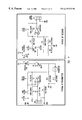
- FIG. 11 is a schematic diagram showing sample implementations of a typical infrared transmitter and a typical infrared receiver.
- wireless signal transfer means refers to any known method and/or apparatus for transmitting and receiving analog or digital signals from one point to another point.
- the medium for transmitting the signals may be light waves, including infrared light, radio waves, ultrasonic waves, or any other waves along the electromagnetic spectrum.
- infrared LEDs to transmit a signal and phototransistors that are sensitive to infrared light to receive the signal are shown as an example of a wireless signal transfer means.
- This form of wireless signal transfer means is shown by way of example and not by limitation and those skilled in the art will undoubtedly understand and appreciate various different ways of transmitting a signal without the use of wires or other physical implements between two points.
- selectively removable module refers to a component that is optional to the normal functioning of a host computer system. Such a module will receive power from the host system to power its internal circuitry and may optionally communicate with the host through an electromechanical interface to transmit and receive data and control information. Shown by way of example and not by limitation throughout this application is a selectively removable module in the form of a PCMCIA component card that communicates through the PCMCIA interface. Other examples of selectively removable modules include but are not limited to standard computer add-in cards such as sound cards, data acquisition cards, modems, video cards, etc. but would also include chips and other modules that connect directly to a computer mother board, other add-in components such as SIMMs used for memory, etc.
- FIG. 1 shows a notebook computer 20 having a PCMCIA card 22 inserted therein, the PCMCIA card 22 and notebook computer 20 cooperating to form a speakerphone.
- the notebook computer 20 has a microphone 24 and a speaker 25 that will be used in implementing the speakerphone according to the present invention.
- Notebook 20 also has an external housing 26 that encompasses and encloses all the internal computer circuitry.
- the PCMCIA card 22 acts as a selectively removable module that can be inserted and electronically coupled with the internal computer circuitry of the notebook computer 20 .
- the PCMCIA card 22 has an external jacket that encompasses and encloses its internal circuitry with at least a portion thereof contained within the external housing 26 of the notebook computer 20 .
- the PCMCIA card 22 also has a RJ11 jack 30 extending therefrom that has a phone cord 32 connected thereto by RJ11 plug 31 that will electrically connect the PCMCIA card internal circuitry to a phone line. Also, the PCMCIA card 22 connects to a special IO connector 34 that is connected to a telephone by phone line 40 . An off-hook detect mechanism is found within the IO connector 34 and comprises internal circuitry to determine when a telephone is in the off-hook state so that this status can be communicated to the PCMCIA card in order to disable the speakerphone. These components are necessary for interfacing the PCMCIA card 22 controlling the speakerphone with the phone network through phone line 32 and with a standard telephone through phone line 40 .
- the internal circuitry of the PCMCIA card 22 in conjunction with the circuitry of the notebook computer 20 will provide a speakerphone application utilizing the available microphone 24 and speaker 25 incorporated into the notebook computer 20 .
- microphone 24 may be replaced by a sound card and externally connected microphone and be functionally equivalent for purposes of this speakerphone application.
- the speaker 25 may be replaced by external speakers connected to a standard sound card.
- signals are transferred between the PCMCIA card 22 and the notebook computer 20 internal circuitry by way of a wireless signal transfer means thereby implementing the present invention as shown hereafter.
- FIG. 2 is an exploded perspective drawing of an exemplary embodiment of the present invention as used in the notebook computer 20 of FIG. 1 incorporating the unique communication apparatus of the present invention and for implementing a speakerphone.
- the PCMCIA modem card comprises an upper jacket piece 41 , a lower jacket piece 43 , and an internal circuit assembly 45 .
- the upper and lower jacket pieces, 41 and 43 respectively, encompass the internal circuit assembly to form the exterior confines of the card.
- the internal circuitry assembly 45 is composed of a circuit board 47 populated with various components interconnected so as to provide modem functionality (or alternatively other functionality). Encircling the circuit board 47 , is a supporting frame 51 and a host computer interface 49 .
- the host computer interface 49 is electrically coupled to the circuitry on the circuit board 47 so as to provide an electrical connection to the host computer system, typically a notebook computer. In this example, the host computer interface 49 is configured according to the PCMCIA standard.
- an IO receptacle 53 and an RJ11 jack assembly 55 are electronically coupled to the circuit board 47 .
- the RJ11 jack assembly 55 is composed an RJ11 jack 57 fit within a RJ11 jack base 59 that is selectively extensible with respect to the supporting frame 51 by way of a spring mechanism assembly 61 . This allows the RJ11 jack to be either extended away from the main body of the PCMCIA card or stored internal to the card. This is useful for allowing the jack to be internally stored when not in use so as to keep all aspects of the PCMCIA card within the external housing of the host computer environment.
- a phototransistor 63 that is sensitive to infrared light and an infrared LED 65 that emits infrared light.
- a complementary infrared LED is found on the host computer system in line with the phototransistor 63 and a complementary phototransistor is found on the host system in line with infrared LED 65 .
- the upper jacket piece 41 has orifice 73 and orifice 75 that allow infrared light signals to pass uninhibited.
- orifices may be contained in the lower jacket piece 43 and the infrared LED 65 and the phototransistor 63 properly placed on the bottom side of the circuit board 47 .
- the upper jacket piece 41 and the lower jacket piece 42 are typically constructed of steel about 0.008 inch in thickness and the orifices are bored into the respective pieces according to embodiment and configuration.
- Exemplary phototransistors used in this and other embodiments would be model LPT-80A or model SFH307 phototransistors available from Siemens. Equivalent to phototransistors as used throughout this application would be a photodiode accompanied by a gain circuit as would be known by those skilled in the art. Exemplary infrared emitter or LED would be model IRL 81A or model IRA 81A, again from Siemens.
- FIG. 3 is a cutaway view of the PCMCIA card inserted in a notebook computer with the infrared LED and infrared sensitive phototransistor being completely within the confines of the external host computer housing for the embodiment shown in FIG. 2.
- a PCMCIA modem card 67 is inserted into a PCMCIA receptacle 69 that is electrically coupled to the host computer mother board 71 .
- the PCMCIA modem card 67 also has a RJ11 jack assembly 55 shown in the extended position for interfacing with a phone network.
- the infrared sensitive phototransistor 75 and the infrared LED 77 are at a position completely within the external housing 67 of the host computer system. It may be noted that while a notebook computer is shown in this example, that any computer system may be used as the host computer system such as a desk top computer systems, palm top computer systems, video game systems, and a variety of consumer electronics, etc.
- an infrared LED 79 and infrared sensitive phototransistor 81 are connected to a base 83 and electronically connected to the host computer system circuit board 71 through connection means 85 .
- the infrared LED 79 and the infrared sensitive transistor 81 that are electrically connected to the host computer system circuit board 71 are again completely enclosed within the host computer system housing 87 .
- the infrared LED 79 is linearly aligned with the infrared sensitive phototransistor 63 and the infrared sensitive phototransistor 81 is linearly aligned with the infrared LED 65 so as to allow signals to pass between the respective LED-photo-transistor pairs found on the PCMCIA modem card 67 and base 83 to allow bi-directional wireless signal transfer between the PCMCIA modem card 67 and the host computer circuit board 71 through orifices 73 and 75 , respectively.
- infrared transparent materials may be used in PCMCIA card construction as will be shown hereafter in connection with another embodiment.
- the transmission componentry may be placed anywhere within the PCMCIA modem card 67 so long as they are linearly aligned with corresponding IR componentry electrically connected to the host computer system circuit board 71 .
- the infrared LED 79 and the infrared sensitive phototransistor 81 may be mounted on the host computer system circuit board 71 with the corresponding infrared sensitive phototransistor 63 and infrared LED 65 mounted on the back side of the PCMCIA modem card 67 circuit board 47 to avoid having a separate base 83 and electrical connection means 85 .
- the lower jacket piece 43 of the PCMCIA modem card 67 would have to let infrared light pass uninhibited through holes, transparent material, or in some other manner.
- FIG. 4 is an exploded perspective drawing of another embodiment of the present invention as used in the notebook computer 20 of FIG. 1 incorporating the unique communication apparatus of the present invention and for implementing a speakerphone.
- the PCMCIA modem card comprises an upper jacket piece 42 , a lower jacket piece 44 , and an internal circuit assembly 46 .
- the upper and lower jacket pieces, 42 and 44 respectively, encompass the internal circuit assembly to form the exterior confines of the card.
- the internal circuitry assembly 46 is composed of a circuit board 48 populated with various components interconnected so as to provide modem functionality (or alternatively other functionality). Encircling the circuit board 48 , is a supporting frame 52 and a host computer interface 50 .
- the host computer interface 50 is electrically coupled to the circuitry on the circuit board 48 so as to provide an electrical connection to the host computer system, typically a notebook computer. In this example, the host computer interface 50 is configured according to the PCMCIA standard.
- an IO receptacle 54 and an RJ11 jack assembly 56 are electronically coupled to the circuit board 48 .
- the RJ11 jack assembly 56 is composed an RJ11 jack 58 fit within a RJ11 jack base 60 that is selectively extensible with respect to the supporting frame 52 by way of a spring mechanism assembly 62 . This allows the RJ11 jack to be either extended away from the main body of the PCMCIA card or stored internal to the card. This is useful for allowing the jack to be internally stored when not in use so as to keep all aspects of the PCMCIA card within the external housing of the host computer environment.
- a phototransistor 64 that is sensitive to infrared light and an infrared LED 66 that emits infrared light.
- a complementary infrared LED is found on the host computer system in line with the phototransistor 64 and a complementary phototransistor is found on the host system in line with infrared LED 66 .
- the upper jacket piece 42 is made of a material that will allow infrared light signals to pass uninhibited. In this manner, signals can be transferred in a wireless manner between the circuitry found on circuit board 48 and the host computer system circuitry without passing through the host computer interface 50 to form a bi-directional wireless data communication channel.
- LEXAN® resin available from the General Electric plastics division of the General Electric Company located at One Plastics Avenue, Pittsfield, Mass. 01201. As used in this embodiment, visible light transmission is inhibited, infrared light transmission is permitted, and the material has a physical “look” of being black.
- FIG. 5 is a cutaway view of the PCMCIA card inserted in a notebook computer with the infrared LED and infrared sensitive phototransistor being completely within the confines of the external host computer housing for the embodiment shown in FIG. 4.
- a PCMCIA modem card 68 is inserted into a PCMCIA receptacle 70 that is electrically coupled to the host computer mother board 72 .
- the PCMCIA modem card 68 also has a RJ11 jack assembly 56 shown in the extended position for interfacing with a phone network.
- the infrared sensitive phototransistor 76 and the infrared LED 78 are at a position completely within the external housing 68 of the host computer system.
- an infrared LED 80 and infrared sensitive phototransistor 82 are connected to a base 84 and electronically connected to the host computer system circuit board 72 through connection means 86 .
- the infrared LED 80 and the infrared sensitive transistor 82 that are electrically connected to the host computer system circuit board 72 are again completely enclosed within the host computer system housing 88 .
- the infrared LED 80 is linearly aligned with the infrared sensitive phototransistor 64 and the infrared sensitive phototransistor 82 is linearly aligned with the infrared LED 66 so as to allow signals to pass between the respective LED-photo-transistor pairs found on the PCMCIA modem card 68 and base 84 to allow bi-directional wireless signal transfer between the PCMCIA modem card 68 and the host computer circuit board 72 .
- FIG. 6 shows another embodiment of a PCMCIA modem card with the infrared transmitting and receiving circuitry located along the PCMCIA card edge or side and the transmission occurs through holes bored in the side frame.
- FIG. 6 is an exploded perspective view of a PCMCIA modem card according to this alternative embodiment.
- An upper jack piece 92 and a lower jacket piece 94 encompass an internal circuitry assembly 96 in order to form the PCMCIA modem card.
- the upper jacket piece 92 and the lower jacket piece are constructed of standard materials, typically metal.
- the internal circuit assembly 96 has a circuit board 98 having componentry for a standard telecommunication modem.
- the circuit board 98 is electrically connected to a host computer interface 100 that will be used to connect the circuit board 98 with the host computer circuit board.
- a supporting frame 102 holds the circuit board 98 , as well as the host computer interface 100 , a IO receptacle 104 , and an RJ11 jack assembly 106 .
- the RJ11 jack assembly 106 has a RJ11 jack 108 formed within a RJ11 jack base 110 that is capable of being in a position inside of the assembled PCMCIA modem or in a position extending out from the PCMCIA modem to allow a mating RJ11 plug to be inserted into the RJ11 Jack 108 .
- the spring mechanism assembly 112 allows RJ11 jack base 110 to easily and selectively extend and retract between a storage position with RJ11 jack 108 located within the PCMCIA modem card and an extended operational position.
- an infrared sensitive phototransistor 114 and an infrared LED 116 are mounted on the circuit board 98 so that they may emit and receive infrared signals through orifices 118 and 120 , respectively, located within the supporting frame 102 . This will allow infrared signal transmission through the supporting frame and the corresponding card guide to mating infrared sensitive phototransistor and IR emitter electrically connected to the host computer system mother board.
- FIG. 7 is a cutaway perspective view of the PCMCIA modem card 122 of FIG. 6 as it appears when inserted into a PCMCIA receptacle of a host computer system such as a notebook system as shown in FIG. 1 .
- the PCMCIA receptacle 124 is electrically connected to a host computer circuit board 126 that is populated with the host computer circuitry.
- the infrared sensitive phototransistor 114 and the infrared LED 116 located on the PCMCIA modem card 122 circuit board 98 are completely within the host housing 128 .
- an infrared LED 130 and infrared sensitive phototransistor 132 are also, on the host computer circuit board 126 . These components allow the receipt and transmission of IR signals from the host computer circuit board 126 in another location.
- infrared LED 130 on host computer circuit board 126 is positioned so as to be linearly aligned with the infrared sensitive phototransistor 114 located on the modem circuit board 98 so that signals may be transmitted from the infrared LED 130 and received by the infrared sensitive phototransistor 114 thereby providing a communication path from the host computer circuit board 126 to the modem circuit board 98 .
- orifice 118 allows the infrared signal to pass directly between the infrared LED 130 and the infrared sensitive phototransistor 114 .
- the infrared sensitive phototransistor 132 located on the host computer circuit board 128 may receive infrared signals through orifice 120 from the infrared LED 116 located on the modem circuit board 98 . In this manner, signals may travel from the modem circuit board 98 to the host computer circuit board 126 .
- FIG. 8 shows another embodiment of a PCMCIA modem card with the infrared transmitting and receiving circuitry located along the side of the supporting frame with the signal transmitted through the supporting frame constructed infrared transparent material.
- FIG. 8 is an exploded perspective view of a PCMCIA modem card according to this alternative embodiment.
- An upper jack piece 91 and a lower jacket piece 93 encompass an internal circuitry assembly 95 in order to form the PCMCIA modem card.
- the upper jacket piece 91 and the lower jacket piece 93 are constructed of standard materials, typically metal.
- the internal circuit assembly 95 has a circuit board 97 having componentry for a standard telecommunication modem.
- the circuit board 97 is electrically connected to a host computer interface 99 that will be used to connect the circuit board 97 with the host computer circuit board.
- a supporting frame 101 holds the circuit board 97 , as well as the host computer interface 99 , a IO receptacle 103 , and an RJ11 jack assembly 105 .
- the RJ11 jack assembly 105 has a RJ11 jack 107 formed within a RJ11 jack base 109 that is capable of being in a position inside of the assembled PCMCIA modem or in a position extending out from the PCMCIA modem to allow a mating RJ11 plug to be inserted into the RJ11 jack 107 .
- the spring mechanism assembly 111 allows RJ11 jack base 109 to easily and selectively extend and retract between a storage position with RJ11 jack 107 located within the PCMCIA modem card and an extended operational position.
- an infrared sensitive phototransistor 113 and an infrared LED 115 Mounted on the circuit board 97 is an infrared sensitive phototransistor 113 and an infrared LED 115 .
- the infrared sensitive phototransistor 113 and IR emitter 115 are oriented in a sideways position so that they may emit and receive infrared signals through the supporting frame 101 that is constructed of an infrared transparent material such as LEXAN®. This will allow infrared signal transmission through the supporting frame 101 and the corresponding card guide to mating infrared sensitive phototransistor and IR emitter electrically connected to the host computer system mother board.
- FIG. 9 is a cutaway perspective view of the PCMCIA modem card 121 of FIG. 8 as it appears when inserted into a PCMCIA receptacle of a host computer system such as a notebook system as shown in FIG. 1 .
- the PCMCIA receptacle 123 is electrically connected to a host computer circuit board 125 that is populated with the host computer circuitry.
- the infrared sensitive phototransistor 113 and the infrared LED 115 located on the PCMCIA modem card 121 circuit board 97 are completely within the host housing 127 .
- an infrared LED 129 and infrared sensitive phototransistor 131 are all within the host housing 127 .
- infrared LED 129 on host computer circuit board 125 is positioned so as to be linearly aligned with the infrared sensitive phototransistor 113 located on the modem circuit board 97 so that signals may be transmitted from the infrared LED 129 and received by the infrared sensitive phototransistor 113 thereby providing a communication path from the host computer circuit board 125 to the modem circuit board 97 .
- the supporting frame is constructed of a material that allows infrared signals to pass uninhibited.
- the infrared sensitive phototransistor 131 located on the host computer circuit board 127 may receive infrared signals through the transparent supporting frame 101 from the infrared LED 115 located on the modem circuit board 97 . In this manner, signals may travel from the modem circuit board 97 to the host computer circuit board 125 .
- FIG. 10 is a schematic block diagram showing the componentry that can be added to a standard PCMCIA modem card and host computer system in order to implement a speakerphone.
- the PCMCIA card will include the functional componentry included within the box 134 .
- the host computer will incorporate functionality enclosed within the box 136 .
- a telephone 138 is hooked by a phone cable 140 to an off-hook detect circuit 142 .
- the off-hook detect circuit 142 is part of a physical IO connector and cable represented by box 144 that will hook into a PCMCIA card through a pin IO receptacle 146 (shown in FIG. 1 as part of the IO connection 34 ).
- the off-hook detect hook circuit 142 will determine whether or not the telephone 138 is in use so that the speakerphone may be disabled when a user picks up the handset of telephone 138 .
- a phone cable 148 connects the PCMCIA card as represented by box 134 through RJ11 connection 150 to the phone network 152 .
- Both the pins from the IO receptacle 146 and the RJ11 connection 150 are fed into a data access arrangement 154 for digital processing. This is accomplished through passing the signals from the data access arrangement 154 to a line CODEC 156 and onto a data signal processing echo canceler 158 .
- the data access arrangement (DAA) 154 is the circuitry necessary for accessing or transmitting an analog signal according to the requirements of communications network to which the PCMCIA card 134 is attached. This includes opto-isolators, transformers, and other mechanisms standard in the art allowing connection between systems having different electrical characteristics and requirements.
- the line CODEC 156 digitizes the signal taken off of the phone line as received from the data access arrangement 154 by way of an analog-to-digital converter. This allows the signal data to be manipulated by echo cancellation circuit 158 or any other digital signal processing that may be required.
- the digital signal will be converted to an analog signal by the audio CODEC 194 before being transmitted through a wireless communications channel to the host computer 136 as will be explained in more detail hereafter.
- the logical block diagram shows two separate CODECs, line CODEC 156 and audio CODEC 194 , residing on the PCMCIA card 134 . This is only illustrative of function and those skilled in the art will see that the same CODEC may perform the same function depending on physical implementation.
- a microcontroller 160 controls the digital signal processing echo cancellation circuit 158 as well as provides an interface with the rest of the modem circuitry not shown in FIG. 10 . Furthermore, to provide such interfacing behavior, the microcontroller 160 accesses RAM 162 and ROM 164 for programming and calculations as well as a custom ASIC 166 for interfacing through the PCMCIA interface 168 to electrically communicate with the host computer system.
- a microphone 170 and a speaker 172 that are used as part of the speakerphone implementation. Signals from the speaker 170 will eventually reach the digital processing echo canceler 158 as controlled by microcontroller 160 and signals broadcast through the speaker 172 will be signals originating from the digital signaling processing echo canceler 158 as controlled by the microcontroller 160 .
- an analog signal is received from a microphone biasing circuit 174 representing the voice signal that is amplified in amplifier 176 before running through stereo CODEC 178 .
- the stereo CODEC 178 may be used to digitize the analog voice signal received from the microphone in order to store the information on the disk drive of the host computer system. This would be useful for an answering machine implemented as part of the system and other applications requiring the storage of voice data.
- the stereo CODEC 178 can be controlled by host computer system software in order implement a gain control function for adjusting the volume of the signal as perceived through the speaker 172 . In this manner, the stereo CODEC 178 could be making an analog-to-analog conversion of the signal implementing the desired signal gain affects.
- the stereo CODEC 178 allows signals from different sources to be mixed.
- an answering machine implementation could allow the incoming analog signal transmitted from the PCMCIA card and the stored digital signal being heard by the caller to be mixed and simultaneously monitored through the speaker 172 on the host computer 136 .
- the analog signal After processing in the stereo CODEC 178 , the analog signal will be run through a transmission amplifier 180 and pass through a temperature compensated current source 182 before being transmitted from an infrared LED 184 .
- the temperature compensated current source 182 is for assuring that proper signal levels are transmitted at the infrared LED 184 over temperature.
- the infrared LED 184 sends an infrared signal (analog) across to an infrared sensitive transistor 186 as represented by transmit arrows 188 and receive arrows 190 .
- microphone speech data is transmitted to the PCMCIA modem card for processing through a wireless data channel without burdening the PCMCIA interface. This is necessary in order to have enough information band width preserve high speech quality by sending an adequate amount of information for processing.
- the signal received by the infrared sensitive phototransistor 186 is amplified through a receiver amp 192 before being passed onto audio CODEC 194 for conversion from analog to digital format and processed through the digital system processing echo cancellation circuitry 158 .
- Signals to be transmitted on speaker 172 will originate from the phone or phone line, pass through line CODEC 156 for conversion to digital format, pass through the digital signal processing echo cancellation circuitry 158 , pass through audio CODEC 194 for conversion back to analog format, and arrive at transmission amplifier 196 that prepares the signal for transmission from the PCMCIA modem card to the host computer. Again, the signal passes through a temperature compensated current source 198 in order to assure that a consistent transmit level will be found at the infrared LED 200 over temperature.
- Transmission occurs between the infrared LED 200 found on the PCMCIA modem card and the infrared sensitive phototransistor 202 found on the host computer as shown by transmit arrows 204 and receive arrows 206 . Again, this will occur in a linear orientation and will be facilitated by orifices in the PCMCIA modem card or some form of covering that will allow the infrared signal to transfer uninhibited.
- Analog signal transmission has the advantage of typically being less costly to implement since the signal may be transmitted over a single infrared LED/phototransistor pair (or two pairs for full-duplex operation as shown). Digital transmission may require more infrared LED/phototransistor pairs due to the timing signals, bus widths, etc. associated with digital signals. The added hardware increases cost and may be prohibitive depending on the specific application.
- the present invention contemplates wireless transfer of signals as explained regardless of signal format.
- the signal passes through a receiver amplifier 208 to strengthen the signal before passing through the stereo CODEC 178 and on to the actual speaker amplifier 210 before being heard through speaker 172 .
- the stereo CODEC 178 may digitize the analog signal received for storage at the host computer 136 .
- the transmission and reception of the infrared signal occurs without any mechanical connection.
- the respective infrared transmitter (LED) and infrared receiver (infrared sensitive photo transistor) are simply placed in a physical orientation so that the transmission may occur uninhibited.
- any form of wireless transmission means may be used to accomplish the same data transmission channel.
- a low strength radio signal could be transmitted and received between PCMCIA card and host computer to effectuate the same data transmission capabilities and again without burdening the electromechanical connection through the PCMCIA interface.
- FIG. 11 shows a typical IR transmitter and a typical IR receiver that can be implemented as part of the infrared transmission wireless signal transfer link as explained previously. Those skilled in the art will recognize how to use such a circuit and may incorporate other circuits of equivalent purpose but achieving the same transmission and reception and capabilities.
Landscapes
- Engineering & Computer Science (AREA)
- Computer Hardware Design (AREA)
- Theoretical Computer Science (AREA)
- General Engineering & Computer Science (AREA)
- Physics & Mathematics (AREA)
- Human Computer Interaction (AREA)
- General Physics & Mathematics (AREA)
- Microelectronics & Electronic Packaging (AREA)
- Signal Processing (AREA)
- Mathematical Physics (AREA)
- Optical Communication System (AREA)
- Mobile Radio Communication Systems (AREA)
Abstract
Description
Claims (8)
Priority Applications (1)
| Application Number | Priority Date | Filing Date | Title |
|---|---|---|---|
| US08/782,046 US6219732B1 (en) | 1997-01-10 | 1997-01-10 | Apparatus and method for wireless communication between a host and a selectively removable module electrically connected to the host |
Applications Claiming Priority (1)
| Application Number | Priority Date | Filing Date | Title |
|---|---|---|---|
| US08/782,046 US6219732B1 (en) | 1997-01-10 | 1997-01-10 | Apparatus and method for wireless communication between a host and a selectively removable module electrically connected to the host |
Publications (1)
| Publication Number | Publication Date |
|---|---|
| US6219732B1 true US6219732B1 (en) | 2001-04-17 |
Family
ID=25124787
Family Applications (1)
| Application Number | Title | Priority Date | Filing Date |
|---|---|---|---|
| US08/782,046 Expired - Lifetime US6219732B1 (en) | 1997-01-10 | 1997-01-10 | Apparatus and method for wireless communication between a host and a selectively removable module electrically connected to the host |
Country Status (1)
| Country | Link |
|---|---|
| US (1) | US6219732B1 (en) |
Cited By (18)
| Publication number | Priority date | Publication date | Assignee | Title |
|---|---|---|---|---|
| US20020108008A1 (en) * | 2000-12-13 | 2002-08-08 | Kyun-Hoe Park | Computer system having improved interface |
| WO2002097640A1 (en) * | 2001-05-28 | 2002-12-05 | Ascom Ag | Device comprising electronic modules and a method for operating the same |
| US6491533B2 (en) * | 2000-12-14 | 2002-12-10 | Creative Technology Ltd. | Switching connector header and audio circuit, sound card and method employing same |
| US20030009249A1 (en) * | 2001-06-21 | 2003-01-09 | Frederick Loeb | Audio jack module with integrated audio interface functionality |
| US6558201B1 (en) * | 1999-10-20 | 2003-05-06 | Hewlett Packard Development Company, L.P. | Adapter and method for converting data interface hardware on a computer peripheral device |
| US6697464B1 (en) * | 1998-05-29 | 2004-02-24 | 3Com Corporation | System and method for interfacing a modem's digital interface to a PBX telephone |
| US6712277B2 (en) * | 2001-12-05 | 2004-03-30 | Hewlett-Packard Development Company, L.P. | Multiple interface memory card |
| US20040166905A1 (en) * | 2003-02-07 | 2004-08-26 | Hewlett-Packard Development Company, L.P. | Radio frequency linked computer architecture |
| US6928175B1 (en) * | 2000-06-14 | 2005-08-09 | Creative Technology Ltd. | Audio system with optional auto-switching secondary connector, and method for same |
| US7107073B1 (en) * | 1999-10-25 | 2006-09-12 | Swatch Ag | Communication device forming an interface between an electrically coupled read head in particular with contact, and an electromagnetically coupled contactless device |
| US20070214300A1 (en) * | 2006-03-09 | 2007-09-13 | Deere & Company, A Delaware Corporation | Agricultural communication system |
| US20080266774A1 (en) * | 2007-04-27 | 2008-10-30 | Tracy Mark S | Wireless card module |
| US20120051024A1 (en) * | 2010-08-27 | 2012-03-01 | Mo Chia-Ping | Electrical connector with a wireless transmission module |
| US20120108190A1 (en) * | 2010-11-02 | 2012-05-03 | Mo Chia-Ping | Wireless transmission apparatus |
| US9621229B2 (en) | 2014-04-07 | 2017-04-11 | Google, Inc. | Systems for enabling chassis-coupled modular mobile electronic devices |
| US9717045B2 (en) | 2014-04-07 | 2017-07-25 | Google Inc. | Systems for enabling modular mobile electronic devices |
| US10084896B1 (en) | 2015-11-05 | 2018-09-25 | Google Llc | Modular electronic devices |
| US10209817B1 (en) | 2015-11-05 | 2019-02-19 | Google Llc | Modular electronic devices |
Citations (22)
| Publication number | Priority date | Publication date | Assignee | Title |
|---|---|---|---|---|
| GB2244617A (en) | 1990-05-18 | 1991-12-04 | Hashimoto Corp | Portable apparatus for displaying individual television programs or the like |
| US5189287A (en) | 1989-06-23 | 1993-02-23 | Raoul Parienti | System for inputting, processing and transmitting information and data |
| US5206495A (en) * | 1989-10-24 | 1993-04-27 | Angewandte Digital Elektronik Gmbh | Chip card |
| US5296641A (en) | 1992-03-12 | 1994-03-22 | Stelzel Jason A | Communicating between the infrared and midi domains |
| US5336099A (en) | 1992-04-08 | 1994-08-09 | Megahertz Corporation | Media connector interface for use with a PCMCIA-architecture communications card |
| JPH06231060A (en) | 1993-02-04 | 1994-08-19 | Sharp Corp | Infrared ray transmission and reception unit |
| US5343319A (en) * | 1993-06-14 | 1994-08-30 | Motorola, Inc. | Apparatus for adapting an electrical communications port to an optical communications port |
| US5423697A (en) | 1994-05-26 | 1995-06-13 | Intel Corporation | Modular communications connector for I/O card applications |
| US5438210A (en) | 1993-10-22 | 1995-08-01 | Worley; Eugene R. | Optical isolation connections using integrated circuit techniques |
| US5440449A (en) | 1994-01-26 | 1995-08-08 | Intel Corporation | Wireless communication connector and module for notebook personal computers |
| US5445525A (en) | 1994-05-12 | 1995-08-29 | Intel Corporation | Interconnection scheme for integrated circuit card with auxiliary contacts |
| US5446783A (en) | 1994-01-31 | 1995-08-29 | Hewlett-Packard Company | Cellular phone with infrared battery pack |
| US5451933A (en) | 1992-10-19 | 1995-09-19 | Motorola, Inc. | Computer card having power switching capability |
| US5457601A (en) | 1993-12-08 | 1995-10-10 | At&T Corp. | Credit card-sized modem with modular DAA |
| WO1995029481A1 (en) | 1994-04-21 | 1995-11-02 | Info Byte Ag | Speech-controlled remote control process and device for electrical consumers |
| US5594233A (en) * | 1994-11-11 | 1997-01-14 | At&T Global Information Solutions Company | Multiple standard smart card reader |
| US5594680A (en) * | 1994-03-29 | 1997-01-14 | Hitachi, Ltd. | Noise reduced contactless parallel data transfer device and method thereof |
| US5649224A (en) * | 1993-01-26 | 1997-07-15 | Intel Corporation | Integrated circuit card having contacts along the side rails and method for transferring information using the contacts |
| US5698837A (en) * | 1994-10-28 | 1997-12-16 | Mitsubishi Denki Kabushiki Kaisha | Method and system for identifying and communicating with a plurality of contactless IC cards |
| US5736782A (en) * | 1995-06-30 | 1998-04-07 | Temic Telefunken Microelectronic Gmbh | Chip card with integrated IR transceiver |
| US5736727A (en) * | 1994-01-11 | 1998-04-07 | Nakata; Eiichi | IC communication card |
| US5999713A (en) * | 1995-08-25 | 1999-12-07 | Siemens Aktiengesellschaft | Chip card with a contactless energy supply and data transmission devices |
-
1997
- 1997-01-10 US US08/782,046 patent/US6219732B1/en not_active Expired - Lifetime
Patent Citations (22)
| Publication number | Priority date | Publication date | Assignee | Title |
|---|---|---|---|---|
| US5189287A (en) | 1989-06-23 | 1993-02-23 | Raoul Parienti | System for inputting, processing and transmitting information and data |
| US5206495A (en) * | 1989-10-24 | 1993-04-27 | Angewandte Digital Elektronik Gmbh | Chip card |
| GB2244617A (en) | 1990-05-18 | 1991-12-04 | Hashimoto Corp | Portable apparatus for displaying individual television programs or the like |
| US5296641A (en) | 1992-03-12 | 1994-03-22 | Stelzel Jason A | Communicating between the infrared and midi domains |
| US5336099A (en) | 1992-04-08 | 1994-08-09 | Megahertz Corporation | Media connector interface for use with a PCMCIA-architecture communications card |
| US5451933A (en) | 1992-10-19 | 1995-09-19 | Motorola, Inc. | Computer card having power switching capability |
| US5649224A (en) * | 1993-01-26 | 1997-07-15 | Intel Corporation | Integrated circuit card having contacts along the side rails and method for transferring information using the contacts |
| JPH06231060A (en) | 1993-02-04 | 1994-08-19 | Sharp Corp | Infrared ray transmission and reception unit |
| US5343319A (en) * | 1993-06-14 | 1994-08-30 | Motorola, Inc. | Apparatus for adapting an electrical communications port to an optical communications port |
| US5438210A (en) | 1993-10-22 | 1995-08-01 | Worley; Eugene R. | Optical isolation connections using integrated circuit techniques |
| US5457601A (en) | 1993-12-08 | 1995-10-10 | At&T Corp. | Credit card-sized modem with modular DAA |
| US5736727A (en) * | 1994-01-11 | 1998-04-07 | Nakata; Eiichi | IC communication card |
| US5440449A (en) | 1994-01-26 | 1995-08-08 | Intel Corporation | Wireless communication connector and module for notebook personal computers |
| US5446783A (en) | 1994-01-31 | 1995-08-29 | Hewlett-Packard Company | Cellular phone with infrared battery pack |
| US5594680A (en) * | 1994-03-29 | 1997-01-14 | Hitachi, Ltd. | Noise reduced contactless parallel data transfer device and method thereof |
| WO1995029481A1 (en) | 1994-04-21 | 1995-11-02 | Info Byte Ag | Speech-controlled remote control process and device for electrical consumers |
| US5445525A (en) | 1994-05-12 | 1995-08-29 | Intel Corporation | Interconnection scheme for integrated circuit card with auxiliary contacts |
| US5423697A (en) | 1994-05-26 | 1995-06-13 | Intel Corporation | Modular communications connector for I/O card applications |
| US5698837A (en) * | 1994-10-28 | 1997-12-16 | Mitsubishi Denki Kabushiki Kaisha | Method and system for identifying and communicating with a plurality of contactless IC cards |
| US5594233A (en) * | 1994-11-11 | 1997-01-14 | At&T Global Information Solutions Company | Multiple standard smart card reader |
| US5736782A (en) * | 1995-06-30 | 1998-04-07 | Temic Telefunken Microelectronic Gmbh | Chip card with integrated IR transceiver |
| US5999713A (en) * | 1995-08-25 | 1999-12-07 | Siemens Aktiengesellschaft | Chip card with a contactless energy supply and data transmission devices |
Non-Patent Citations (1)
| Title |
|---|
| Using PCMCIA as a Barcode Data Capture Device, Research Disclosure, P.443-445, Jun. 1995. |
Cited By (27)
| Publication number | Priority date | Publication date | Assignee | Title |
|---|---|---|---|---|
| US6697464B1 (en) * | 1998-05-29 | 2004-02-24 | 3Com Corporation | System and method for interfacing a modem's digital interface to a PBX telephone |
| US6558201B1 (en) * | 1999-10-20 | 2003-05-06 | Hewlett Packard Development Company, L.P. | Adapter and method for converting data interface hardware on a computer peripheral device |
| US7107073B1 (en) * | 1999-10-25 | 2006-09-12 | Swatch Ag | Communication device forming an interface between an electrically coupled read head in particular with contact, and an electromagnetically coupled contactless device |
| US6928175B1 (en) * | 2000-06-14 | 2005-08-09 | Creative Technology Ltd. | Audio system with optional auto-switching secondary connector, and method for same |
| US20020108008A1 (en) * | 2000-12-13 | 2002-08-08 | Kyun-Hoe Park | Computer system having improved interface |
| US7054976B2 (en) * | 2000-12-13 | 2006-05-30 | Samsung Electronics Co., Ltd. | Computer system having improved interface |
| US6491533B2 (en) * | 2000-12-14 | 2002-12-10 | Creative Technology Ltd. | Switching connector header and audio circuit, sound card and method employing same |
| WO2002097640A1 (en) * | 2001-05-28 | 2002-12-05 | Ascom Ag | Device comprising electronic modules and a method for operating the same |
| US20030009249A1 (en) * | 2001-06-21 | 2003-01-09 | Frederick Loeb | Audio jack module with integrated audio interface functionality |
| US6712277B2 (en) * | 2001-12-05 | 2004-03-30 | Hewlett-Packard Development Company, L.P. | Multiple interface memory card |
| US20040166905A1 (en) * | 2003-02-07 | 2004-08-26 | Hewlett-Packard Development Company, L.P. | Radio frequency linked computer architecture |
| WO2007102992A2 (en) * | 2006-03-09 | 2007-09-13 | Deere & Company | Agricultural communication system |
| US20070214300A1 (en) * | 2006-03-09 | 2007-09-13 | Deere & Company, A Delaware Corporation | Agricultural communication system |
| WO2007102992A3 (en) * | 2006-03-09 | 2008-10-02 | Deere & Co | Agricultural communication system |
| US20080266774A1 (en) * | 2007-04-27 | 2008-10-30 | Tracy Mark S | Wireless card module |
| US8456818B2 (en) | 2007-04-27 | 2013-06-04 | Hewlett-Packard Development Company, L.P. | Wireless card module |
| US20120051024A1 (en) * | 2010-08-27 | 2012-03-01 | Mo Chia-Ping | Electrical connector with a wireless transmission module |
| US8435072B2 (en) * | 2010-08-27 | 2013-05-07 | Ajoho Enterprise Co., Ltd. | Electrical connector with a wireless transmission module |
| US8437710B2 (en) * | 2010-11-02 | 2013-05-07 | Ajoho Enterprise Co., Ltd. | Wireless transmission apparatus |
| US20120108190A1 (en) * | 2010-11-02 | 2012-05-03 | Mo Chia-Ping | Wireless transmission apparatus |
| US9621229B2 (en) | 2014-04-07 | 2017-04-11 | Google, Inc. | Systems for enabling chassis-coupled modular mobile electronic devices |
| US9717045B2 (en) | 2014-04-07 | 2017-07-25 | Google Inc. | Systems for enabling modular mobile electronic devices |
| US9867125B2 (en) | 2014-04-07 | 2018-01-09 | Google Llc | Systems for enabling modular mobile electronic devices |
| US9929778B2 (en) | 2014-04-07 | 2018-03-27 | Google Llc | Systems for enabling chassis-coupled modular mobile electronic devices |
| US10084896B1 (en) | 2015-11-05 | 2018-09-25 | Google Llc | Modular electronic devices |
| US10209817B1 (en) | 2015-11-05 | 2019-02-19 | Google Llc | Modular electronic devices |
| US10673996B2 (en) | 2015-11-05 | 2020-06-02 | Google Llc | Modular electronic device |
Similar Documents
| Publication | Publication Date | Title |
|---|---|---|
| US6219732B1 (en) | Apparatus and method for wireless communication between a host and a selectively removable module electrically connected to the host | |
| JP3508776B2 (en) | Transceiver | |
| EP0665655B1 (en) | Cellular phone with infrared interface in the battery pack | |
| US7139590B2 (en) | Mobile apparatus capable of automatic detection and communication of voice and digital data | |
| US6144748A (en) | Standard-compatible, power efficient digital audio interface | |
| US5890074A (en) | Modular unit headset | |
| US6717801B1 (en) | Standardized RF module insert for a portable electronic processing device | |
| US20060229108A1 (en) | Mobile phone extension and data interface via an audio headset connection | |
| JPH07303283A (en) | Assembly of radio trans mission system in radioc communication system | |
| WO2004006223A3 (en) | Voice-controllable communication gateway for controlling multiple electronic and information appliances | |
| US6615059B1 (en) | Mobile terminal interface | |
| CN102143257A (en) | Mobile communication device with jack plug port | |
| CN1659851A (en) | Collapsible mobile telephone | |
| JPH10303824A (en) | Method and device for connecting portable terminal to option device | |
| US20040087321A1 (en) | Circuitry to establish a wireless communication link | |
| US7027781B2 (en) | Remote control system for electrical apparatus | |
| AU725749B2 (en) | Modular unit headset | |
| GB2463610A (en) | Integrated device for local telephone communication | |
| KR100606717B1 (en) | A Dual UART circuit for a mobile telecommunication device | |
| KR200237375Y1 (en) | Switching circuit between serial port and earphone jack in mobile phone | |
| US20040203995A1 (en) | Overturnable phone | |
| KR200186082Y1 (en) | The plug type telephone using wireless circuits. | |
| JP2536393Y2 (en) | Transmission control device | |
| KR100316901B1 (en) | Power application module of wireless modem | |
| KR200184540Y1 (en) | Hand-free receiver of vehicle mobile phone |
Legal Events
| Date | Code | Title | Description |
|---|---|---|---|
| AS | Assignment |
Owner name: U.S. ROBOTICS MOBILE COMMUNICATIONS CORP., UTAH Free format text: ASSIGNMENT OF ASSIGNORS INTEREST;ASSIGNOR:TRUONG, MINH;REEL/FRAME:008356/0984 Effective date: 19961217 Owner name: U.S. ROBOTICS MOBILE COMMUCATIONS CORP., UTAH Free format text: ASSIGNMENT OF ASSIGNORS INTEREST;ASSIGNOR:HENRIE, JOHN;REEL/FRAME:008355/0031 Effective date: 19961218 Owner name: U.S. ROBOTICS MOBILE COMMUNICATIONS CORP., UTAH Free format text: ASSIGNMENT OF ASSIGNORS INTEREST;ASSIGNOR:EVANS, JOHN;REEL/FRAME:008356/0993 Effective date: 19970109 |
|
| STCF | Information on status: patent grant |
Free format text: PATENTED CASE |
|
| AS | Assignment |
Owner name: 3COM CORPORATION, CALIFORNIA Free format text: MERGER;ASSIGNORS:U.S. ROBOTICS MOBILE COMMUNICATIONS CORP.;MEGAHERTZ HOLDING CORPORATION;U.S. ROBOTICS CORPORATION;REEL/FRAME:011846/0729 Effective date: 19971222 |
|
| FPAY | Fee payment |
Year of fee payment: 4 |
|
| FEPP | Fee payment procedure |
Free format text: PAYOR NUMBER ASSIGNED (ORIGINAL EVENT CODE: ASPN); ENTITY STATUS OF PATENT OWNER: LARGE ENTITY |
|
| FPAY | Fee payment |
Year of fee payment: 8 |
|
| AS | Assignment |
Owner name: HEWLETT-PACKARD COMPANY, CALIFORNIA Free format text: MERGER;ASSIGNOR:3COM CORPORATION;REEL/FRAME:024630/0820 Effective date: 20100428 |
|
| AS | Assignment |
Owner name: HEWLETT-PACKARD COMPANY, CALIFORNIA Free format text: CORRECTIVE ASSIGNMENT TO CORRECT THE SEE ATTACHED;ASSIGNOR:3COM CORPORATION;REEL/FRAME:025039/0844 Effective date: 20100428 |
|
| AS | Assignment |
Owner name: HEWLETT-PACKARD DEVELOPMENT COMPANY, L.P., TEXAS Free format text: ASSIGNMENT OF ASSIGNORS INTEREST;ASSIGNOR:HEWLETT-PACKARD COMPANY;REEL/FRAME:027329/0044 Effective date: 20030131 |
|
| AS | Assignment |
Owner name: HEWLETT-PACKARD DEVELOPMENT COMPANY, L.P., TEXAS Free format text: CORRECTIVE ASSIGNMENT PREVIUOSLY RECORDED ON REEL 027329 FRAME 0001 AND 0044;ASSIGNOR:HEWLETT-PACKARD COMPANY;REEL/FRAME:028911/0846 Effective date: 20111010 |
|
| FPAY | Fee payment |
Year of fee payment: 12 |
|
| AS | Assignment |
Owner name: HEWLETT PACKARD ENTERPRISE DEVELOPMENT LP, TEXAS Free format text: ASSIGNMENT OF ASSIGNORS INTEREST;ASSIGNOR:HEWLETT-PACKARD DEVELOPMENT COMPANY, L.P.;REEL/FRAME:037079/0001 Effective date: 20151027 |