US621663A - Coke-drawer - Google Patents
Coke-drawer Download PDFInfo
- Publication number
- US621663A US621663A US621663DA US621663A US 621663 A US621663 A US 621663A US 621663D A US621663D A US 621663DA US 621663 A US621663 A US 621663A
- Authority
- US
- United States
- Prior art keywords
- coke
- clutch
- scraper
- lever
- drawer
- Prior art date
- Legal status (The legal status is an assumption and is not a legal conclusion. Google has not performed a legal analysis and makes no representation as to the accuracy of the status listed.)
- Expired - Lifetime
Links
- 230000007246 mechanism Effects 0.000 description 10
- 239000000571 coke Substances 0.000 description 8
- 241000282472 Canis lupus familiaris Species 0.000 description 7
- 238000010276 construction Methods 0.000 description 2
- 210000003746 feather Anatomy 0.000 description 2
- 230000008093 supporting effect Effects 0.000 description 2
- 240000002627 Cordeauxia edulis Species 0.000 description 1
- 230000000994 depressogenic effect Effects 0.000 description 1
- 230000005611 electricity Effects 0.000 description 1
- 238000004519 manufacturing process Methods 0.000 description 1
- 239000002184 metal Substances 0.000 description 1
- 230000035515 penetration Effects 0.000 description 1
- 239000002023 wood Substances 0.000 description 1
Images

Classifications
-
- C—CHEMISTRY; METALLURGY
- C10—PETROLEUM, GAS OR COKE INDUSTRIES; TECHNICAL GASES CONTAINING CARBON MONOXIDE; FUELS; LUBRICANTS; PEAT
- C10B—DESTRUCTIVE DISTILLATION OF CARBONACEOUS MATERIALS FOR PRODUCTION OF GAS, COKE, TAR, OR SIMILAR MATERIALS
- C10B33/00—Discharging devices; Coke guides
- C10B33/08—Pushers, e.g. rams
- C10B33/10—Pushers, e.g. rams for horizontal chambers
Definitions
- This invention relates to coke-drawers for use in connection with beehive and other ovens; and it consists, essentially, of a rotatable table-supporting operating mechanism including a reciprocating scraper that is positively actuated to engage and draw or drag the coke from one point to another.
- the invention further consists of the details of construction and arrangement of the several parts, which will be more fully hereinafter described and claimed.
- the object of the invention is to provide a drawer that may be operated in connection with or by steam, compressed air, or electricity and one that will work over the top of the coke in the same manner that it is workedv by hand, the parts being simple and effective in their construction and operation, strong and durable, easily and readily applied in operative position, and comparatively inexpensive in the cost of manufacture.
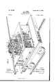
- Figure 1 is a perspective view of a coke-drawer embodying the invention.
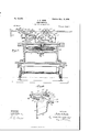
- Fig. 2 is a transverse vertical section taken through the center of the device.
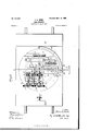
- Fig. 3 is a top plan view, partially broken away, showing the mechanism for operating the clutches.
- Fig. 4 is a detail perspective view of the clutch-operating mechanism and a portion of the shafts on which the clutch-sleeves are mounted.
- Fig. 5 is top plan view of the entire device. f
- the numeral 1 designates an under platform, where the power is attached, and extending therethrough is an operating-shaft 2,mounted in suitable bearings and adapted to be actuated by any preferred form of motive power.
- the said shaft 2 has a pinion 3 secured adbearing-bracket 5, and meshing with the npper side thereof is a vertically-disposed bevel gear-wheel 6, Fig. 1, extending through a slot in a rotatable table 7 and mounted upon a shaft 8, having bearing at its opposite endsin vjournal-supports 9 and 10.
- a guard-standard 26, Figs. 1 and 3 which is suitably braced and stands adjacent to the outer face of the pinion 25 for a purpose, being held in this position, as stated, by braces,
- a bolster 28, Fig. 4 is mounted, and thereto is pivotally connected a double yoke 29, having its opposite ends bifurcated and supplied with inwardlyprojecting pins 30, which engage grooves 3l in the clutch-sleeves 1S and 22.
- an arm 32 extends inwardly in a horizontal plane from the j ournal-support l0 and over the upper part of a depressed portion of the said yoke, and said arm has seated thereon a pivot-pin, which passes into the said yoke.
- a linkrod is secured, and at its opposite end passes through a slot 34, Fig. 2, in the journal-support 14 and is'attached tothe short arm of a bell-crank lever 35, also mounted in said slot, and to the longer arm of the said bell-crank lever a second link-rod 36, Fig. 3, is connected at its rear end and at theforward end attached to an operating-lever37, mounted in one of the slots 3S of a standard 39, havin g upper segmental toothed edges,and in connection with the said lever 37 is a spring-actuated gripping-dog 44, Figs.
- a second lever 4l is also mounted and operates a shaft 42, which has a crank-arm 43 thereon, situated to one side of the said standard.
- the lever 4l is also supplied with a spring-actuated dog 44, Fig. l, adapted to engage one of the adjacent segmental toothed edges of the standard to hold the said lever and the parts which it controls in the position desired.
- Adjacent to the standard is a bed 45, having a slot 4G, Fig.
- the said adj Listing-seat comprises a shank 49, which extends rearwardly and is pivotally supported between two lugs 50, disposed at the rear of the bed 45.
- the front portion of the said seat is in the form of an extended bed 5l, Fig. 2, having a front downwardly-curved edge 52, and in rear of said edge are upwardlyprojecting guides 53, having front and rear inner beveled ends, and across the top of the front portions of the said guides extends a keeper 54.
- the said seat 48 supports and controls the elevation of a scraper 55, consisting of an elongated bar with serrations or teeth 5G on the lower edge thereof.
- the said teeth 56 engage the teeth of the pinion 25, and by the operation of the said pinion the scraper is drawn inwardly or moved outwardly through its seat, and by operating the lever 4l the said seat may be raised or lowered in accordance with the elevation of the coke to be engaged by the outer end'of the scraper.
- a head 57 Secured on the outer end of the said scraper is a head 57, simulating a hoe or drag and' having a front lowerbeveled portion 58 to offer as little resist-ance as possible in the forward movement of the scraper-and the head against the coke, and also to reduce the lower edge of the said head in order that a proper penetration between the pieces of coke may be accomplished.
- the table 7 is rotatable, as previously set forth, so that the position of the scraper may be changed relatively to the coke in the oven, and the said table is adapted to be turnedby hand.
- a curved holding-bar 59 is secured, which extends around the said table a suitable distance and has on the upper surface, near opposite ends thereof, ratchet-teeth 60, which are reversely arranged and engaged by elongated dogs (il, which are movable through a keeper 62, at-
- the dogs Gl are pivotally attached to a lever G4, and the latter is movably connected to the said support 63 and may have a suitable locking device connected thereto for holding it inade-4 sired adjustment, as well as other appurtenances to facilitate its operation.
- the dogs 6l also have connected thereto operating-arms 65, by means of which they may be disconnected from the teeth GO when it is desired to materially shift the table 7. Under ordinary conditions, however, the said table 7 may be slightly moved by operating the lever 64 and changing the position of the scraper on the surface of the coke.
- the clutch-sleeves 1S and 22 are actuated by the lever 37, through the bell-crank lever 35 and the yoke 29, to either start or stop the mechanism.
- the device as an entirety will be mounted on a truck 6G, movable upon a track of preferred gage.
- the lower part of the machine is preferably constructedof wood,while the mechanism exposed above is of metal, and the several wheels and other devices can be varied indimension to suit the work or application of the machine or for any other purpose. It Will also be understood that the scraper may be elongated or shortened and the gear changed to suit the work and conditions of the coke-yard.
- a coke-drawer In a coke-drawer, the combination of a rotatable table, supporting gears and pinions and the shafts on which the same are mounted journaled on said table, a plurality of said pinions having clutch collars, adjustable clutch-sleeves for engaging said pinions with vtheir shafts, a pivoted double yoke for operating said clutch-sleeves, a lever connected to said yoke, a scraper controlled in its movements by the change of position of the clutchsleeves, and a double gear and its actuatingpinion for actuatingthe gearing carried by said table, all substantially as described.
Landscapes
- Chemical & Material Sciences (AREA)
- Engineering & Computer Science (AREA)
- Materials Engineering (AREA)
- Oil, Petroleum & Natural Gas (AREA)
- Organic Chemistry (AREA)
- Mechanical Operated Clutches (AREA)
Description
Patented Mar. 2|, |899. A. HEBB.v y GUKEADRAwEn.
` '(Appucmon mea Aug. 12, 1897.)
(No Model.)
No. 62|,663. vPatented Mar. 2|, |899.
J. A. HEBB. v
COKE DRAWER.
(Application med Aug'. 12, 1897., (Nb Model.) 4 Sheets-Sheet 2.
WTNESSE INVENTOH ,9/ y 7% 70m/ZM@ l -0 r I Aff/@MM N0. 62|,663. Patllled Mal'. 2||899. J. A. HEBB.
COKE DRAWER.
(Application led Aug'.A 12, 1897.)
(Ns Model.)
Mmm@
anmmw,
me Nonms PETERS co, PHoTouTno.. WASHINGTON. uy c.
No. 62l,663.
J. A. HEBB.
coKE DRAWER.
(Application led Aug. 12, 1897.)
Patented Mar. 2|, |899.
(No Model.)
4 sheet-*sheet 4.
@ff-Lf INVENTOR TN: nomma Pneus ou.. wmaurno., msmncmn, v c.
' UNITED STATES PATENT EEicE.
JOHN A. HEBB, OF BROVVNSFIELD, PENNSYLVANIA.
- COKE-DRAWER.
SPECIFICATION formingpart of Letters Patent N0. 621,663, dated March 21, 1899. Application filed August 12, 1897. Serial No. 648,064. (No model.)
T all whom t may concern:
Be it known that I, JOHN A. HEBB, of
,Brownsiielch in the county of Fayette and State of Pennsylvania, have invented certain new and useful Improvements in Coke-Drawers; and I do hereby declare the following toV be a full, clear, and exact description of the invention, such as will enable others skilled inthe art to which it appertains to make and use the same.
This invention relates to coke-drawers for use in connection with beehive and other ovens; and it consists, essentially, of a rotatable table-supporting operating mechanism including a reciprocating scraper that is positively actuated to engage and draw or drag the coke from one point to another.
The invention further consists of the details of construction and arrangement of the several parts, which will be more fully hereinafter described and claimed.
The object of the invention is to provide a drawer that may be operated in connection with or by steam, compressed air, or electricity and one that will work over the top of the coke in the same manner that it is workedv by hand, the parts being simple and effective in their construction and operation, strong and durable, easily and readily applied in operative position, and comparatively inexpensive in the cost of manufacture.
In the accompanying drawings, Figure 1 is a perspective view of a coke-drawer embodying the invention. Fig. 2 is a transverse vertical section taken through the center of the device. Fig. 3 is a top plan view, partially broken away, showing the mechanism for operating the clutches. Fig. 4 is a detail perspective view of the clutch-operating mechanism and a portion of the shafts on which the clutch-sleeves are mounted. Fig. 5 is top plan view of the entire device. f
Referring to the drawings, wherein similar numerals of reference are employed to indicate corresponding parts in the several views, the numeral 1 designates an under platform, where the power is attached, and extending therethrough is an operating-shaft 2,mounted in suitable bearings and adapted to be actuated by any preferred form of motive power. The said shaft 2 has a pinion 3 secured adbearing-bracket 5, and meshing with the npper side thereof is a vertically-disposed bevel gear-wheel 6, Fig. 1, extending through a slot in a rotatable table 7 and mounted upon a shaft 8, having bearing at its opposite endsin vjournal-supports 9 and 10. On the end of the shaft S.o,pposite to that on ywhich the gear 6 is mounted a pinion 11 is secured and meshes with a second pinion 12, keyed to the outer end of a counter-shaft 13, Figs. 2 and 3, also having bearing in the journal-supportlO and in an inner similar lsupport 14. On the said counter-shaft 13 a smaller pinion 15 is loosely mounted and has a clutch-collar 16 attached thereto. The shaft 13 is also supplied with oppositely-disposed feathers 17 ,which are engaged by grooves in a clutch-sleeve 18, Fig. 4. In like manner the shaft 8, Fig. 3, has a loosely-mounted pinion 19 thereon, supplied with a clutch-collar 20, and adjacent to said pinion 19 the said shaft is also supplied with feathers 21, Fig. 4,which relatively coact with the grooves of a clutch-sleeve 22, and by means of the said clutch-collars and sleeves the motion of the shafts 8 and 13 may be transmitted to the pinions 15 and 19 when the said clutch-sleeves are operated to engage the clutch-collars in a manner which will be readily understood. 'The said clutch collars and sleeves are to be constructed to interlock in any of the well-known forms of such devices, and meshing with the said pinions 15 and 19 is a gear 23, Figs. 1 and 3, keyed to a shaft 24, also having bearing in the j ournal-v supports 10 and 14 above the level of the shafts 8 and 13, Fig. 2, and in a plane intermediate of the same. The end of the shaft 24, Fig. 2, extends beyond the journal-support 14, and thereon isalso keyedapinion 25,
and extending from the rotatable table 7 is a guard-standard 26, Figs. 1 and 3, which is suitably braced and stands adjacent to the outer face of the pinion 25 for a purpose, being held in this position, as stated, by braces,
IOO
which are connected to the journal-support 14 and also to a support 27, extending across a portion of the said table.
Near the journal-support l0 a bolster 28, Fig. 4, is mounted, and thereto is pivotally connected a double yoke 29, having its opposite ends bifurcated and supplied with inwardlyprojecting pins 30, which engage grooves 3l in the clutch-sleeves 1S and 22. To assist in the pivotal attachment of the said yoke 29, and also to sustain it in proper position relatively to the operatingtension brought to bear thereupon, an arm 32 extends inwardly in a horizontal plane from the j ournal-support l0 and over the upper part of a depressed portion of the said yoke, and said arm has seated thereon a pivot-pin, which passes into the said yoke. To the bottom of the said yoke, nearer one end thereof, a linkrod is secured, and at its opposite end passes through a slot 34, Fig. 2, in the journal-support 14 and is'attached tothe short arm of a bell-crank lever 35, also mounted in said slot, and to the longer arm of the said bell-crank lever a second link-rod 36, Fig. 3, is connected at its rear end and at theforward end attached to an operating-lever37, mounted in one of the slots 3S of a standard 39, havin g upper segmental toothed edges,and in connection with the said lever 37 is a spring-actuated gripping-dog 44, Figs. l and 3, adapted to take into the adjacent teeth of one of the said segmental edges to sustain the adjustment of the said lever. In the said standard 39 a second lever 4l is also mounted and operates a shaft 42, which has a crank-arm 43 thereon, situated to one side of the said standard. The lever 4l is also supplied with a spring-actuated dog 44, Fig. l, adapted to engage one of the adjacent segmental toothed edges of the standard to hold the said lever and the parts which it controls in the position desired. Adjacent to the standard is a bed 45, having a slot 4G, Fig. 2, therein, and through the said slot movably extends a connecting-link 47, pivotally attached at its upper end to the under side of a forward portion ot' an adjusting-seat 48. The said adj Listing-seat comprises a shank 49, which extends rearwardly and is pivotally supported between two lugs 50, disposed at the rear of the bed 45. The front portion of the said seat is in the form of an extended bed 5l, Fig. 2, having a front downwardly-curved edge 52, and in rear of said edge are upwardlyprojecting guides 53, having front and rear inner beveled ends, and across the top of the front portions of the said guides extends a keeper 54. The said seat 48 supports and controls the elevation of a scraper 55, consisting of an elongated bar with serrations or teeth 5G on the lower edge thereof. The said teeth 56 engage the teeth of the pinion 25, and by the operation of the said pinion the scraper is drawn inwardly or moved outwardly through its seat, and by operating the lever 4l the said seat may be raised or lowered in accordance with the elevation of the coke to be engaged by the outer end'of the scraper. Secured on the outer end of the said scraper is a head 57, simulating a hoe or drag and' having a front lowerbeveled portion 58 to offer as little resist-ance as possible in the forward movement of the scraper-and the head against the coke, and also to reduce the lower edge of the said head in order that a proper penetration between the pieces of coke may be accomplished.
The table 7 is rotatable, as previously set forth, so that the position of the scraper may be changed relatively to the coke in the oven, and the said table is adapted to be turnedby hand. On the upper platform or support, in which the said table is mounted, a curved holding-bar 59 is secured, which extends around the said table a suitable distance and has on the upper surface, near opposite ends thereof, ratchet-teeth 60, which are reversely arranged and engaged by elongated dogs (il, which are movable through a keeper 62, at-
tached to a support (53, and which acts to hold the said dogs downwardly and in engaging position with the said teeth 60. The dogs Gl are pivotally attached to a lever G4, and the latter is movably connected to the said support 63 and may have a suitable locking device connected thereto for holding it inade-4 sired adjustment, as well as other appurtenances to facilitate its operation. The dogs 6l also have connected thereto operating-arms 65, by means of which they may be disconnected from the teeth GO when it is desired to materially shift the table 7. Under ordinary conditions, however, the said table 7 may be slightly moved by operating the lever 64 and changing the position of the scraper on the surface of the coke.
IOO
The clutch-sleeves 1S and 22 are actuated by the lever 37, through the bell-crank lever 35 and the yoke 29, to either start or stop the mechanism.
The device as an entirety will be mounted on a truck 6G, movable upon a track of preferred gage.
The lower part of the machine is preferably constructedof wood,while the mechanism exposed above is of metal, and the several wheels and other devices can be varied indimension to suit the work or application of the machine or for any other purpose. It Will also be understood that the scraper may be elongated or shortened and the gear changed to suit the work and conditions of the coke-yard.
By the arrangement of the clutches as set forth means are provided for changing the stroke of the scraper from an outward to an inward direction, and to accomplish this end the lever 37 is operated to first throw one clutch in connection with its clutch-collar and the other outward from engagement with its clutch-collar Without reversing the main driving mechanism.
It is obviously apparent that many minor IIO rangement of the several parts may be made and substituted for those shown and described withoutin the least departing from the nature orspirit of the invention.
Having thus described the invention,what is claimed as new isl. In -a coke-drawer, the combination of a rotatable table, an actuating-lever and dogs for operating said table and supported thereby, a segmental `rack-bar engaged by said dogs, a vertically-adjustable reciprocating scraper supported by said table, and mechanism carried by said table for operating said scraper, substantially as described.
2. In a coke-drawer, the combination of a driVing-shaftcarrying a pinion, a double-gear l gears, and pinions mounted on and movable with said table, clutch mechanisms for saidl gearsand shafts, a reciprocating scraper operated by said gears, one of which is in direct mesh with said scraper, an adjustable seat support-ing said scraper and adapting it to be adjusted vertically, mechanism carried by the rotatable table for adj Listing it on its vertical pivot,and mechanism also carried by said table for controlling theseat and clutches, v
substantially as described.
4:. In a coke-drawer, the combination of a rotatable table, supporting gears and pinions and the shafts on which the same are mounted journaled on said table, a plurality of said pinions having clutch collars, adjustable clutch-sleeves for engaging said pinions with vtheir shafts, a pivoted double yoke for operating said clutch-sleeves, a lever connected to said yoke, a scraper controlled in its movements by the change of position of the clutchsleeves, and a double gear and its actuatingpinion for actuatingthe gearing carried by said table, all substantially as described.
In testimony whereof;` I have signed this specification inthe presence of two subscribing witnesses.
' AJOHN A. HERB. Witnesses:
FRANK Y. SPRINGER,
W. Il. KENNEDY.
Publications (1)
| Publication Number | Publication Date |
|---|---|
| US621663A true US621663A (en) | 1899-03-21 |
Family
ID=2690270
Family Applications (1)
| Application Number | Title | Priority Date | Filing Date |
|---|---|---|---|
| US621663D Expired - Lifetime US621663A (en) | Coke-drawer |
Country Status (1)
| Country | Link |
|---|---|
| US (1) | US621663A (en) |
-
0
- US US621663D patent/US621663A/en not_active Expired - Lifetime
Similar Documents
| Publication | Publication Date | Title |
|---|---|---|
| US621663A (en) | Coke-drawer | |
| US569887A (en) | Scraper | |
| US1113431A (en) | Agricultural apparatus. | |
| US727790A (en) | Coke-drawing machine. | |
| US1164518A (en) | Disk cultivator. | |
| US1196088A (en) | Opebating hbams eos | |
| US1480529A (en) | Tiltable vehicle stand | |
| US765090A (en) | Beet-harvester. | |
| US1040488A (en) | Plowing mechanism. | |
| US1218564A (en) | Frictional gearing. | |
| US773505A (en) | Manure-spreader. | |
| US904232A (en) | Grain-drill. | |
| US916960A (en) | Cotton-chopper. | |
| US727943A (en) | Coke-drawing machine. | |
| US1177039A (en) | Plowing-machine. | |
| US339864A (en) | Log-turner | |
| US640812A (en) | Ditching-machine. | |
| US661028A (en) | Clod-crusher. | |
| US489707A (en) | Wheeled excavator and carrier | |
| US1315666A (en) | Sough | |
| US749058A (en) | Coke-drawing machine | |
| US1073636A (en) | Mechanical plow-lift. | |
| US216735A (en) | Improvement in seeding-machines | |
| US1159268A (en) | Automatic-disengaging motor-plow. | |
| US1078842A (en) | Excavator. |