US6215604B1 - Optical lens capable of being easily fitted in cavity of lens holder with high positioning accuracy - Google Patents
Optical lens capable of being easily fitted in cavity of lens holder with high positioning accuracy Download PDFInfo
- Publication number
- US6215604B1 US6215604B1 US09/491,820 US49182000A US6215604B1 US 6215604 B1 US6215604 B1 US 6215604B1 US 49182000 A US49182000 A US 49182000A US 6215604 B1 US6215604 B1 US 6215604B1
- Authority
- US
- United States
- Prior art keywords
- lens
- cavity
- optical lens
- optical
- lens holder
- Prior art date
- Legal status (The legal status is an assumption and is not a legal conclusion. Google has not performed a legal analysis and makes no representation as to the accuracy of the status listed.)
- Expired - Fee Related
Links
Images


Classifications
-
- G—PHYSICS
- G02—OPTICS
- G02B—OPTICAL ELEMENTS, SYSTEMS OR APPARATUS
- G02B7/00—Mountings, adjusting means, or light-tight connections, for optical elements
- G02B7/02—Mountings, adjusting means, or light-tight connections, for optical elements for lenses
Definitions
- This invention relates to an optical lens which is held by a lens holder, particularly, relates to an optical lens which is capable of being easily fitted in a cavity of a lens holder with high positioning accuracy.
- an electronic data processing equipment such as a personal computer is connected to various peripheral devices which include a memory device.
- a memory device an optical disk memory device can be used.
- the optical disc memory device is, for example, a CD-R drive which can write/read data to/From a CD-R (compact disc recordable) as a recording medium by using a laser beam.
- the CD-R is a write-once optical disc that allows additional writing many times but does not allow erasing data recorded thereon.
- the CD-R can be used for a CD-ROM or a CD-DA (audio CD) because the data recorded thereon can be read by a normal CD-ROM drive.
- the optical disc memory device has an optical pickup to apply the laser beam on a surface of the recording medium and to detect the reflection from the surface.
- the optical pickup includes a laser beam source for emitting the laser beam, an object or optical lens for gathering the laser beam from the laser beam source on the surface of the recording medium, and a lens holder for holding the object lens.
- the lens holder has a through-hole for passing the laser beam through therein.
- a part of the through-hole serves as a cavity for receiving the object lens.
- the cavity is larger than the other part of the through-hole in inner diameter.
- the object lens is fitted in the cavity of the lens holder by a running (or free) fit method or an interference fit method.
- the running fit method there is a problem that it is difficult to put the object lens in a desired position of the cavity. In other wards, the running fit method can not position the object lens to the lens holder with high positioning accuracy. This is because there is a gap between a peripheral or outer side surface of the object lens and an inner side surface of the cavity. When the object lens is not in the desired position, it is impossible to obtain desired optical characteristics for the optical pickup.
- the interference fit method does not have such a problem as the running fit method.
- the interference fit method has another problem that it is necessary to press the object lens with large pressing force in the cavity. The large pressing force deforms the object lens and deteriorates optical characteristics for the optical pickup.
- an optical lens is fitted in a cavity of a lens holder and fixed thereto.
- the cavity has a predetermined inside diameter.
- the optical lens comprises a lens body having a peripheral surface and an outside diameter smaller than the predetermined inside diameter.
- a projection is formed on the peripheral surface and protrudes to a radial direction for interfering with a fitting of the lens body in the cavity without resistance.
- a lens holder is for holding the above mentioned optical lens.
- the lens holder comprises a first section having the cavity with a trench which is for partially receiving the projection when the optical lens is fitted in the cavity.
- a second section is continuous with the first section and has a hole which is continuous with the cavity and which has an inside diameter smaller than the outside diameter of the lens body.
- an optical lens has a lens body which has a peripheral surface and an outer diameter.
- a projection is formed on the peripheral surface and protrudes in a radial direction of the optical lens.
- a lens holder has a cavity which has an inner diameter larger than the outer diameter to receive the lens body.
- a method of fixing of the optical lens to the lens holder comprises the steps of placing the optical lens in front of the cavity, and pressing the optical lens in the cavity while deforming the projection thereby.
- FIGS. 1A and 1B are side view and rear view of a conventional optical lens, respectively;
- FIGS. 2A and 2B are sectional view and front view of a conventional lens holder, respectively;
- FIGS. 3A and 3B are sectional view and front view of the lens holder of FIGS. 2A and 2B with the optical lens of FIGS. 1A and 1B;
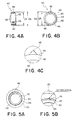
- FIGS. 4A and 4B are side view and rear view of an optical lens according to a preferred embodiment of this invention, respectively;
- FIG. 4C is a partial enlarged view in a dashed-line circle of FIG. 4B;
- FIG. 5A is a front view of the lens holder of FIGS. 2A-2B with the optical lens of FIGS. 4A-4C;
- FIG. 5B is a partial enlarged view of a region enclosed in a dashed-line circle of FIG. 5A;
- FIGS. 6A and 6B are sectional view and front view of a lens holder suitable for the optical lens of FIGS. 4A-4C, respectively;
- FIG. 7A is a front view of the lens holder of FIGS. 6A-6B with the optical lens of FIGS. 4A-4C;
- FIG. 7B is a partial enlarged view of a region enclosed in a dashed-line circle of FIG. 7 A.
- FIGS. 1A and 1B are side view and rear view of the optical lens 10 , respectively.
- the optical lens 10 has a solid cylindrical part 12 with an outside diameter D 1 and a spherical part 14 which is integrally formed on the solid cylindrical part 12 .
- the optical lens 10 is held by a conventional lens holder as shown in FIGS. 2A and 2B.
- FIGS. 2A and 2B are sectional view and front view of the lens holder 20 , respectively.
- the lens holder 20 has a hollow cylindrical shape with a through-hole 22 .
- a front part of the through-hole 22 serves as a receiving cavity 24 for receiving the optical lens 10 .
- the receiving cavity 24 has an inner diameter D 2 which is larger than that D 3 of the other part (or a rear part) 26 of the through-hole 22 .
- the optical lens 10 is fitted in the receiving cavity 24 of the lens holder 20 with a running or free fit method or an interference fit method.
- the receiving cavity 24 is formed so that the inner diameter D 2 is slightly larger than the outside diameter D 1 of the optical lens 10 . Consequently, the optical lens 10 can be fitted in the receiving cavity 24 without frictional resistance from the lens holder 20 .
- the optical lens 10 fitted in the cavity 24 finally comes in contact with a step between the receiving cavity 24 and the other part 26 because the inner diameter D 3 is smaller than the outside diameter D 1 . Then, the optical lens 10 is fixed to the lens holder 20 by, for example, an adhesive.
- the optical lens 10 can be easily fitted in the cavity 24 according to the running fit method.
- it is difficult to put the optical lens 10 in a desired position of the cavity 24 according to the running fit method because there is a gap between the optical lens 10 and the lens holder 20 as illustrated in FIGS. 3A and 3B.
- the running fit method has low positioning accuracy of the optical lens into the cavity of the lens holder 20 .
- the optical lens 10 When the optical axis of the optical lens 10 does not coincide with the central axis of the lens holder 20 , a laser beam travelling on the central axis of the lens holder 20 can not travel on the optical axis of the optical lens 10 . As a result, the optical lens 10 held by the lens holder 20 can not provide desired optical characteristics.
- the receiving cavity 24 is formed so that the inner diameter D 2 is slightly smaller than the outside diameter D 1 .
- the optical lens can not be fitted without frictional resistance from an inner side surface of the lens holder. Consequently, fitting the optical lens 10 in the receiving cavity 24 , it must be pressed with large pressing force. The large pressing force deforms the optical lens. The deformed optical lens 10 can not provide desired optical characteristics.
- the conventional optical lens 10 can not provide desired optical characteristics, when it is held by the lens holder 20 .
- FIGS. 4A and 4B are side view and rear view of the optical lens 40 , respectively.
- FIG. 4C is a partial enlarged view of a region enclosed in a dashed line circle of FIG. 4 B.
- the optical lens 40 comprises a solid cylindrical part 42 which has an outside diameter D 5 and a peripheral or outer side surface 44 .
- a solid spherical part 46 is integrally formed at a rear end of the solid cylindrical part 42 to form a lens body together with the solid cylindrical part 42 .
- Three projections 48 are integrally formed on the peripheral surface 44 at regular intervals. The projections 48 project in radial direction so as to be inscribed to a supposed circle 50 having a diameter D 6 .
- Each of the projections 48 has a triangular shape in section but it may have semicircular shape in section.
- the optical lens 40 is fitted in the cavity 24 of the lens holder 20 (see FIGS. 2 A and 2 B).
- the outside diameter D 5 is made so as to be slightly smaller than the inner diameter D 2 of the cavity 24 of the lens holder 20 .
- the projections 48 project so that the inner diameter D 6 of the supposed circle 50 is slightly larger than the inner diameter D 2 of the cavity 24 .
- the lens holder 20 is harder than the optical lens 40 . Compared with all area of the peripheral surface 44 , areas occupied by the projections 48 on the peripheral surface 44 is very small. Accordingly, the projections 48 is easily deformed by the lens holder 20 when the optical lens 40 is pressed into the cavity 24 as shown in FIG. 5B.
- a pressing force used for fitting the optical lens 40 in the cavity 24 is considerably smaller than that in an interference fit method. Therefore, the optical lens 40 is easily fitted in the cavity 24 when the optical lens 40 is pressed into the cavity 24 . Because the pressing force is small, the lens body is not deformed by the lens holder 20 in this event. Moreover, the projections 48 leads the lens body to a desired position in the cavity and keeps it in the desired position in this event. Therefore, it is easy to make an optical axis of the optical lens coincide with the central axis of the lens holder 20 with high positioning accuracy.
- the lens holder 60 has a hollow cylindrical shape with a through-hole 62 which includes a receiving cavity 64 like the cavity 24 of the conventional lens holder 20 .
- the lens holder 60 further has three trenches 66 formed in an inner wall which provide the cavity 64 .
- the trenches 66 extend along to a central axis of the lens holder 60 and are positioned at regular intervals in circumference direction and to correspond to the projections 48 of the optical lens 40 .
- the optical lens 40 is fitted in the cavity 64 in a state that the projections 48 are matched with the trenches 66 as shown in FIG. 7 A.
- the projections 48 partially enter the trenches 66 and are deformed as illustrated in FIG. 7 B.
- the projections 48 and the trenches 66 not only lead the lens body to a desired position in the cavity 64 and keeps it in the desired position but also prevent the lens body rotating around its optical axis.
- the combinations of the projections 48 and the trenches 66 are advantageous to an optical lens that its rotation changes its optical characteristics.
- the optical lens may have at least one projection.
- the lens holder may have at least one trench according to the number of the projection(s) of the optical lens.
- the optical lens may have another shape.
- the optical lens has two spherical part that is opposite to each other.
- the projection(s) may be formed on an edge of the lens body.
Landscapes
- Physics & Mathematics (AREA)
- General Physics & Mathematics (AREA)
- Optics & Photonics (AREA)
- Optical Head (AREA)
- Lens Barrels (AREA)
- Mounting And Adjusting Of Optical Elements (AREA)
Abstract
In an optical lens, a projection is formed on a peripheral surface of a lens body and protrudes to a radial direction of the lens body. The lens body has an outside diameter smaller than a predetermined inside diameter of a cavity of a lens holder. The projection interferes with a fitting of the lens body in the cavity without resistance. When the lens body is pressed in the cavity, the projection is deformed by the lens holder and follow the lens body fitting in the cavity.
Description
This invention relates to an optical lens which is held by a lens holder, particularly, relates to an optical lens which is capable of being easily fitted in a cavity of a lens holder with high positioning accuracy.
As well known, an electronic data processing equipment such as a personal computer is connected to various peripheral devices which include a memory device. As the memory device, an optical disk memory device can be used.
The optical disc memory device is, for example, a CD-R drive which can write/read data to/From a CD-R (compact disc recordable) as a recording medium by using a laser beam. The CD-R is a write-once optical disc that allows additional writing many times but does not allow erasing data recorded thereon. The CD-R can be used for a CD-ROM or a CD-DA (audio CD) because the data recorded thereon can be read by a normal CD-ROM drive.
The optical disc memory device has an optical pickup to apply the laser beam on a surface of the recording medium and to detect the reflection from the surface. The optical pickup includes a laser beam source for emitting the laser beam, an object or optical lens for gathering the laser beam from the laser beam source on the surface of the recording medium, and a lens holder for holding the object lens.
The lens holder has a through-hole for passing the laser beam through therein. A part of the through-hole serves as a cavity for receiving the object lens. Generally, the cavity is larger than the other part of the through-hole in inner diameter.
In a conventional technique, the object lens is fitted in the cavity of the lens holder by a running (or free) fit method or an interference fit method.
In the running fit method, there is a problem that it is difficult to put the object lens in a desired position of the cavity. In other wards, the running fit method can not position the object lens to the lens holder with high positioning accuracy. This is because there is a gap between a peripheral or outer side surface of the object lens and an inner side surface of the cavity. When the object lens is not in the desired position, it is impossible to obtain desired optical characteristics for the optical pickup.
On the other hand, the interference fit method does not have such a problem as the running fit method. However, the interference fit method has another problem that it is necessary to press the object lens with large pressing force in the cavity. The large pressing force deforms the object lens and deteriorates optical characteristics for the optical pickup.
It is therefore an object of this invention to provide an optical lens which is capable of being easily fitted in a cavity of a lens holder with high positioning accuracy.
It is another object of this invention to provide a lens holder which is suitable for the above mentioned optical lens.
Other object of this invention will become clear as the description proceeds.
On describing the gist of this invention, it is possible to understand that an optical lens is fitted in a cavity of a lens holder and fixed thereto. The cavity has a predetermined inside diameter.
According to the gist of this invention, the optical lens comprises a lens body having a peripheral surface and an outside diameter smaller than the predetermined inside diameter. A projection is formed on the peripheral surface and protrudes to a radial direction for interfering with a fitting of the lens body in the cavity without resistance.
According to another gist of this invention, a lens holder is for holding the above mentioned optical lens. The lens holder comprises a first section having the cavity with a trench which is for partially receiving the projection when the optical lens is fitted in the cavity. A second section is continuous with the first section and has a hole which is continuous with the cavity and which has an inside diameter smaller than the outside diameter of the lens body.
According to still another gist of this invention, an optical lens has a lens body which has a peripheral surface and an outer diameter. A projection is formed on the peripheral surface and protrudes in a radial direction of the optical lens. A lens holder has a cavity which has an inner diameter larger than the outer diameter to receive the lens body. A method of fixing of the optical lens to the lens holder comprises the steps of placing the optical lens in front of the cavity, and pressing the optical lens in the cavity while deforming the projection thereby.
FIGS. 1A and 1B are side view and rear view of a conventional optical lens, respectively;
FIGS. 2A and 2B are sectional view and front view of a conventional lens holder, respectively;
FIGS. 3A and 3B are sectional view and front view of the lens holder of FIGS. 2A and 2B with the optical lens of FIGS. 1A and 1B;
FIGS. 4A and 4B are side view and rear view of an optical lens according to a preferred embodiment of this invention, respectively;
FIG. 4C is a partial enlarged view in a dashed-line circle of FIG. 4B;
FIG. 5A is a front view of the lens holder of FIGS. 2A-2B with the optical lens of FIGS. 4A-4C;
FIG. 5B is a partial enlarged view of a region enclosed in a dashed-line circle of FIG. 5A;
FIGS. 6A and 6B are sectional view and front view of a lens holder suitable for the optical lens of FIGS. 4A-4C, respectively;
FIG. 7A is a front view of the lens holder of FIGS. 6A-6B with the optical lens of FIGS. 4A-4C; and
FIG. 7B is a partial enlarged view of a region enclosed in a dashed-line circle of FIG. 7A.
Referring to FIGS. 1A and 1B, description will be at first directed to a conventional optical lens for a better understanding of this invention.
FIGS. 1A and 1B are side view and rear view of the optical lens 10, respectively. As shown in FIGS. 1A and 1B, the optical lens 10 has a solid cylindrical part 12 with an outside diameter D1 and a spherical part 14 which is integrally formed on the solid cylindrical part 12. The optical lens 10 is held by a conventional lens holder as shown in FIGS. 2A and 2B.
FIGS. 2A and 2B are sectional view and front view of the lens holder 20, respectively. As shown in FIGS. 2A and 2B, the lens holder 20 has a hollow cylindrical shape with a through-hole 22. A front part of the through-hole 22 serves as a receiving cavity 24 for receiving the optical lens 10. The receiving cavity 24 has an inner diameter D2 which is larger than that D3 of the other part (or a rear part) 26 of the through-hole 22.
The optical lens 10 is fitted in the receiving cavity 24 of the lens holder 20 with a running or free fit method or an interference fit method.
For the running fit method, the receiving cavity 24 is formed so that the inner diameter D2 is slightly larger than the outside diameter D1 of the optical lens 10. Consequently, the optical lens 10 can be fitted in the receiving cavity 24 without frictional resistance from the lens holder 20. The optical lens 10 fitted in the cavity 24 finally comes in contact with a step between the receiving cavity 24 and the other part 26 because the inner diameter D3 is smaller than the outside diameter D1. Then, the optical lens 10 is fixed to the lens holder 20 by, for example, an adhesive.
Thus, the optical lens 10 can be easily fitted in the cavity 24 according to the running fit method. However, it is difficult to put the optical lens 10 in a desired position of the cavity 24 according to the running fit method because there is a gap between the optical lens 10 and the lens holder 20 as illustrated in FIGS. 3A and 3B. Namely, the running fit method has low positioning accuracy of the optical lens into the cavity of the lens holder 20. Specifically, it is difficult to make an optical axis of the optical lens 10 coincide with a central axis of the lens holder 20 (or the through-hole 22). When the optical axis of the optical lens 10 does not coincide with the central axis of the lens holder 20, a laser beam travelling on the central axis of the lens holder 20 can not travel on the optical axis of the optical lens 10. As a result, the optical lens 10 held by the lens holder 20 can not provide desired optical characteristics.
On the other hand, for the interference fit method, the receiving cavity 24 is formed so that the inner diameter D2 is slightly smaller than the outside diameter D1. In this case, the optical lens can not be fitted without frictional resistance from an inner side surface of the lens holder. Consequently, fitting the optical lens 10 in the receiving cavity 24, it must be pressed with large pressing force. The large pressing force deforms the optical lens. The deformed optical lens 10 can not provide desired optical characteristics.
At any rate, the conventional optical lens 10 can not provide desired optical characteristics, when it is held by the lens holder 20.
Referring to FIGS. 4A-4C and 5A-5B, the description will proceed to an optical lens according to a preferred embodiment of this invention.
FIGS. 4A and 4B are side view and rear view of the optical lens 40, respectively. FIG. 4C is a partial enlarged view of a region enclosed in a dashed line circle of FIG. 4B.
As shown in FIGS. 4A through 4C, the optical lens 40 comprises a solid cylindrical part 42 which has an outside diameter D5 and a peripheral or outer side surface 44. A solid spherical part 46 is integrally formed at a rear end of the solid cylindrical part 42 to form a lens body together with the solid cylindrical part 42. Three projections 48 are integrally formed on the peripheral surface 44 at regular intervals. The projections 48 project in radial direction so as to be inscribed to a supposed circle 50 having a diameter D6. Each of the projections 48 has a triangular shape in section but it may have semicircular shape in section.
As shown in FIG. 5A, the optical lens 40 is fitted in the cavity 24 of the lens holder 20 (see FIGS. 2A and 2B). Herein, the outside diameter D5 is made so as to be slightly smaller than the inner diameter D2 of the cavity 24 of the lens holder 20. Furthermore, the projections 48 project so that the inner diameter D6 of the supposed circle 50 is slightly larger than the inner diameter D2 of the cavity 24. In addition, the lens holder 20 is harder than the optical lens 40. Compared with all area of the peripheral surface 44, areas occupied by the projections 48 on the peripheral surface 44 is very small. Accordingly, the projections 48 is easily deformed by the lens holder 20 when the optical lens 40 is pressed into the cavity 24 as shown in FIG. 5B. A pressing force used for fitting the optical lens 40 in the cavity 24 is considerably smaller than that in an interference fit method. Therefore, the optical lens 40 is easily fitted in the cavity 24 when the optical lens 40 is pressed into the cavity 24. Because the pressing force is small, the lens body is not deformed by the lens holder 20 in this event. Moreover, the projections 48 leads the lens body to a desired position in the cavity and keeps it in the desired position in this event. Therefore, it is easy to make an optical axis of the optical lens coincide with the central axis of the lens holder 20 with high positioning accuracy.
Referring to FIGS. 6A and 6B, the description will be made about a lens holder which is suitable for the optical lens 40.
In FIGS. 6A and 6B, the lens holder 60 has a hollow cylindrical shape with a through-hole 62 which includes a receiving cavity 64 like the cavity 24 of the conventional lens holder 20. The lens holder 60 further has three trenches 66 formed in an inner wall which provide the cavity 64. The trenches 66 extend along to a central axis of the lens holder 60 and are positioned at regular intervals in circumference direction and to correspond to the projections 48 of the optical lens 40.
The optical lens 40 is fitted in the cavity 64 in a state that the projections 48 are matched with the trenches 66 as shown in FIG. 7A. The projections 48 partially enter the trenches 66 and are deformed as illustrated in FIG. 7B. The projections 48 and the trenches 66 not only lead the lens body to a desired position in the cavity 64 and keeps it in the desired position but also prevent the lens body rotating around its optical axis. The combinations of the projections 48 and the trenches 66 are advantageous to an optical lens that its rotation changes its optical characteristics.
While this invention has thus for been described in conjunction with the preferred embodiment thereof, it will readily be possible for those skilled in the art to put this invention into practice in various other manners. For example, the optical lens may have at least one projection. The lens holder may have at least one trench according to the number of the projection(s) of the optical lens.
The optical lens may have another shape. For example, the optical lens has two spherical part that is opposite to each other. In this case, if the lens body has a small or no peripheral or outer side surface, the projection(s) may be formed on an edge of the lens body.
Claims (7)
1. An optical lens which is fitted in a cavity of a lens holder and fixed thereto, said cavity having a predetermined inside diameter, said optical lens comprising:
a lens body having an peripheral surface and an outside diameter smaller than the predetermined inside diameter, and
a projection formed on said peripheral surface and protruding to a radial direction for interfering with a fitting of said lens body in said cavity without resistance.
2. An optical lens as claimed in claim 1, wherein said projection is deformed by said lens holder when said lens body is pressed in said cavity.
3. An optical lens as claimed in claim 1, wherein said optical lens further comprises at least one additional projection formed on said peripheral surface.
4. An optical lens as claimed in claim 3, wherein the projections are positioned on said peripheral surface at regular intervals.
5. An optical lens as claimed in claim 4, wherein the number of said projections are three.
6. A lens holder for holding the optical lens claimed in claim 1, said lens holder comprising:
a first section having the cavity with a trench which is for partially receiving the projection when the optical lens is fitted in the cavity, and
a second section being continuous with said first section and having a hole which has an inside diameter smaller than the outside diameter of said lens body.
7. A method of fixing of an optical lens to a lens holder, said optical lens having a lens body which has a peripheral surface and an outer diameter, and a projection which is formed on the peripheral surface and which protrudes in a radial direction of said optical lens, said lens holder having a cavity which has an inner diameter larger than the outer diameter to receive the lens body, comprising the steps of:
placing said optical lens in front of said cavity, and
pressing said optical lens in said cavity while deforming said projection thereby.
Applications Claiming Priority (2)
| Application Number | Priority Date | Filing Date | Title |
|---|---|---|---|
| JP11019812A JP2000215495A (en) | 1999-01-28 | 1999-01-28 | Optical lens and lens holder |
| JP11-019812 | 1999-01-28 |
Publications (1)
| Publication Number | Publication Date |
|---|---|
| US6215604B1 true US6215604B1 (en) | 2001-04-10 |
Family
ID=12009753
Family Applications (1)
| Application Number | Title | Priority Date | Filing Date |
|---|---|---|---|
| US09/491,820 Expired - Fee Related US6215604B1 (en) | 1999-01-28 | 2000-01-26 | Optical lens capable of being easily fitted in cavity of lens holder with high positioning accuracy |
Country Status (3)
| Country | Link |
|---|---|
| US (1) | US6215604B1 (en) |
| EP (1) | EP1024386A1 (en) |
| JP (1) | JP2000215495A (en) |
Cited By (15)
| Publication number | Priority date | Publication date | Assignee | Title |
|---|---|---|---|---|
| US6359740B1 (en) * | 2000-09-20 | 2002-03-19 | San Hua Tien Precision Circuit Co., Ltd. | Image capturing device |
| US20020097453A1 (en) * | 2001-01-23 | 2002-07-25 | Wen-Ching Chen | CCD and CMOS image pickup module |
| US20040165288A1 (en) * | 2003-02-21 | 2004-08-26 | Sharp Kabushiki Kaisha | Optical pickup lens, and optical pickup unit comprising the same |
| US6888690B2 (en) * | 2003-01-07 | 2005-05-03 | Pentax Corporation | Hot crimping structure and method for fixing a lens to a lens frame, and hot crimping tool therefor |
| US20060139774A1 (en) * | 2004-12-29 | 2006-06-29 | Stefan Pfnuer | Lens mount assembly for optical components |
| US20070291379A1 (en) * | 2004-10-02 | 2007-12-20 | Trumpf Werkzeugmaschinen Gmbh + Co. Kg | Laser machine monitoring |
| CN100370300C (en) * | 2005-03-18 | 2008-02-20 | 富士能株式会社 | Plastic lens and method and apparatus for manufacturing same |
| US20100053781A1 (en) * | 2008-08-29 | 2010-03-04 | Hon Hai Precision Industry Co., Ltd. | Lens module and camera module having same |
| US20100124415A1 (en) * | 2008-11-20 | 2010-05-20 | Shenzhen Futaihong Precision Industry Co., Ltd. | Dust protector for camera module and portable electronic device using the same |
| US20110299377A1 (en) * | 2010-06-07 | 2011-12-08 | Hoya Corporation | Lens and optical pick-up |
| US8284506B2 (en) | 2008-10-21 | 2012-10-09 | Gentex Corporation | Apparatus and method for making and assembling a multi-lens optical device |
| CN103955044A (en) * | 2014-03-31 | 2014-07-30 | 苏州佳世达光电有限公司 | Electronic device, camera module and assembly method thereof |
| US20180354079A1 (en) * | 2017-06-08 | 2018-12-13 | Trumpf Laser Gmbh | Protective glass with transponder and installation aid and associated laser tool |
| US11448731B2 (en) | 2019-08-30 | 2022-09-20 | Banner Engineering Corp. | Triangulation sensor with a first metal lens barrel disposed in a first barrel mounting channel |
| US11467473B2 (en) * | 2017-11-10 | 2022-10-11 | Huawei Technologies Co., Ltd. | Lens assembly, camera module, and terminal |
Families Citing this family (4)
| Publication number | Priority date | Publication date | Assignee | Title |
|---|---|---|---|---|
| EP2209034B1 (en) * | 2009-01-14 | 2013-02-13 | Qioptiq Photonics GmbH & Co. KG | Optical component |
| JP6024941B2 (en) * | 2012-01-20 | 2016-11-16 | 株式会社富士通ゼネラル | Lens fixing mechanism and camera device having the same |
| KR20140053570A (en) * | 2012-10-26 | 2014-05-08 | 삼성전기주식회사 | Lens barrel for camera |
| CN110161594A (en) * | 2019-06-21 | 2019-08-23 | 中山联合光电科技股份有限公司 | A kind of structure for processing and film plating lantern ring |
Citations (5)
| Publication number | Priority date | Publication date | Assignee | Title |
|---|---|---|---|---|
| US4662717A (en) | 1983-02-19 | 1987-05-05 | Olympus Optical Company Ltd. | Lens and lens holding devices |
| US5024509A (en) | 1989-03-14 | 1991-06-18 | Konica Corporation | Structural combination of plastic lenses |
| US5396487A (en) | 1989-09-19 | 1995-03-07 | Asahi Kogaku Kogyo Kabushiki Kaisha | Structure for holding an optical article |
| US5608579A (en) | 1994-03-30 | 1997-03-04 | Sony Corporation | Projection TV set apparatus |
| DE19623418A1 (en) | 1996-06-12 | 1997-12-18 | Zeiss Carl Jena Gmbh | Lens group self-centering holder |
-
1999
- 1999-01-28 JP JP11019812A patent/JP2000215495A/en not_active Withdrawn
-
2000
- 2000-01-26 US US09/491,820 patent/US6215604B1/en not_active Expired - Fee Related
- 2000-01-28 EP EP00300691A patent/EP1024386A1/en not_active Withdrawn
Patent Citations (5)
| Publication number | Priority date | Publication date | Assignee | Title |
|---|---|---|---|---|
| US4662717A (en) | 1983-02-19 | 1987-05-05 | Olympus Optical Company Ltd. | Lens and lens holding devices |
| US5024509A (en) | 1989-03-14 | 1991-06-18 | Konica Corporation | Structural combination of plastic lenses |
| US5396487A (en) | 1989-09-19 | 1995-03-07 | Asahi Kogaku Kogyo Kabushiki Kaisha | Structure for holding an optical article |
| US5608579A (en) | 1994-03-30 | 1997-03-04 | Sony Corporation | Projection TV set apparatus |
| DE19623418A1 (en) | 1996-06-12 | 1997-12-18 | Zeiss Carl Jena Gmbh | Lens group self-centering holder |
Cited By (28)
| Publication number | Priority date | Publication date | Assignee | Title |
|---|---|---|---|---|
| US6359740B1 (en) * | 2000-09-20 | 2002-03-19 | San Hua Tien Precision Circuit Co., Ltd. | Image capturing device |
| US20020097453A1 (en) * | 2001-01-23 | 2002-07-25 | Wen-Ching Chen | CCD and CMOS image pickup module |
| US6900913B2 (en) * | 2001-01-23 | 2005-05-31 | Wen-Ching Chen | Image pickup module |
| US6888690B2 (en) * | 2003-01-07 | 2005-05-03 | Pentax Corporation | Hot crimping structure and method for fixing a lens to a lens frame, and hot crimping tool therefor |
| US7099090B2 (en) * | 2003-02-21 | 2006-08-29 | Sharp Kabushiki Kaisha | Optical pickup lens comprising a lens and a lens holder which have marks to easily mount the lens on the lens holder at a predetermined angle in the direction of rotation of the lens, and optical pickup unit comprising the optical pickup lens |
| US20040165288A1 (en) * | 2003-02-21 | 2004-08-26 | Sharp Kabushiki Kaisha | Optical pickup lens, and optical pickup unit comprising the same |
| US7875830B2 (en) * | 2004-10-02 | 2011-01-25 | Trumpf Werkzeugmaschinen Gmbh + Co. Kg | Laser machine monitoring |
| US20070291379A1 (en) * | 2004-10-02 | 2007-12-20 | Trumpf Werkzeugmaschinen Gmbh + Co. Kg | Laser machine monitoring |
| US8445815B2 (en) | 2004-10-02 | 2013-05-21 | Trumpf Werkzeugmaschinen Gmbh + Co. Kg | Laser machine monitoring |
| US20110100968A1 (en) * | 2004-10-02 | 2011-05-05 | Trumpf Werkzeugmaschinen Gmbh + Co. Kg | Laser machine monitoring |
| WO2006071789A3 (en) * | 2004-12-29 | 2006-09-21 | Finisar Corp | Lens mount assembly for optical components |
| US7372647B2 (en) * | 2004-12-29 | 2008-05-13 | Finisar Corporation | Lens mount assembly for optical components |
| US20060139774A1 (en) * | 2004-12-29 | 2006-06-29 | Stefan Pfnuer | Lens mount assembly for optical components |
| WO2006071789A2 (en) * | 2004-12-29 | 2006-07-06 | Finisar Corporation | Lens mount assembly for optical components |
| CN100370300C (en) * | 2005-03-18 | 2008-02-20 | 富士能株式会社 | Plastic lens and method and apparatus for manufacturing same |
| US20100053781A1 (en) * | 2008-08-29 | 2010-03-04 | Hon Hai Precision Industry Co., Ltd. | Lens module and camera module having same |
| US7944632B2 (en) * | 2008-08-29 | 2011-05-17 | Hon Hai Precision Industry Co., Ltd. | Lens module and camera module having same |
| US8284506B2 (en) | 2008-10-21 | 2012-10-09 | Gentex Corporation | Apparatus and method for making and assembling a multi-lens optical device |
| US7967514B2 (en) * | 2008-11-20 | 2011-06-28 | Shenzhen Futaihong Precision Industry Co., Ltd. | Dust protector for camera module and portable electronic device using the same |
| US20100124415A1 (en) * | 2008-11-20 | 2010-05-20 | Shenzhen Futaihong Precision Industry Co., Ltd. | Dust protector for camera module and portable electronic device using the same |
| US20110299377A1 (en) * | 2010-06-07 | 2011-12-08 | Hoya Corporation | Lens and optical pick-up |
| US8305867B2 (en) * | 2010-06-07 | 2012-11-06 | Hoya Corporation | Lens and optical pick-up |
| CN103955044A (en) * | 2014-03-31 | 2014-07-30 | 苏州佳世达光电有限公司 | Electronic device, camera module and assembly method thereof |
| US20180354079A1 (en) * | 2017-06-08 | 2018-12-13 | Trumpf Laser Gmbh | Protective glass with transponder and installation aid and associated laser tool |
| US11247299B2 (en) * | 2017-06-08 | 2022-02-15 | Trumpf Laser Gmbh | Protective glass with transponder and installation aid and associated laser tool |
| US11467473B2 (en) * | 2017-11-10 | 2022-10-11 | Huawei Technologies Co., Ltd. | Lens assembly, camera module, and terminal |
| US11448731B2 (en) | 2019-08-30 | 2022-09-20 | Banner Engineering Corp. | Triangulation sensor with a first metal lens barrel disposed in a first barrel mounting channel |
| US11982763B2 (en) | 2019-08-30 | 2024-05-14 | Banner Engineering Corp. | Triangulation sensor comprising a first optical communication device defines a first translation plane and secured in a particular position along the plane |
Also Published As
| Publication number | Publication date |
|---|---|
| EP1024386A1 (en) | 2000-08-02 |
| JP2000215495A (en) | 2000-08-04 |
Similar Documents
| Publication | Publication Date | Title |
|---|---|---|
| US6215604B1 (en) | Optical lens capable of being easily fitted in cavity of lens holder with high positioning accuracy | |
| US4899330A (en) | Adaptor for mini CD | |
| US20070067786A1 (en) | Optical pickup device | |
| HU216997B (en) | Disk for recording signals and clamping construction for said disk | |
| JPH0362381A (en) | Optical disk cartridge with flexible recording medium | |
| CN101681659B (en) | Disk cartridge | |
| JPH08335351A (en) | Turntable | |
| EP1100085A2 (en) | Disk cartridge device | |
| US6817024B2 (en) | Method of fixing a laser diode to an optical base and optical pickup using the optical base | |
| US7002885B2 (en) | Method for determining an optical write power and an optical disc access system using the same | |
| EP1173848B1 (en) | Optical disk device | |
| KR100401779B1 (en) | Disc cartridge and disc apparatus | |
| US6304391B1 (en) | Object lens supporting unit capable of offsetting positional deviation of the lens caused by warp of suspension wire and method of assembling the unit | |
| JP3375238B2 (en) | Disk unit | |
| KR20000071841A (en) | Disk cartridge | |
| KR200245383Y1 (en) | compact disk case | |
| JP3298651B2 (en) | Information signal recording disk | |
| JP3755243B2 (en) | Optical pickup device and optical disk device | |
| JPS6323811Y2 (en) | ||
| JPH10154364A (en) | Simple mechanism for attaching drum to video recorder deck | |
| JPH0135353Y2 (en) | ||
| JPH0573772U (en) | Optical recording medium and electrical connector applied to this medium | |
| JP3510615B2 (en) | Disk cartridge | |
| KR200183602Y1 (en) | a device for displaying whether an optical disk is roaded or not | |
| JP3544393B2 (en) | Optical disk drive |
Legal Events
| Date | Code | Title | Description |
|---|---|---|---|
| AS | Assignment |
Owner name: MITSUMI ELECTRIC CO. LTD., JAPAN Free format text: ASSIGNMENT OF ASSIGNORS INTEREST;ASSIGNOR:HORI, KEN'ICHI;REEL/FRAME:010585/0036 Effective date: 20000124 |
|
| FEPP | Fee payment procedure |
Free format text: PAYOR NUMBER ASSIGNED (ORIGINAL EVENT CODE: ASPN); ENTITY STATUS OF PATENT OWNER: LARGE ENTITY |
|
| REMI | Maintenance fee reminder mailed | ||
| LAPS | Lapse for failure to pay maintenance fees | ||
| STCH | Information on status: patent discontinuation |
Free format text: PATENT EXPIRED DUE TO NONPAYMENT OF MAINTENANCE FEES UNDER 37 CFR 1.362 |
|
| FP | Lapsed due to failure to pay maintenance fee |
Effective date: 20050410 |