US621237A - Straw-stacker - Google Patents
Straw-stacker Download PDFInfo
- Publication number
- US621237A US621237A US621237DA US621237A US 621237 A US621237 A US 621237A US 621237D A US621237D A US 621237DA US 621237 A US621237 A US 621237A
- Authority
- US
- United States
- Prior art keywords
- pulley
- straw
- shaft
- elevating device
- delivering
- Prior art date
- Legal status (The legal status is an assumption and is not a legal conclusion. Google has not performed a legal analysis and makes no representation as to the accuracy of the status listed.)
- Expired - Lifetime
Links
- 230000003028 elevating effect Effects 0.000 description 34
- 239000010902 straw Substances 0.000 description 22
- 239000000969 carrier Substances 0.000 description 16
- 241000251169 Alopias vulpinus Species 0.000 description 11
- 238000010276 construction Methods 0.000 description 2
- 230000002452 interceptive effect Effects 0.000 description 2
Images

Classifications
-
- B—PERFORMING OPERATIONS; TRANSPORTING
- B65—CONVEYING; PACKING; STORING; HANDLING THIN OR FILAMENTARY MATERIAL
- B65G—TRANSPORT OR STORAGE DEVICES, e.g. CONVEYORS FOR LOADING OR TIPPING, SHOP CONVEYOR SYSTEMS OR PNEUMATIC TUBE CONVEYORS
- B65G37/00—Combinations of mechanical conveyors of the same kind, or of different kinds, of interest apart from their application in particular machines or use in particular manufacturing processes
Definitions
- My invention has relation to straw elevators and stackers adapted to be attached to threshing-machines; and it consists in the novel construction and arrangement of its parts, as hereinafter described.
- the object of the invention is to provide a horizontally-movable delivering device and a vertically-movable elevating device pivotally attached to the delivering device.
- the delivering device is provided with a suitable carrier, upon which the straw is deposited from the threshing-machine.
- the delivering device conveys the straw to the elevating device.
- the said elevating device is provided with two opposite carriers, the said carriers being adapted to move and elevate the straw and expel it from the upper end of the elevating device.
- a suitable means is provided whereby a rotary motion is transmitted to the various carriers in such manner as to not interfere with the adjusting or the movement of the delivering or elevating devices.
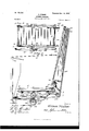
- Figure 1 is a side elevation of the invention, partly in section.
- Fig. 2 is a top plan view of the delivering device, with parts broken away; and
- Fig. 3 is a diagrammatic view showing the arrangement of the belts between the delivering and elevating devices.
- Fig. 4 is a side elevation of a modified form of the attachment, and
- Fig. 5 is a top plan view of the delivering device for the form as shown in Fig. 4.
- the delivering device consists of a frame 1, mounted on the table 2, the said table being attached to the rear end of the thresher.
- the fifth-wheel 3 is provided, and by means of the said fifth-wheel the frame 1 is adapted to revolve on the table 2.
- the rollers 4 and 4 are journaled, and the belt 5 passes around the said rollers, the said belt 5 being provided on its outer surface with the ordinary cross- Serial No. 688,131. (No model.)
- the elevating device is pivotally attached at the point '7 to the frame 1, and the beams 8 of the said device are provided at their lower ends with a roller 9 and at their upper ends with a roller 9, the carrier 10 passing around the said rollers.
- the lower roller 9 is located some distance below the roller 4, as shown in Fig. 1.
- the beams 11 are supported at their lower ends upon the beams S 8 by means of the brackets 12, as indicated by the dotted lines in Fig. 1.
- the said beams 11 are provided at their lower ends with a roller 13 and at their upper ends with a roller 13, the carrier 14 passing around the said rollers.
- the said beams 8 and 11 converge towardeach other at their upper ends, and the roller 13 is located above the roller 4, as shown in Fig. 1; also, the roller 13' is a trifle higher than the roller 9, as shown in the said figure.
- said beams 8 and 11 may be continuous or they may be provided at an intermediate point with a hinge-joint 15 and a suitable securing bolt or device 16.
- a hinge-joint 15 and a suitable securing bolt or device 16.
- a flexible connection 17 is attached at on end to the said elevating device, the said connection passing over the pulley 18, journaled in the thresher, and down and around a drum 19, the said drum 19 being provided with suitable ratchets adapted to engage the pawl 20.
- a handle 21 is provided, whereby the said drum 19 may be revolved, and in so doing the connection 17 is either lengthened or shortened and the elevating device correspondingly elevated or lowered, the pawl engaging the ratchets and maintaining the elevating device in the desired position.
- a horizontal shaft 22 is journaled in the table 2. The outer end of said shaft 22 is provided with a pulley-wheel 23, and the inner end of said shaft is provided with a bevel gear-wheel 24.
- the perpendicular shaft 25 is also journaled in the table 2, said shaft 25 being arranged concentrically with the fifth-wheel 3.
- the lower end of the shaft 25 is provided with a bevel gearwheel 26, which engages and meshes with the bevel gear-wheel 24.
- the upper end of the shaft 25 is provided with a ICO second bevel gear-wheel 27.
- the horizontal shaft 28 is journaled in the frame 1.
- the inner end of the said shaft 28 is provided with a bevel gear-wheel 29.
- the said gear-wheel 29 engages and meshes with the bevel gearwheel 27.
- the other end of the shaft 28 is provided with a suitable belt-pulley 30.
- the belt 31 passes around the pulley 32, the said pulley 32 being revolved by any suitable means.
- the belt 31 also passes around the pulley 23, and thereby transmits a revolving motion to the last said pulley. This motion is conveyed through the shaft 22 and the gearwheels 24 and to the perpendicular shaft 25, and from the said shaft 25, through the bevel gear-wheels 27 and 29, to the shaft 28 and the pulley 30.
- the belt 31 surrounds the pulley and a suitable pulley located on the shaft of the roller 4, and thus a rotary motion is transmitted to the said roller 4' and the carrier 5 is given a longitudinal movement.
- the shaft 25 concentric with the fifthwheel 3 it will be observed that the frame 1 may be turned or revolved on the table 2 while the carrier 5 is moving or while it is stationary and that in so moving the frame 1 there will be no binding upon any of the belts, shafts, 820.
- an open belt 33 passes around the pulley located on the shaft of the roller 4 and around the pulley 34, located on the pivotal rod 7 of the elevating device.
- the pulley 35 is arranged concentrically with the pulley 34, and the open belt 36 passes around the pulley 35 and the pulley 37, the said pulley 37 being fixed to the shaft of the roller 9, and thus it will be seen that the elevating device may be raised or lowered while the said belts and pulleys are in motion or while they are stationary without binding or other interference.
- a crossed belt 38 passes around the pulley 39, attached to the shaft of the roller 13, and thus it will be seen that by the said belts 38 and 36 a revolving motion is transmitted to the rollers 9 and 13, and thus the carriers 10 and 14 are moved longitudinally, the inner opposite faces of the carriers moving in the same outward direction.
- the device is operated as follows: The straw comingf rom the thresher is deposited upon the carrier 5.
- the said carrier carries the straw out and delivers it to the carriers 10 and 14.
- the said carriers elevate the straw and expel it at the upper end of the elevating device.
- the frame 1 may be revolved or turned horizontally, as above described, and the elevating device may be moved up or down Without interfering with any of the belts, &c.
- the elevating device may be moved up or down Without interfering with any of the belts, &c.
- the pulley 40 is fixed to the roller 9 of the beams 8 and the pulley 41 is fixed to the lower roller of the beams 11.
- the pulley 42 is fixed to the upper roller of the beams 8 and the loose pulley 43 is fixed to the shaft of the roller 4.
- the belt 44 passes around the pulley 45, which is attached to the shaft 28, then over the loose pulley 43, then under the pulley 41, the spring-actuated pulley 46 taking up any slack in the said belt, the belt passing over the said pulley 46, then over the pulley 42, then out and under the pulley 40 to the pulley 45.
- the lower belt of the elevating device is driven from both ends, and thus there is no possibility of the said belt buckling or refusing to operate.
- the parts may be also adjusted without interfering with the operation of the device.
- A11 attachment for threshing-machines consisting of a horizontally-movable delivering device adapted to receive the straw from the thresher, said delivering device comprising a longitudinally-movable carrier, the elevating device pivotally attached to the delivering device and adapted to receive the straw from the same, said elevating device comprising two longitudinally-movable carriers with their contiguous faces adapted to move in the same direction one of said carriers terminating above the outer end of the carrier of the delivering device and the other carrier terminating below the outer end of the carrier of the delivering device, and a suitable means for moving the said carriers, substantially as described.
- An attachment for a threshing-machine consisting cf a horizontally-movable delivering device adapted to receive the straw from the thresher, an elevating device pivotally attached thereto and comprising two longitudinally-movable carriers with their contiguous faces adapted to move in the same direction, said elevating-device being so 10-. cated as to receive the straw from the delivering device, substantially as described.
- An attachment for threshing-machines consisting of a horizontal delivering device adapted to receive the straw from the thresher, an adjustable elevating device adapted to convey the straw from said delivering device, said elevating device comprising two longitudinally-movable carriers having their contiguous faces adapted to move in the same direction, substantially as described.
- An attachment for threshing-machines consisting of a horizontally-movable delivering device adapted to receive the straw from the thresher, said delivering device comprising a longitudinally-movable carrier, means for transmitting motion from the threshingmachine to the delivering device, an elevating device pivotally attached to the delivering device and adapted to receive the straw therefrom, said elevating device comprising two longitudinally-movable carriers with their contiguous faces adapted tomove in the same direction and means for transmitting motion from the delivering device to the elevating device, substantially as described.
- An attachment for threshing-machines consisting of a horizontally-movable delivering device adapted to receive the straw. from the thresher, said delivering device comprising a longitudinally-movable carrier, means for transmitting motion from the threshingmachine to the delivering device, an elevating device pivotally attached to the delivering device and adapted to receive the straw therefrom, said elevating device comprising two longitudinally movable carriers with their contiguous faces adapted to move in the same direction and means for transmitting motion from the delivering device to the elevating device, substantially as described.
- An attachment for a threshing-machine consisting of a delivering device adapted to receive the straw from the thresher, a shaft journaled on the stationary part of the thresher below the delivering device, a vertical shaft connected to said horizontal shaft, a second horizontal shaft journaled in the delivering device and connected to the vertical shaft, a means for imparting rotary motion to said shafts, means for transmitting rotary motion from the said shafts to the longitudinally-movable carrier of the delivering device, an elevating device pivotally attached to the outer end of the delivering device, said elevating device comprising two movable car riers and a suitable means for transmitting motion from the delivering device to the carrier's of the elevating device, substantially as described.
- An attachment fora-threshing-machine consisting of a delivering device adapted to receive the straw from the thresher, an elevating device pivotally attached to the outer end of the delivering device, said elevating device comprising two longitudinally-movable carr'iers, a suitable means for transmitting motion to the moving parts of the deliv ering device, pulleys located on the elevating device and arranged-concentrically with the pivotal point of the same, a suitable means for transmitting rotary motion from the movable parts of the delivering device to said pulleys, and a suitable means for transmit ting rotary motion from said pulleys to the pulleys attached to the shaft or rollers of the longitudinally-movable carriers of the elevating device, substantially as described.
Landscapes
- Engineering & Computer Science (AREA)
- Mechanical Engineering (AREA)
- Threshing Machine Elements (AREA)
Description
No. 62!,237. Patented Mar -I4 I899 a. FISHER. STRAW STAGKER. (Application filed Aug. B 1898.)
(N0 Modei.)
2 SheetsSheet I.
gQeljTor-j 6%6233072/ 197a??? ih esscs mi "cams PETERS co. inm'n-umo" wAsmuo'ioN. n c
- GzZZw/zEsizei:
Nu. 62|,237. Patented Mar. 14, I899;
G. FISHER. Y
STRAW STABKER.
(Application filed Au e,- 1598. (No Model.)
2 Sheets-Shut 2.
mmim r 10 I 4" a v Nirn STATES GIDEON FISHER, OF LAPPS, PENNSYLVANIA.
STRAW-STACKER..
SPECIFICATION forming part of Letters Patent No. 621,237, dated March 14, 1899.
Application filed August 8, 1 8 9 8.
To aZZ whom it may concern:
Be it known that I, GIDEON FISHER, a citizen of the United States, residing at Lapps, in the countyof Lancaster and State of Pennsylvania, have invented certain new and useful Improvements in Straw-Stackers; and I do hereby declare the following to be a full, clear, and exact description of the invention, such as will enable others skilled in the art to which it appertains to make and use the same.
My invention has relation to straw elevators and stackers adapted to be attached to threshing-machines; and it consists in the novel construction and arrangement of its parts, as hereinafter described.
The object of the invention is to provide a horizontally-movable delivering device and a vertically-movable elevating device pivotally attached to the delivering device. The delivering device is provided with a suitable carrier, upon which the straw is deposited from the threshing-machine. The delivering device conveys the straw to the elevating device. The said elevating device is provided with two opposite carriers, the said carriers being adapted to move and elevate the straw and expel it from the upper end of the elevating device. A suitable means is provided whereby a rotary motion is transmitted to the various carriers in such manner as to not interfere with the adjusting or the movement of the delivering or elevating devices.
In the accompanying drawings, Figure 1 is a side elevation of the invention, partly in section. Fig. 2 is a top plan view of the delivering device, with parts broken away; and Fig. 3 is a diagrammatic view showing the arrangement of the belts between the delivering and elevating devices. Fig. 4 is a side elevation of a modified form of the attachment, and Fig. 5 is a top plan view of the delivering device for the form as shown in Fig. 4.
The delivering device consists of a frame 1, mounted on the table 2, the said table being attached to the rear end of the thresher. The fifth-wheel 3 is provided, and by means of the said fifth-wheel the frame 1 is adapted to revolve on the table 2. At the opposite ends of the table 2 the rollers 4 and 4 are journaled, and the belt 5 passes around the said rollers, the said belt 5 being provided on its outer surface with the ordinary cross- Serial No. 688,131. (No model.)
said beams 8 and 11 may be continuous or they may be provided at an intermediate point with a hinge-joint 15 and a suitable securing bolt or device 16. Thus when the said elevating device isnot in use the two sections may be folded up for convenience in transportation, &c.
A flexible connection 17 is attached at on end to the said elevating device, the said connection passing over the pulley 18, journaled in the thresher, and down and around a drum 19, the said drum 19 being provided with suitable ratchets adapted to engage the pawl 20. A handle 21 is provided, whereby the said drum 19 may be revolved, and in so doing the connection 17 is either lengthened or shortened and the elevating device correspondingly elevated or lowered, the pawl engaging the ratchets and maintaining the elevating device in the desired position. A horizontal shaft 22 is journaled in the table 2. The outer end of said shaft 22 is provided with a pulley-wheel 23, and the inner end of said shaft is provided with a bevel gear-wheel 24. The perpendicular shaft 25 is also journaled in the table 2, said shaft 25 being arranged concentrically with the fifth-wheel 3.
The lower end of the shaft 25 is provided with a bevel gearwheel 26, which engages and meshes with the bevel gear-wheel 24. The upper end of the shaft 25 is provided with a ICO second bevel gear-wheel 27. The horizontal shaft 28 is journaled in the frame 1. The inner end of the said shaft 28 is provided with a bevel gear-wheel 29. The said gear-wheel 29 engages and meshes with the bevel gearwheel 27. The other end of the shaft 28 is provided with a suitable belt-pulley 30. The belt 31 passes around the pulley 32, the said pulley 32 being revolved by any suitable means. The belt 31 also passes around the pulley 23, and thereby transmits a revolving motion to the last said pulley. This motion is conveyed through the shaft 22 and the gearwheels 24 and to the perpendicular shaft 25, and from the said shaft 25, through the bevel gear- wheels 27 and 29, to the shaft 28 and the pulley 30.
The belt 31 surrounds the pulley and a suitable pulley located on the shaft of the roller 4, and thus a rotary motion is transmitted to the said roller 4' and the carrier 5 is given a longitudinal movement. By arranging the shaft 25 concentric with the fifthwheel 3 it will be observed that the frame 1 may be turned or revolved on the table 2 while the carrier 5 is moving or while it is stationary and that in so moving the frame 1 there will be no binding upon any of the belts, shafts, 820.
As indicated in Fig. 3, an open belt 33 passes around the pulley located on the shaft of the roller 4 and around the pulley 34, located on the pivotal rod 7 of the elevating device. The pulley 35 is arranged concentrically with the pulley 34, and the open belt 36 passes around the pulley 35 and the pulley 37, the said pulley 37 being fixed to the shaft of the roller 9, and thus it will be seen that the elevating device may be raised or lowered while the said belts and pulleys are in motion or while they are stationary without binding or other interference. A crossed belt 38 passes around the pulley 39, attached to the shaft of the roller 13, and thus it will be seen that by the said belts 38 and 36 a revolving motion is transmitted to the rollers 9 and 13, and thus the carriers 10 and 14 are moved longitudinally, the inner opposite faces of the carriers moving in the same outward direction.
The device is operated as follows: The straw comingf rom the thresher is deposited upon the carrier 5. The said carrier carries the straw out and delivers it to the carriers 10 and 14. The said carriers elevate the straw and expel it at the upper end of the elevating device.
lVhile the attachment is in operation the frame 1 may be revolved or turned horizontally, as above described, and the elevating device may be moved up or down Without interfering with any of the belts, &c. Thus it is possible to convey the straw to some distance from the threshing-machine and stack it as fast as it comes from the machine.
In the form of the invention as shown in Fig. 4 the pulley 40 is fixed to the roller 9 of the beams 8 and the pulley 41 is fixed to the lower roller of the beams 11. The pulley 42 is fixed to the upper roller of the beams 8 and the loose pulley 43 is fixed to the shaft of the roller 4. The belt 44 passes around the pulley 45, which is attached to the shaft 28, then over the loose pulley 43, then under the pulley 41, the spring-actuated pulley 46 taking up any slack in the said belt, the belt passing over the said pulley 46, then over the pulley 42, then out and under the pulley 40 to the pulley 45. In this construction the lower belt of the elevating device is driven from both ends, and thus there is no possibility of the said belt buckling or refusing to operate. In the form of the invention as shown and described in Fig. 4 the parts may be also adjusted without interfering with the operation of the device.
Ilavin g thus described my invention, what I claim as new, and desire to secure by Letters Patent, is
1. A11 attachment for threshing-machines, consisting of a horizontally-movable delivering device adapted to receive the straw from the thresher, said delivering device comprising a longitudinally-movable carrier, the elevating device pivotally attached to the delivering device and adapted to receive the straw from the same, said elevating device comprising two longitudinally-movable carriers with their contiguous faces adapted to move in the same direction one of said carriers terminating above the outer end of the carrier of the delivering device and the other carrier terminating below the outer end of the carrier of the delivering device, and a suitable means for moving the said carriers, substantially as described.
2. An attachment for a threshing-machine, consisting cf a horizontally-movable delivering device adapted to receive the straw from the thresher, an elevating device pivotally attached thereto and comprising two longitudinally-movable carriers with their contiguous faces adapted to move in the same direction, said elevating-device being so 10-. cated as to receive the straw from the delivering device, substantially as described.
3. An attachment for threshing-machines, consisting of a horizontal delivering device adapted to receive the straw from the thresher, an adjustable elevating device adapted to convey the straw from said delivering device, said elevating device comprising two longitudinally-movable carriers having their contiguous faces adapted to move in the same direction, substantially as described.
4. An attachment for threshing-machines consisting of a horizontally-movable delivering device adapted to receive the straw from the thresher, said delivering device comprising a longitudinally-movable carrier, means for transmitting motion from the threshingmachine to the delivering device, an elevating device pivotally attached to the delivering device and adapted to receive the straw therefrom, said elevating device comprising two longitudinally-movable carriers with their contiguous faces adapted tomove in the same direction and means for transmitting motion from the delivering device to the elevating device, substantially as described.
5. An attachment for threshing-machines consisting of a horizontally-movable delivering device adapted to receive the straw. from the thresher, said delivering device comprising a longitudinally-movable carrier, means for transmitting motion from the threshingmachine to the delivering device, an elevating device pivotally attached to the delivering device and adapted to receive the straw therefrom, said elevating device comprising two longitudinally movable carriers with their contiguous faces adapted to move in the same direction and means for transmitting motion from the delivering device to the elevating device, substantially as described.
(3. An attachment for a threshing-machine, consisting of a delivering device adapted to receive the straw from the thresher, a shaft journaled on the stationary part of the thresher below the delivering device, a vertical shaft connected to said horizontal shaft, a second horizontal shaft journaled in the delivering device and connected to the vertical shaft, a means for imparting rotary motion to said shafts, means for transmitting rotary motion from the said shafts to the longitudinally-movable carrier of the delivering device, an elevating device pivotally attached to the outer end of the delivering device, said elevating device comprising two movable car riers and a suitable means for transmitting motion from the delivering device to the carrier's of the elevating device, substantially as described.
7. An attachment fora-threshing-machine, consisting of a delivering device adapted to receive the straw from the thresher, an elevating device pivotally attached to the outer end of the delivering device, said elevating device comprising two longitudinally-movable carr'iers, a suitable means for transmitting motion to the moving parts of the deliv ering device, pulleys located on the elevating device and arranged-concentrically with the pivotal point of the same, a suitable means for transmitting rotary motion from the movable parts of the delivering device to said pulleys, and a suitable means for transmit ting rotary motion from said pulleys to the pulleys attached to the shaft or rollers of the longitudinally-movable carriers of the elevating device, substantially as described.
In testimony whereof I affix my signature in presence of two witnesses.
GIDEON FISHER.
Witnesses:
IL L. RHoAns, L. E. BUSKEY.
Publications (1)
| Publication Number | Publication Date |
|---|---|
| US621237A true US621237A (en) | 1899-03-14 |
Family
ID=2689845
Family Applications (1)
| Application Number | Title | Priority Date | Filing Date |
|---|---|---|---|
| US621237D Expired - Lifetime US621237A (en) | Straw-stacker |
Country Status (1)
| Country | Link |
|---|---|
| US (1) | US621237A (en) |
Cited By (4)
| Publication number | Priority date | Publication date | Assignee | Title |
|---|---|---|---|---|
| US2709640A (en) * | 1950-04-20 | 1955-05-31 | Internat Mincrals & Chemical C | Vertical den for continuous superphosphate solidification |
| US3217766A (en) * | 1963-01-29 | 1965-11-16 | Mayer & Co Inc O | Handling and transfer mechanism for small elongate articles |
| US4230221A (en) * | 1976-06-17 | 1980-10-28 | Moledeth Development Co., Ltd. | Elevator-conveyor for bulk material |
| US5314056A (en) * | 1993-03-23 | 1994-05-24 | Key Technology, Inc. | High-speed vibratory alignment and singulation conveyor |
-
0
- US US621237D patent/US621237A/en not_active Expired - Lifetime
Cited By (4)
| Publication number | Priority date | Publication date | Assignee | Title |
|---|---|---|---|---|
| US2709640A (en) * | 1950-04-20 | 1955-05-31 | Internat Mincrals & Chemical C | Vertical den for continuous superphosphate solidification |
| US3217766A (en) * | 1963-01-29 | 1965-11-16 | Mayer & Co Inc O | Handling and transfer mechanism for small elongate articles |
| US4230221A (en) * | 1976-06-17 | 1980-10-28 | Moledeth Development Co., Ltd. | Elevator-conveyor for bulk material |
| US5314056A (en) * | 1993-03-23 | 1994-05-24 | Key Technology, Inc. | High-speed vibratory alignment and singulation conveyor |
Similar Documents
| Publication | Publication Date | Title |
|---|---|---|
| US1128671A (en) | Lumber stacker and unloader. | |
| US621237A (en) | Straw-stacker | |
| US389538A (en) | baker | |
| US1015939A (en) | Bale-stacker. | |
| US1077162A (en) | Conveying apparatus. | |
| US284234A (en) | Straw-stacker | |
| US1195479A (en) | Feeder fob | |
| US1204203A (en) | Conveying and loading apparatus. | |
| US1034641A (en) | Conveyer. | |
| US895776A (en) | Conveyer. | |
| US314860A (en) | Hay and straw stacker | |
| US1027669A (en) | Car-unloader. | |
| US850838A (en) | Thresher-feeder. | |
| US794763A (en) | Straw-stacker. | |
| US676412A (en) | Hay or grain stacker. | |
| US654193A (en) | Straw-stacker. | |
| US697578A (en) | Stacker. | |
| US1067450A (en) | Grain loader and unloader. | |
| US698793A (en) | Straw-stacker. | |
| US744514A (en) | Straw-stacker. | |
| US817952A (en) | Straw-stacker. | |
| US274540A (en) | Assigm | |
| US799477A (en) | Elevator. | |
| US1093531A (en) | Bale-conveyer. | |
| US286060A (en) | Straw-stacker |