US620656A - Automatic railway-gate - Google Patents
Automatic railway-gate Download PDFInfo
- Publication number
- US620656A US620656A US620656DA US620656A US 620656 A US620656 A US 620656A US 620656D A US620656D A US 620656DA US 620656 A US620656 A US 620656A
- Authority
- US
- United States
- Prior art keywords
- bar
- gate
- train
- arm
- bracket
- Prior art date
- Legal status (The legal status is an assumption and is not a legal conclusion. Google has not performed a legal analysis and makes no representation as to the accuracy of the status listed.)
- Expired - Lifetime
Links
- 230000007246 mechanism Effects 0.000 description 6
- 238000013459 approach Methods 0.000 description 4
- 238000010276 construction Methods 0.000 description 4
- 230000000994 depressogenic effect Effects 0.000 description 2
- 239000000463 material Substances 0.000 description 2
- 239000002184 metal Substances 0.000 description 2
- XLYOFNOQVPJJNP-UHFFFAOYSA-N water Substances O XLYOFNOQVPJJNP-UHFFFAOYSA-N 0.000 description 2
- 102100027069 Odontogenic ameloblast-associated protein Human genes 0.000 description 1
- 101710091533 Odontogenic ameloblast-associated protein Proteins 0.000 description 1
Images
Classifications
-
- E—FIXED CONSTRUCTIONS
- E21—EARTH OR ROCK DRILLING; MINING
- E21F—SAFETY DEVICES, TRANSPORT, FILLING-UP, RESCUE, VENTILATION, OR DRAINING IN OR OF MINES OR TUNNELS
- E21F1/00—Ventilation of mines or tunnels; Distribution of ventilating currents
- E21F1/10—Air doors
Definitions
- Wih esszs v c we Noam: mass :0, PNoro-umo wnsmuo'ron. n
- the invention relates to improvements in automatic railway-gates.
- the object of the present invention is to improve the construction of automatic railway-gates and to provide a simple and comparatively inexpensive one, which will be closed by the trains passing by it and which will be opened automatically after a train has passed.
- a further object of the invention is to enable the device carried by a train for operating the gate to operate also an alarm for warning persons of the approach of a train.
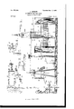
- Figure 1 is a side elevation of a railway gate and signal constructed in accordance with this invention, parts heing broken away to show the operating mech anism more clearly.
- Fig. 2 is a vertical sectional view of the central gate-tower.
- Fig. 3 is a similar View of one of the end gatetowers.
- Fig. 4 is a detail sectional view on line 4 at of Fig. 1.
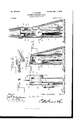
- Fig. 5 is a detail perspective view illustrating the construction of the arched connecting-piece of the signal-operat ing mechanism.
- Fig. 6 is a detail perspective View of the train device.
- Figs. 7 and 8 are detail perspective views of parts of the same.
- the towers 2 and 3 which may be constructed in any suitable manner, are provided with registering vertically-arranged guide-openings 4E and 5, and the gate is held in its open position by weights 6 and 7, mounted, respectively, in the towers 2 and 3 and connected to cables 8 and 9 or other suitable flexible connections, which pass over guide-gulleys 10 and 11.
- the front ends of the ropes or cables are attached to the top of the gate at the center and ends thereof, and the gate carries'a depressible track-bar 12, offset from the gate and the towers and connected with the former by arms or bracket-bars 13, which have angularly-bent terminals suitably secured to the track-bar 12 and the top of the gate.
- the depressible track-bar 12 which is adapted to be operated by a wheel 14 of a train device or tappet, is rigid with the gate and is pivoted at its ends to inclined sections 15, an ranged to receive the wheel 14 and guide the same to the bar 12.
- the end sections 15 of the depressible track-bar are located at both ends of the bar 12 and are pivoted at their outer terminals to supporting-bars 16, which are angularly bent near their upper ends and which are pivotally mounted in an opening 17 of a suitable block or piece 18, mounted on two of the cross-ties of the track.
- the supporting-bars 16 oscillate with the downward and upward movement of the depressible track-bars, the swinging movement of the supports 16 being limited by the end walls of the openings 17.
- Each oscillating supporting-bar 16 preferably carries a shield 0 19, constructed of sheet metal or other suit able material and adapted to extend over the opening to shed water and protect the device.
- the train device which operates the gate and which is designed to be mounted on the 5 cars of a train, comprises a bracket 20, the roller or wheel 14., which is journaled thereon, and means for detachably mounting the bracket on a car.
- the bracket 20 is provided at its top with a spindle 21 to receive the roller 10o or wheel 14, and it is composed of a lower shank and an upper L-shaped portion which oifsets the spindle from the plane of the shank.
- the upper end of the bracket is provided at opposite sides with grooves 22, arranged at a slightinclination and adapted to enable the bracket to be interlocked with a bifurcated bar or arm 22, the upper edges of the bifurcated portion of the bar or arm 22 being arranged at an inclination to correspond with the position of the grooves.
- the bar or arm 22 is designed to be secured to the top of a box-car, and the lower portion or shank of the bracket is detachably secured to the side of the car by a locking-bar 23, hinged at one end by means of a staple 24 or othersuitable device and provided between its ends with a recess 25, which engages a corresponding recess 26 of the shank of the bracket.
- the free end of the bar 23 is slotted and is.held against the car by a pin or other suitable fastening device which is adapted to engage an eye or staple 27, projecting through the slot of the locking-bar and designed to be mounted on the car.
- the train device of one car holds the gate depressed until the train device of the next car engages the same, the bar 12 being designed to be of greater length than a car.
- the device which is carried by the train is adapted also for operating a signal for warning persons of the approach of a train, and this signal preferably consists of a bell 29, mounted on the central tower and adapted to be struck by a bell-hammer 30 of a shaft 31, V which carries an arm 32, adapted to limit the rocking movement of the shaft.
- the shaft 31 carries a grooved pulley 33, to which are.
- bell-wires 34 attached to the pul ley at the top and bottom thereof and extend ing from the bell-ringing mechanism in op-' posite directions, so that the alarm may be sounded by a train approaching the crossing in either direction.
- the wires which are connected with the bell-ringing mechanism may be of any desired length, so that the warning of an approaching train may be given when the train is any desired distance from the crossing, and the said wires are supported at points between their ends by pulleys 35, mounted on uprights 36 and arranged in suitable housings 37, con-' structed of sheet metal or other material.
- each Wire is connected with an upwardly-extending arm 38 of a shaft 39, mounted on a tower or supporting-frame 40 and provided at one end with a weighted arm 41 and at its other end with an arm 42.
- - arm 42 which is arranged substantially horimounted on the shaft 39, being slotted at one end and provided with a series of notches 45, adapted to be engaged by a pin 46, which passes through the shaft and secures the arm 41 to the same.
- the outer end of the arm 41 is weighted, and it is adapted to return the mechanism to its normal position after it has been operated.
- the tower or supporting-frame 40 which may be constructed in any suitable manner, is provided with a horizontal bar 48, which extends laterally from it to provide a stop for the weighted arm or lever 41.
- the lower end of the link-bar is provided with a pivot 49, and the upper end of the link-bar is bifurcated to receive the arm 42, which is adj ustably mounted on the shaft by means of apin and a series of notches 51,Which are adapted to receive the pin or othersuitable fastening device employed for holding the arm 42 on the shaft 39.
- the depressible operating-bar 44 is normally arranged at an inclination,as illustrated in Fig. 1 of the accompanying drawings, and its outer end is supported by an arched connecting-piece 52, which is secured to a bar 53 and which extends outward therefrom.
- the bar 53 has its outer portion recessed, as
- the post or support 55 is provided at its top with a shield 56, adapted to shed water and protect the device.
- the invention has the following advan-' tages:
- the automatic railway-gate which is positive and reliable in operation, is normally maintained in an open position, and it is closed by a train passing a crossing. The gate remains closed until all the cars of a train have passed, and it is then automatically opened.
- the train device is also adapted to operate a signal for warning persons of the approach of a train, and the signal-operating mechanism may be located any desired distance from the crossing, so that ample warning will be given of an approaching train.
- the pivoted end sections arranged at an inclination, and the pivotally-mounted bars supporting the end sections, substantially as described.
- a depressible track-bar rigidly connected with the gate and adapted to be operated by apassing train for lowering the. gate, the inclined end sections, the blocks or supports provided with openings, and the oscillating supporting-bars pivotedin the openings of the blocks or supports and connected to theend sections and provided with shields, substantially as described.
- a bracket having a shank and provided with an L-shaped upper portion having grooves
- a spindle extending from the bracket
- a roller or wheel mounted on the spindle
- a bifurcated arm or bar designed to be located at the top of a car and interlocked with the grooves of the bracket
- the hinged locking-bar interlocked with the shank of the bracket, substantially as described.
Landscapes
- Engineering & Computer Science (AREA)
- Mining & Mineral Resources (AREA)
- Life Sciences & Earth Sciences (AREA)
- General Life Sciences & Earth Sciences (AREA)
- Geochemistry & Mineralogy (AREA)
- Geology (AREA)
- Train Traffic Observation, Control, And Security (AREA)
Description
Patented Mar. 7, I899.
J. JACKSON.
AUTOMATIC RAILWAY GATE.
(Applicatimi filed m 23, 1898.]
2 Sheets8heet I.
' (No Model.)
Wih esszs v c we Noam: mass :0, PNoro-umo wnsmuo'ron. n
Patented Mar. 7, I899. J. JACKSON...
AUTOMATIC RAILWAY GATE.
(Application filed my 23, 1898) 2 sheets sheet 2.
(No Model.)
an \n div @A He rnc ys Wih asszs THE "cams PETERS co.. wo'roLm-ua. WASHINGTON, 11cv NlTED STATES PATENT OFFICE.
JOHN JACKSON, OF GLENDON, NORTH CAROLINA, ASSIGNOR OF ONE-HALF TO W. K. JACKSON, OF OARTHAGE, NORTH CAROLINA.
AUTOMATIC RAILWAY-GATE.
SPECIFICATION forming part of Letters Patent No. 620,656, dated March 7, 1899.
Application filed May 23, 1898.
To all whom it may concern:
Be it known that I, JOHN J AOKSON, a citizen of the United States, residing at Glendon, in the county of Moore and State of North Carolina, have invented a new and useful Automatic Railway-Gate, of which the following is a specification.
The invention relates to improvements in automatic railway-gates.
The object of the present invention is to improve the construction of automatic railway-gates and to provide a simple and comparatively inexpensive one, which will be closed by the trains passing by it and which will be opened automatically after a train has passed.
A further object of the invention is to enable the device carried by a train for operating the gate to operate also an alarm for warning persons of the approach of a train.
The invention consists in the construction and novel combination and arrangement of parts, as hereinafter fully described, illustrated in the accompanying drawings, and pointed out in the claims hereto appended.
In the drawings, Figure 1 is a side elevation of a railway gate and signal constructed in accordance with this invention, parts heing broken away to show the operating mech anism more clearly. Fig. 2 is a vertical sectional view of the central gate-tower. Fig. 3 is a similar View of one of the end gatetowers. Fig. 4 is a detail sectional view on line 4 at of Fig. 1. Fig. 5 is a detail perspective view illustrating the construction of the arched connecting-piece of the signal-operat ing mechanism. Fig. 6 is a detail perspective View of the train device. Figs. 7 and 8 are detail perspective views of parts of the same.
Like numerals of reference designate corresponding parts in all the figures of the drawings.
1 designates a vertically-movable railwaygate guided in suitable openings or ways of a central tower 2 and end towers 3 and designed to be arranged at the side of a railroad-track, as illustrated in the accompanying drawings, and normally held elevated to 50 afford a passage-Way between the towers and Serial No. 681,485. on model.)
adapted to be lowered by a train. The towers 2 and 3, which may be constructed in any suitable manner, are provided with registering vertically-arranged guide-openings 4E and 5, and the gate is held in its open position by weights 6 and 7, mounted, respectively, in the towers 2 and 3 and connected to cables 8 and 9 or other suitable flexible connections, which pass over guide-gulleys 10 and 11. The guide-pulleys 10 and 11, which are provided at their peripheries with grooves, are journaled in the towers 2 and 3 and may be constructed in any suitable manner.
The front ends of the ropes or cables are attached to the top of the gate at the center and ends thereof, and the gate carries'a depressible track-bar 12, offset from the gate and the towers and connected with the former by arms or bracket-bars 13, which have angularly-bent terminals suitably secured to the track-bar 12 and the top of the gate. The depressible track-bar 12, which is adapted to be operated by a wheel 14 of a train device or tappet, is rigid with the gate and is pivoted at its ends to inclined sections 15, an ranged to receive the wheel 14 and guide the same to the bar 12. The end sections 15 of the depressible track-bar are located at both ends of the bar 12 and are pivoted at their outer terminals to supporting-bars 16, which are angularly bent near their upper ends and which are pivotally mounted in an opening 17 of a suitable block or piece 18, mounted on two of the cross-ties of the track. The supporting-bars 16 oscillate with the downward and upward movement of the depressible track-bars, the swinging movement of the supports 16 being limited by the end walls of the openings 17. Each oscillating supporting-bar 16 preferably carries a shield 0 19, constructed of sheet metal or other suit able material and adapted to extend over the opening to shed water and protect the device.
The train device, which operates the gate and which is designed to be mounted on the 5 cars of a train, comprises a bracket 20, the roller or wheel 14., which is journaled thereon, and means for detachably mounting the bracket on a car. The bracket 20 is provided at its top with a spindle 21 to receive the roller 10o or wheel 14, and it is composed of a lower shank and an upper L-shaped portion which oifsets the spindle from the plane of the shank. The upper end of the bracket is provided at opposite sides with grooves 22, arranged at a slightinclination and adapted to enable the bracket to be interlocked with a bifurcated bar or arm 22, the upper edges of the bifurcated portion of the bar or arm 22 being arranged at an inclination to correspond with the position of the grooves. The bar or arm 22 is designed to be secured to the top of a box-car, and the lower portion or shank of the bracket is detachably secured to the side of the car by a locking-bar 23, hinged at one end by means of a staple 24 or othersuitable device and provided between its ends with a recess 25, which engages a corresponding recess 26 of the shank of the bracket. The free end of the bar 23 is slotted and is.held against the car by a pin or other suitable fastening device which is adapted to engage an eye or staple 27, projecting through the slot of the locking-bar and designed to be mounted on the car. The train device of one car holds the gate depressed until the train device of the next car engages the same, the bar 12 being designed to be of greater length than a car.
The device which is carried by the train is adapted also for operating a signal for warning persons of the approach of a train, and this signal preferably consists of a bell 29, mounted on the central tower and adapted to be struck by a bell-hammer 30 of a shaft 31, V which carries an arm 32, adapted to limit the rocking movement of the shaft. The shaft 31 carries a grooved pulley 33, to which are.
connected bell-wires 34, attached to the pul ley at the top and bottom thereof and extend ing from the bell-ringing mechanism in op-' posite directions, so that the alarm may be sounded by a train approaching the crossing in either direction.
The wires which are connected with the bell-ringing mechanism may be of any desired length, so that the warning of an approaching train may be given when the train is any desired distance from the crossing, and the said wires are supported at points between their ends by pulleys 35, mounted on uprights 36 and arranged in suitable housings 37, con-' structed of sheet metal or other material.
The outer end of each Wire is connected with an upwardly-extending arm 38 of a shaft 39, mounted on a tower or supporting-frame 40 and provided at one end with a weighted arm 41 and at its other end with an arm 42. The
- arm 42, which is arranged substantially horimounted on the shaft 39, being slotted at one end and provided with a series of notches 45, adapted to be engaged by a pin 46, which passes through the shaft and secures the arm 41 to the same. The outer end of the arm 41 is weighted, and it is adapted to return the mechanism to its normal position after it has been operated.
The tower or supporting-frame 40, which may be constructed in any suitable manner, is provided with a horizontal bar 48, which extends laterally from it to provide a stop for the weighted arm or lever 41. The lower end of the link-bar is provided with a pivot 49, and the upper end of the link-bar is bifurcated to receive the arm 42, which is adj ustably mounted on the shaft by means of apin and a series of notches 51,Which are adapted to receive the pin or othersuitable fastening device employed for holding the arm 42 on the shaft 39.
The depressible operating-bar 44 is normally arranged at an inclination,as illustrated in Fig. 1 of the accompanying drawings, and its outer end is supported by an arched connecting-piece 52, which is secured to a bar 53 and which extends outward therefrom.
The bar 53 has its outer portion recessed, as
shown, and it is mounted in a vertical opening or recess 54 of a post 55, whereby the bar 53 is adapted to reciprocate longitudinally and move vertically to conform to the movements of the operating-bar 44. The post or support 55 is provided at its top with a shield 56, adapted to shed water and protect the device.
When the bar 44 is depressed,the upwardlyextending arm 38 swings outward, carrying with it the bell-wire and causing the bell-ham: mer to strike the bell, and as the various cars pass by the bar 44 their devices will ring the bell, so that a succession of signals will be sounded as a train approaches the crossing. When the cars have passed the crossing, the pulleys or wheels 14 pass under the inclined bar 44 without ringing the bell, the arched connecting-piece 52 offsetting the outer end of the bar 44 from the bar 53 and permitting the roller or wheel 14 to pass under the device without injuring the same. The connection of the bar 53 with the post 55 permits the bar 53 to move upward when the roller or wheel passes under the bar 44.
The invention has the following advan-' tages: The automatic railway-gate, which is positive and reliable in operation, is normally maintained in an open position, and it is closed by a train passing a crossing. The gate remains closed until all the cars of a train have passed, and it is then automatically opened. The train device is also adapted to operate a signal for warning persons of the approach of a train, and the signal-operating mechanism may be located any desired distance from the crossing, so that ample warning will be given of an approaching train.
Changes in the form, proportion, and minor details of construction may be resorted to without departing from the spirit or sacrificing any of the advantages of this invention.
ed to be operated by a passing train, the pivoted end sections arranged at an inclination, and the pivotally-mounted bars supporting the end sections, substantially as described.
2. In a device of the class described, the combination of a vertically-movable gate, means for holding the gate normally elevated,
a depressible track-bar rigidly connected with the gate and adapted to be operated by apassing train for lowering the. gate, the inclined end sections, the blocks or supports provided with openings, and the oscillating supporting-bars pivotedin the openings of the blocks or supports and connected to theend sections and provided with shields, substantially as described.
3. In a device of the class described, the combination of the towers provided with vertical openings forming ways, a vertically-movable gate guided in the openings of the towers, arms extending outward from the gate, a depressible bar mounted on the arms and adapted to be operated by a passing train, pulleys mounted in the towers, and flexible connections arranged on the pulleys, provided with weights and attached to the gate, substantially as described.
4. In a device of the class described, the combination of abracket having a spindle, a roller or wheel mounted thereon, a supporting arm or bar designed to be secured to the top of a car and detachably interlocked with the upper portion of the bracket, and ahinged locking-bar engaging the lower portion of the bracket, substantially as described.
5. In a device of the class described, the combination of a bracket having a shank and provided with an L-shaped upper portion having grooves, a spindle extending from the bracket, a roller or wheel mounted on the spindle, a bifurcated arm or bar designed to be located at the top of a car and interlocked with the grooves of the bracket, and the hinged locking-bar interlocked with the shank of the bracket, substantially as described.
In testimony that I claim the foregoing as my own I have hereto affixed my signature in the presence of two witnesses.
JOHN JACKSON.
W'itnesses:
J. W. MoGAsKILL, CHAS. P. CO E.
Publications (1)
| Publication Number | Publication Date |
|---|---|
| US620656A true US620656A (en) | 1899-03-07 |
Family
ID=2689265
Family Applications (1)
| Application Number | Title | Priority Date | Filing Date |
|---|---|---|---|
| US620656D Expired - Lifetime US620656A (en) | Automatic railway-gate |
Country Status (1)
| Country | Link |
|---|---|
| US (1) | US620656A (en) |
-
0
- US US620656D patent/US620656A/en not_active Expired - Lifetime
Similar Documents
| Publication | Publication Date | Title |
|---|---|---|
| US620656A (en) | Automatic railway-gate | |
| US739681A (en) | Railway-signal. | |
| US496960A (en) | Gate for railroad-crossings | |
| US556211A (en) | Railway-gate | |
| US750264A (en) | Warning-signal for railroad-crossings | |
| US489365A (en) | Railroad-crossing gate and signal | |
| US662918A (en) | Automatic signal for railway-crossings. | |
| US978921A (en) | Crossing-signal. | |
| US340390A (en) | Railroad alarm-signal | |
| US793301A (en) | Railway-train signal. | |
| US269394A (en) | Railroad-signal | |
| US351336A (en) | Signal-alarm and safety-gate for railway-crossings | |
| US797210A (en) | Automatic railway-gate. | |
| US318015A (en) | Signaling apparatus | |
| US363808A (en) | Eailwat gate | |
| US147846A (en) | Improvement in railroad-signals | |
| US580105A (en) | Field | |
| US427395A (en) | Automatic gate for railway-crossings | |
| US543414A (en) | Automatic railway-gate | |
| US1458885A (en) | Crossing signal for railroads | |
| US600932A (en) | Railroad-gate | |
| US166024A (en) | Improvement in railroad-signals | |
| US243892A (en) | Railroad signal and gate | |
| US345412A (en) | Automatic railway-signal | |
| US335243A (en) | Railway-signal |