BACKGROUND OF THE INVENTION
The present invention relates to valves, and, more particularly, to an improved valve system that permits relatively easy assembly, disassembly and reassembly of the valve.
A variety of valve designs and configurations are available for use for material handling requirements, particularly for industrial applications. Numerous design criteria and operational parameters are required for the valves in such industrial applications.
Such industrial disc valves can be used for food, pharmaceutical, nuclear or toxic chemical applications. As such, the valve must be compatible with a wide variety of materials, some of which may be sticky, gummy, abrasive, granular, pelletized, and/or possess other troublesome characteristics. Handling of such materials through the valve over time typically results in fouling, jamming, leakage or other problems, which in turn results in poor valve performance. Importantly, the valve must be reliable to provide smooth and efficient operation without damage to the material flowing there through when in an open or partially opened configuration.
One type of valve currently available for industrial use is referred to as a disc valve in which a movable valve member, typically in the shape of a disc, is pivotally mounted within the bore or opening in a valve body. In a fully closed configuration, the disc is in sealing contact with a peripheral portion of the bore formed in the valve body to prevent the flow of material through the valve, and in a partial or fully open configuration, the valve disc is pivoted to permit the partial or full flow of material through the valve. An actuator, which may be pneumatic, manual or otherwise, is coupled to the shaft on which the disc valve member pivots for opening and closing of the valve.
Due to the nature of many of the materials being handled by industrial disc valves, such as sticky, gummy, abrasive or similarly characterized materials, periodic cleaning of the valve is required. Such periodic maintenance generally requires removal, disassembly, and cleaning of the valve, and any other sanitization. Optimally, the downtime of the system in which the valve is utilized should be minimized to avoid an excessive and detrimental economic impact to the industrial or other production cycle and maintenance manpower costs.
In many instances, industrial disc valves utilized in food, pharmaceutical, nuclear or toxic chemical environments are operated in highly restrictive, clean room, limited access or other specialized environments. As such, operators that service such systems must wear protective clothing, uniforms, gloves, goggles and other equipment to avoid contamination of the processed materials and/or potential injury and harm to themselves. Such protective clothing, particularly gloves, render it very difficult and cumbersome to easily, efficiently and quickly assemble and disassemble industrial equipment such as a disc valve. Moreover, the improved operational performance and efficiency of the disc valve is the purpose for the maintenance in many instances in the first place, and must not be compromised upon reassembly of the components. For example, accurate positioning of the components of the disc valve relative to one another, and associated clearances or tolerances must be maintained, for optimal operation as previously described. Under such conditions, the precise reassembly of known disc valves after cleaning is difficult, as the accurate and precise manipulation of the needed tools and valve components is required.
Therefore, there is a need for an improved disc valve for industrial applications which can be easily and conveniently disassembled and reassembled, preferably without the use of hand tools even by an operator wearing protective clothing and gloves while still maintaining exacting operational parameters of the valve after that disassembly and reassembly.
SUMMARY OF THE INVENTION
These and other objectives of the invention have been attained by an improved valve assembly which is capable of being entirely disassembled and reassembled manually without the benefit of tools or other potentially cumbersome and difficult to manipulate instruments. Moreover, upon reassembly of the disc valve of this invention, the disc valve member is automatically centered relative to a bore in the valve body, thereby providing proper clearance and tolerance for reliable and consistent operation of the valve upon reinstallation into the material handling system.
In a presently preferred embodiment, the valve assembly according to this invention includes a valve member in the form of a dome-shaped disc having a pair of projecting valve arms. The disc is housed within the bore of a valve body, and is mounted for pivotal movement therein on a pair of respective shafts coupled to the valve arms. The shafts are seated within holes in the valve body for rotational movement, and one of the shafts is coupled to an actuator for selective rotation of the shafts and, thereby, pivotal movement of the disc within the valve body to and between closed and opened positions.
Each shaft preferably includes a spline portion located adjacent to an annular recess on the shaft. A shoulder or detent borders the annular recess. Each valve arm includes a spline hole to receive therein the spline portion of one of the shafts for releasably coupling the valve arms to the respective shafts and, thereby, transmitting the rotation of the shaft to pivot the disc within the valve body. Importantly, the shoulder or detent adjacent to the annular recess on each of the shafts engages or abuts against the valve arm for accurately and precisely positioning the disc relative to the valve body and bore. As such, upon reassembly of the valve the disc is automatically and accurately positioned relative to the valve body without adjustment or calibration by the user.
Each shaft is preferably secured to the valve body by a shaft retainer plate. The shaft retainer plate is secured to the valve body by a plurality of bolts and thumb screws for easy manual installation and removal of the shaft retainer plates without the benefit of hand tools.
Another important feature of the present invention in a preferred embodiment is the ease and expertise with which each of the components of the valve assembly can be securely assembled together. A valve seat is releasably coupled to the valve body in sealing engagement with the disc valve in a closed position to thereby effectively and reliably prevent the flow of material through the valve. The valve seat is sandwiched between a portion of the valve body and a seat retaining ring. The seat retaining ring and valve seat are securely clamped to the valve body during assembly and reassembly by a clamp ring which includes a pair of semicircular members pivotally coupled together. When the clamp ring is installed onto the valve body and seat retaining ring, it surrounds a perimeter of the seat retaining ring and a portion of the valve body, thereby clamping the two members together with the valve seat there between. The clamp includes a manually operable latch for easy and convenient manipulation and operation during disassembly and reassembly of the valve. The clamping force produced by the clamp of this invention is at least as good as prior designs while offering significantly easier operation and use.
Accordingly, the present invention, including the valve assembly itself and the method of assembly, disassembly and use of the valve assemblies, solves the above-described disadvantages of known prior art disc valves by providing a sturdy, reliable and effective disc valve for industrial applications which can be easily and quickly assembled and disassembled, even by a user wearing a protective suit and gloves, in a timely and efficient manner. Moreover, the required clearances or tolerances of the disc valve member within the valve body are accurately and automatically achieved upon reassembly to provide for effective closure and precise opening of the valve as required during operation.
BRIEF DESCRIPTION OF THE DRAWINGS
The objectives and features of the invention will become more readily apparent from the following detailed description taken in conjunction with the accompanying drawings in which:
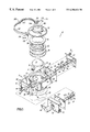
FIG. 1 is an exploded perspective view of the components of a presently preferred embodiment of a valve assembly according to this invention;
FIG. 2 is a cross-sectional side elevational view of an assembled valve of the valve components shown in FIG. 1;
FIG. 3 is a cross-sectional view taken along line 3—3 of FIG. 2 showing the interaction of a spline portion of one of the shafts of the valve assembly with an arm connected to the disc valve member;
FIG. 4 is a schematic representation of a locking pin engaged with a drive shaft according to the invention;
FIG. 5 is a schematic representation of the valve assembly in a partially open configuration; and
FIG. 6 is a view similar to FIG. 5 with the valve assembly in a fully open configuration.
DETAILED DESCRIPTION OF THE INVENTION
A presently preferred embodiment of the valve assembly according to this invention is shown in FIG. 1. The valve assembly 10 includes a valve member 12 in the shape of a dome-shaped valve disc having a pair of valve arms 14 depending downwardly therefrom. The valve member 12 preferably may be 316 stainless steel, and is pivotally mounted within a through bore 16 in a valve body 18 which also preferably may be 316 stainless steel. The valve body 18 includes upper and lower flanges 20, 22 formed at the upper and lower ends, respectively, of a cylindrical portion 24 of the valve body 18. The lower flange 22 which may be configured for ANSI or other industry convention compatibility for mating with upstream components 21 and downstream components 23. The upper flange is preferably configured as described below. An annular channel 26 is formed between the upper flange 20 and a lip 28 projecting inwardly toward the valve bore 16. The lip 28 includes a lower beveled or tapered surface which is contoured to conform with the dome-shaped valve disc 12 to allow for the movement to and between closed and open positions of the valve disc 12. The closed position of the valve assembly 10 is shown in FIG. 2 and partially and fully open positions of the valve assembly 10 are shown in FIGS. 5 and 6, respectively.
The valve body 18 also includes a peripheral frame 30 including oppositely spaced mounting plates 32 (which preferably may be of 316 stainless steel) which are welded or otherwise attached to the corresponding opposite ends of a pair of bowed valve body plates 34 (which also preferably may be of 316 stainless steel). The central regions of the valve body plates 34 are welded or otherwise attached to the exterior of the side wall 36 of the valve body's cylindrical portion 24 between the upper and lower flanges 20, 22. A number, preferably four, of threaded bolts 38 project through each mounting plate 32 as shown in FIG. 1, and are welded or otherwise secured thereto.
Diametrically opposed collars 40 are mounted on a transverse axis A of the valve assembly 10 to the side wall 36 of the cylindrical portion 24 of the valve body 18. Each collar 40 surrounds an aperture 42 through which one of two shafts 44 (each preferably may be 316 stainless steel) is inserted. Each shaft 44 projects through one of the collars 40 and a tubular bushing 46, with a circular disc-shaped flange 48 projecting from one end thereof, surrounds the shaft 44. The tubular portion of the bushing 46 is inserted within the aperture 42 of the collar 40. The bushing 46 preferably may be glass-filled Teflon, or alternatively brass, stainless steel or another appropriate material. When assembled, as shown in FIG. 2, the disc-shaped flange 48 of the bushing 46 is sandwiched between the outer edge of the collar 40 and an annular shaft retaining brace 50 fixed to the shaft 44.
Each shaft 44 also preferably may include one or a pair of spaced annular groves 52 into which are seated one or a pair of O-rings 54, which preferably may be made of Viton. When the shaft 44 is inserted through the respective bushing 46 seated in the collar 40, the O-rings 54 provide a vacuum or partial vacuum sealing engagement with the bushing 46 so as to permit vacuum or similar operation of the valve assembly 10. A spline portion 56 is formed at a terminal or distal end of each shaft 44, and is received in a mating spline hole 57 in the associated valve arm 14. An annular recess 58 is formed in each shaft 44 adjacent to the spline portion 56. The annular recess 58 is bordered by a shoulder or detent 60 at the opposite end of the annular recess 58 from the spline portion 56.
One of the shafts 44 of the valve assembly 10 in the presently preferred embodiment is a drive shaft 44 a that is coupled to an actuator 62 which may be in the form of a handle as shown in FIG. 1, or any other appropriate actuator such as a pneumatic or otherwise driven device appropriate for the particular process system or application requirements. A proximal end of the drive shaft 44 a is coupled to the actuator 62 through an appropriately configured opening 64 in a shaft retaining plate 66 and an opening 68 in a generally C-shaped actuator bracket 70 (which preferably may be 304 stainless steel). The bracket 70 and shaft retaining plate 66 are manually and releasably mounted to the mounting plate 32 of the valve body 18 by thumb screws, wing nuts or other manually operable fasteners 72 (preferably may be 18-8 stainless steel) threadably mounted onto the threaded shaft of the bolts 38 projecting from the mounting plate 32. The opposite shaft 44 is aligned with the drive shaft 44 a on the transverse axis A, and constitutes an idler shaft 44 b which is likewise secured to the valve assembly 10 by a shaft retaining plate 66, thumb screws, wing nuts or other appropriate manually operable fasteners 72 on the threaded portions of the bolts 38 projecting from the associated mounting plate 32. The shaft retaining brace 50 on each of the shafts 44 abuts against the associated shaft retaining plate 66 when installed on the mounting plate 32 to thereby accurately position the shaft 44 along the transverse axis A when the valve 10 is assembled.
It should be readily appreciated that rotational movement of the handle or other appropriate actuator 62 transmitted through the drive shaft 44 a coupled to the valve disc member 12 via the spline portion 56 and spline hole 57, and similarly the idler shaft 44 b, pivotally moves the valve disc member 12 within the bore 16 to and between open and closed positions.
As shown particularly in FIGS. 1 and 4, a preferably spring biased safety locking pin 76 is preferably inserted through a hole 78 in one of the valve body plates 34 which is aligned with a hole or multiple circumferentially spaced holes 80 in the drive shaft 44 a to thereby prevent rotation of the shaft 44 a and pivotal movement of the valve disc 12 when the locking pin 76 is inserted. Advantageously, insertion of the locking pin 76 will fix the location of the valve disc 12 within the bore 16 in a closed, open or partially open configuration as required depending upon the position of the hole 80 in the shaft 44 a. The valve disc 12 is typically relatively heavy and could potentially cause injury to a human finger or the like in its path, so the locking pin 76 is helpful as a safety precaution to prevent potential injury to an operator during servicing, disassembly or re-assembly of the valve 10.
An annular valve seat 82, preferably made of glass-filled Teflon, is seated within the channel 26 of the valve body 18. The valve seat 82 includes a raised sill 84 surrounding the inner portion thereof. A tapered or beveled edge 86 adjacent to the lower surface of the valve seat 82, and surrounding the inner circumference thereof, is pressed into sealing engagement with the dome surface of the valve disc 12 when the valve disc 12 is in a closed or partially closed configuration. A seat retaining ring 88 (which preferably may be 316 stainless steel) in one presently preferred embodiment includes a base 90 and a central circular opening 92 defined by an upwardly extending generally L-shaped annular flange 94 welded or otherwise secured to the inner circumference of the opening 92 in the base 90. The outer dimensions of the base 90 are the same as those of the outer periphery of the upper flange 20 of the cylindrical portion 24 of the valve body 18. A downwardly projecting annular extension 96 is formed on the bottom surface of the base 90 of the seat retaining ring 88. The extension 96 is sized and configured to seat within the channel 26 formed in the cylindrical portion 24 of the valve body 18 in relation to the generally planar upper portion of the valve seat 82, as shown in FIG. 2.
A number of shims 98 (which preferably may be of virgin Teflon), three of which are shown in FIG. 1, are provided with the valve assembly 10 according to the presently preferred embodiment of this invention. The shims 98 are selectively positioned above and/or below the valve seat 82 to accurately position the valve seat 82 into sealing engagement with the valve disc 12 in order to provide an effective and positive seal there between depending on the specific geometry, tolerances, and clearances which may result from operational wear or manufacturing practices. The shims 98 will raise or lower the valve seat 82 relative to the valve disc 12 as appropriate for the desired clearances, tolerances or other relationships.
Advantageously, the seat retaining ring 88, valve seat 82 and associated shims 98 are easily, quickly and securely clamped to the valve body 18 during assembly and reassembly, and are easily removed therefrom during disassembly of the valve 10, as allowed for by a clamp 100 in the form of a clamp ring having two semicircular members 102 pivotally coupled together at adjacent ends thereof. Each semicircular clamp member 102 has a generally C-shaped cross-sectional configuration so that when the clamp ring 100 is positioned around the perimeter of the seat retaining ring 88 and the outer circumference of the upper flange 20 of the valve body 18 with the valve seat 82 and shims 98 there between, the perimeter edge of the seat retaining ring 88 and of the upper flange 20 are captured within the clamp ring 100. The distal ends of each member 102 of the clamp ring 100 include a bifurcated stem 104 which cooperate together to form a latch 106 for releasably securing the clamp ring 100 onto the valve body 18 and seat retaining ring 88. The bifurcated stem 104 a of one of the clamp ring members 102 includes a seat or a recess 108 to receive therein the cooperating portion of the latch 106 on the other bifurcated stem 104 b. The cooperating portion of the latch 106 includes a threaded rod 110 pivotally coupled between the bifurcated arms of the stem 104 b with a manually operable lug 112 threadably mounted on the rod 110.
As such, with the clamp ring members 102 pivoted toward each other around the perimeter of the seat retaining ring 88 and the upper flange 20 of the valve body 18, the threaded rod 110 of the latch 106 is pivoted toward and between the arms of the bifurcated stem 104 a on the opposite clamp member 102. The lug 112 is rotated in a first direction to close the latch 106 and securely tighten the clamp 100, and in a second opposite direction to loosen the clamp 100 for removal and disassembly of the valve. Therefore, access to the valve disc 12, valve seat 82, seat retaining ring 88, and subsequent disassembly of the valve 10 can be easily accomplished manually without hand tools by an operator even when wearing a protective suit and/or gloves.
Referring specifically to FIGS. 2 and 3, during assembly of the valve 10, the spline portions 56 of each shaft 44 are inserted through the associated collar 40 in the valve body 18 with the bushing 46 seated therein until they project into the bore 16 of the valve body 18. The spline portions 56 are received within the spline openings 57 in the respective valve arms 14 of the valve disc 12 which has been appropriately pre-positioned in the valve body 18. The position of the valve disc 12 is automatically centered relative to the longitudinal axis B of the valve assembly 10 once the spline portions 56 of each of the shafts 44 are inserted into the respective valve arms 14 because the shoulder detent 60 bordering the annular recess 58 on each shaft 44 contacts, engages or otherwise abuts against the confronting surface of the respective valve arm 14 as specifically shown in FIGS. 2 and 3. The protruding elements or keys 56 a of the spline portion 56 of each shaft 44 contact the confronting surface of the valve arm 14, thereby limiting the lateral movement of the valve disc 12 along the transverse axis A. As such, the valve member or valve disc 12 is accurately centered and positioned for sealing engagement when in a closed or partially closed configuration with respect to the valve seat 82. The position of the shafts 44 within the collars 40 and relative to the valve body 18 is accurately maintained with the respective shaft retaining plates 66 contacting the outer surface of the associated shaft retaining brace 50, as shown particularly in FIG. 2. Therefore, lateral movement of the shafts 44 and the valve disc 12 is limited, and the valve disc 12 is accurately and reliably positioned in the valve body 18 when the valve 10 is assembled without further adjustment, modification or attention by the user.
From the above disclosure of the general principles of the present invention, and the preceding detailed description of at least one preferred embodiment, those skilled in the art will readily comprehend the various modifications to which this invention is susceptible. Therefore, I desire to be limited only by the scope of the following claims and equivalents thereof.