US6205675B1 - Dehydration machine - Google Patents
Dehydration machine Download PDFInfo
- Publication number
- US6205675B1 US6205675B1 US09/472,827 US47282799A US6205675B1 US 6205675 B1 US6205675 B1 US 6205675B1 US 47282799 A US47282799 A US 47282799A US 6205675 B1 US6205675 B1 US 6205675B1
- Authority
- US
- United States
- Prior art keywords
- drums
- stuff
- tank
- mesh
- drum
- Prior art date
- Legal status (The legal status is an assumption and is not a legal conclusion. Google has not performed a legal analysis and makes no representation as to the accuracy of the status listed.)
- Expired - Fee Related
Links
- 230000018044 dehydration Effects 0.000 title claims abstract description 20
- 238000006297 dehydration reaction Methods 0.000 title claims abstract description 20
- 239000002184 metal Substances 0.000 claims abstract description 21
- XLYOFNOQVPJJNP-UHFFFAOYSA-N water Substances O XLYOFNOQVPJJNP-UHFFFAOYSA-N 0.000 claims abstract description 13
- 230000002411 adverse Effects 0.000 claims abstract description 3
- 230000003247 decreasing effect Effects 0.000 claims description 3
- 239000002761 deinking Substances 0.000 description 6
- 238000000034 method Methods 0.000 description 6
- 230000008569 process Effects 0.000 description 5
- 239000000835 fiber Substances 0.000 description 4
- 239000007788 liquid Substances 0.000 description 3
- 238000003825 pressing Methods 0.000 description 2
- 238000007789 sealing Methods 0.000 description 2
- 229910001111 Fine metal Inorganic materials 0.000 description 1
- 230000006835 compression Effects 0.000 description 1
- 238000007906 compression Methods 0.000 description 1
- 230000000694 effects Effects 0.000 description 1
- 238000001914 filtration Methods 0.000 description 1
- 238000009434 installation Methods 0.000 description 1
- 238000012423 maintenance Methods 0.000 description 1
- 230000004048 modification Effects 0.000 description 1
- 238000012986 modification Methods 0.000 description 1
- 239000002994 raw material Substances 0.000 description 1
- 238000004064 recycling Methods 0.000 description 1
- 230000004044 response Effects 0.000 description 1
- 238000006467 substitution reaction Methods 0.000 description 1
- 239000008400 supply water Substances 0.000 description 1
- 239000002699 waste material Substances 0.000 description 1
Images

Classifications
-
- D—TEXTILES; PAPER
- D21—PAPER-MAKING; PRODUCTION OF CELLULOSE
- D21F—PAPER-MAKING MACHINES; METHODS OF PRODUCING PAPER THEREON
- D21F1/00—Wet end of machines for making continuous webs of paper
- D21F1/66—Pulp catching, de-watering, or recovering; Re-use of pulp-water
- D21F1/74—Pulp catching, de-watering, or recovering; Re-use of pulp-water using cylinders
-
- B—PERFORMING OPERATIONS; TRANSPORTING
- B01—PHYSICAL OR CHEMICAL PROCESSES OR APPARATUS IN GENERAL
- B01D—SEPARATION
- B01D33/00—Filters with filtering elements which move during the filtering operation
- B01D33/06—Filters with filtering elements which move during the filtering operation with rotary cylindrical filtering surfaces, e.g. hollow drums
- B01D33/073—Filters with filtering elements which move during the filtering operation with rotary cylindrical filtering surfaces, e.g. hollow drums arranged for inward flow filtration
-
- B—PERFORMING OPERATIONS; TRANSPORTING
- B01—PHYSICAL OR CHEMICAL PROCESSES OR APPARATUS IN GENERAL
- B01D—SEPARATION
- B01D33/00—Filters with filtering elements which move during the filtering operation
- B01D33/35—Filters with filtering elements which move during the filtering operation with multiple filtering elements characterised by their mutual disposition
- B01D33/37—Filters with filtering elements which move during the filtering operation with multiple filtering elements characterised by their mutual disposition in parallel connection
-
- B—PERFORMING OPERATIONS; TRANSPORTING
- B01—PHYSICAL OR CHEMICAL PROCESSES OR APPARATUS IN GENERAL
- B01D—SEPARATION
- B01D33/00—Filters with filtering elements which move during the filtering operation
- B01D33/44—Regenerating the filter material in the filter
- B01D33/46—Regenerating the filter material in the filter by scrapers, brushes nozzles or the like acting on the cake-side of the filtering element
- B01D33/466—Regenerating the filter material in the filter by scrapers, brushes nozzles or the like acting on the cake-side of the filtering element scrapers
-
- B—PERFORMING OPERATIONS; TRANSPORTING
- B01—PHYSICAL OR CHEMICAL PROCESSES OR APPARATUS IN GENERAL
- B01D—SEPARATION
- B01D33/00—Filters with filtering elements which move during the filtering operation
- B01D33/58—Handling the filter cake in the filter for purposes other than for regenerating the filter cake remaining on the filtering element
- B01D33/60—Handling the filter cake in the filter for purposes other than for regenerating the filter cake remaining on the filtering element for washing
-
- B—PERFORMING OPERATIONS; TRANSPORTING
- B01—PHYSICAL OR CHEMICAL PROCESSES OR APPARATUS IN GENERAL
- B01D—SEPARATION
- B01D33/00—Filters with filtering elements which move during the filtering operation
- B01D33/58—Handling the filter cake in the filter for purposes other than for regenerating the filter cake remaining on the filtering element
- B01D33/62—Handling the filter cake in the filter for purposes other than for regenerating the filter cake remaining on the filtering element for drying
- B01D33/64—Handling the filter cake in the filter for purposes other than for regenerating the filter cake remaining on the filtering element for drying by compression
- B01D33/646—Handling the filter cake in the filter for purposes other than for regenerating the filter cake remaining on the filtering element for drying by compression by pressure rollers
-
- B—PERFORMING OPERATIONS; TRANSPORTING
- B01—PHYSICAL OR CHEMICAL PROCESSES OR APPARATUS IN GENERAL
- B01D—SEPARATION
- B01D33/00—Filters with filtering elements which move during the filtering operation
- B01D33/80—Accessories
- B01D33/802—Device for changing the inclination of the filtering element
-
- B—PERFORMING OPERATIONS; TRANSPORTING
- B01—PHYSICAL OR CHEMICAL PROCESSES OR APPARATUS IN GENERAL
- B01D—SEPARATION
- B01D33/00—Filters with filtering elements which move during the filtering operation
- B01D33/80—Accessories
- B01D33/804—Accessories integrally combined with devices for controlling the filtration
-
- D—TEXTILES; PAPER
- D21—PAPER-MAKING; PRODUCTION OF CELLULOSE
- D21C—PRODUCTION OF CELLULOSE BY REMOVING NON-CELLULOSE SUBSTANCES FROM CELLULOSE-CONTAINING MATERIALS; REGENERATION OF PULPING LIQUORS; APPARATUS THEREFOR
- D21C9/00—After-treatment of cellulose pulp, e.g. of wood pulp, or cotton linters ; Treatment of dilute or dewatered pulp or process improvement taking place after obtaining the raw cellulosic material and not provided for elsewhere
- D21C9/18—De-watering; Elimination of cooking or pulp-treating liquors from the pulp
Definitions
- This invention relates to a dehydration machine for dehydrating stuff such as used papers or virgin pulps.
- An example of such machine is provided with a screw in a drum.
- the machine was designed to separate used paper into fibers and liquid by simply rotating, using the screws, used papers with liquid in the drum.
- this machine it was inevitable that a large amount of fibers flows out of the drum.
- the present inventors discover that it is effective to dehydrate used papers prior to the deinking process to enhance the deinking efficiency in the process. Based on the discover, the present inventors have accomplished the present invention.
- the object of the present invention is to provide a dehydration machine which can effectively dehydrate stuff such as used papers or virgin pulps.
- the mesh member provided on one of the drums is a metal fine mesh
- the mesh member provided on the other of the drums is a metal course mesh
- the mesh member may include an inner metal mesh and an outer metal mesh, wherein the inner metal mesh is twice coarser than the outer metal mesh.
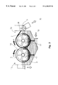
- FIG. 1 is an explanatory view showing an embodiment of a dehydration machine according to the present invention.
- FIG. 2 is a cross sectional view showing main elements of the dehydration machine according to the present invention.
- FIG. 1 is a side view of the whole structure of the concentration and dehydration machine according to the present invention.
- FIG. 2 is a vertical cross sectional view showing the essential part of the machine.
- the machine includes a main body base 1 .
- a stuff tank 2 comprised of a right half tank and a left half tank connected by a flexible sealing member 12 .
- the right half tank and the left half tank are supported by a first bracket 4 and a second bracket 6 , respectively.
- the first bracket 4 supports a right-hand rotatable dehydration drum 3 (hereinafter referred to as “immovable drum”)
- the second bracket 6 supports a left-hand rotatable dehydration drum 5 (hereinafter referred to as “inclinable drum”).
- the right side bottom portion of the second bracket 6 is rotatably connected to a fixing bracket 7 so as to be inclined about a fulcrum 8 .
- the immovable drum 3 is allowed only to rotate about its axis.
- the inclinable drum 5 is allowed not only to rotate but also to be slightly inclined together with the second bracket 6 about the fulcrum 8 .
- An air spring 9 is provided so as to support the left side bottom portion of the second bracket 6 .
- a securing piece 11 is provided at the left side bottom portion of the second bracket 6 so as to be engaged with a pressure limit stopper 10 attached to a third bracket 20 equipped at a left end of the main body base 1 .
- a stuff inlet 13 is equipped at the lower portion of the stuff tank (raw material tank) 2 .
- a conveyor 14 and a stuff outlet 15 are equipped.
- a stuff overflow mouth 16 is equipped. The stuff overflowed from the stuff overflow mouth 16 is returned to a stuff tank (not shown).
- the left half tank 2 is repeatedly inclined with respect to the right half tank via the flexible sealing member 12 by increasing and reducing the pressure of the air spring 9 between a condition shown in a dotted line and a condition shown in a solid line shown in FIG. 1 . Therefore, the compression degree of the stuff can be changed in accordance with the slightly increased or decreased area of the tangent portion (i.e., contact portion) of the immovable drum 3 and the inclinable drum 5 .
- the pressure limit stopper 10 is equipped so as to regulate the pressure caused between the immovable drum 3 and the inclinable drum 5 , the pressure to be applied to the stuff can be adjusted. Furthermore, the deformation of these drums 3 and 5 can be prevented.
- the stuff is introduced into the stuff tank 2 through the stuff inlet 13 equipped at the lower portion of the stuff tank 2 in which two cylindrical drums each made of a punched metal and having a water passage are provided.
- An outer surface of a circumferential wall of the immovable drum 3 is covered with a mesh member including an outer fine metal mesh (e.g. a 25-mesh net) and an inner mesh twice coarser than the outer mesh.
- an outer surface of a circumferential wall of the inclinable drum 5 is covered with a mesh member including an outer coarse metal mesh (e.g. a 16-mesh net) and an inner metal mesh twice coarser than the outer metal mesh.
- a mesh member including an outer coarse metal mesh (e.g. a 16-mesh net) and an inner metal mesh twice coarser than the outer metal mesh.
- the water level of the stuff raises gradually. As shown in FIG. 2, the water flows into these drums 3 and 5 through the metal meshes and the apertures of the punched metal, and then flows out of these drums 3 and 5 through the water outlets 17 .
- the fibers of the stuff are compressed at the tangent portion (i.e., the contact portion) of the immovable drum 3 and the inclinable drum 5 to be dehydrated.
- the water contained in the stuff flows into the drums 3 and 5 , and then flows out of the drums 3 and 5 through the water outlets 17 . This wasted water is filtered to be purified by passing the outer and inner meshes and the punched metal, which results in recyclable water.
- the dehydration drums by rotating the two dehydration drums with metal meshes that are different in mesh size, a natural filtration and dehydration are performed. It is also possible to instantly and effectively dehydrate the stuff between the two dehydration drums by applying pressure therebetween using the air spring 9 . Furthermore, the dehydrated paper fibers are attached in a sheet-like manner to a circumference of one of the two dehydration drums having a finer mesh, and stripped down by a scraper 18 when rotated by about 120 degree, then delivered by the conveyer 14 to perform the next process (i.e., deinking process).
- the immovable drum 3 and the inclinable drum 5 rotate in the direction of arrows A and B shown in FIG. 2, respectively.
- showers 19 are also provided so as to supply water when required.
- the motor (not shown) may be small in size and power. However, the rotational speed of the motor may be adjusted at a wide range.
- the machine according to the present invention can also be used for dehydrating virgin pulps or the like.
- the machine can dehydrate the stuff effectively before introducing the stuff into a deinking device, which enhances the deinking efficiency in the deinking device.
- the stuff introduced at a concentration of 3 to 5% at the inlet side can be concentrated and dehydrated effectively to a concentration of 15 to 30% at the outlet side.
- the processing efficiency can be unified by applying pressure by the air cushion regardless of the fluctuates of the concentration of the stuff at the inlet side.
- An installation space can be compact, and the maintenance can be performed easily.
Abstract
A dehydration machine includes a stuff tank, a stuff inlet provided at a lower portion of the stuff tank, a stuff outlet provided at an upper portion of the stuff tank, and a pair of drums each having a circumferential wall with a plurality of water passage apertures, the pair of drums being juxtaposed in the stuff tank. The pair of drums rotate adversely about its respective axis so as to introduce stuffs in the stuff tank therebetween from a lower side thereof. One of the drum is rotatable in an immovable manner, and the other of the drums is rotatable in an inclinable manner while being urged toward the one of the drums by an air spring. Each of the drums is provided with a metal net on an outer surface of the circumferential wall.
Description
1. Field of the Invention
This invention relates to a dehydration machine for dehydrating stuff such as used papers or virgin pulps.
2. Description of Related Art
Recycling of used papers has been demanded in the paper making industry for a long time in view of the need to better protect the natural environment. In this connection, various kinds of used paper processing machines have been developed in response to an increased demand of used papers.
An example of such machine is provided with a screw in a drum. The machine was designed to separate used paper into fibers and liquid by simply rotating, using the screws, used papers with liquid in the drum. However, in this machine, it was inevitable that a large amount of fibers flows out of the drum. Furthermore, it is not feasible to recycle the waste liquid that flows out of the drum because ink or the like is mixed therein.
The present inventors discover that it is effective to dehydrate used papers prior to the deinking process to enhance the deinking efficiency in the process. Based on the discover, the present inventors have accomplished the present invention.
The object of the present invention is to provide a dehydration machine which can effectively dehydrate stuff such as used papers or virgin pulps.
According to the present invention, a dehydration machine includes a stuff tank, a stuff inlet provided at a lower portion of the stuff tank, a stuff outlet provided at an upper portion of the stuff tank, and a pair of drums each having a circumferential wall with a plurality of water passage apertures, wherein the pair of drums is juxtaposed in the stuff tank. The pair of drums rotate adversely about its respective axis so as to introduce stuffs in the stuff tank therebetween from a lower side thereof. One of the drum is rotatable in an immovable manner, and the other of the drums is rotatable in an inclinable manner while being urged toward the one of the drums by an air spring. Each of the drums is provided with a mesh member on an outer surface of the circumferential wall.
It is also preferable that the mesh member provided on one of the drums (i.e., the immovable drum) is a metal fine mesh, and the mesh member provided on the other of the drums (i.e., the inclinable drum) is a metal course mesh.
The mesh member may include an inner metal mesh and an outer metal mesh, wherein the inner metal mesh is twice coarser than the outer metal mesh.
Other objects and advantages of the present invention will become apparent from the detailed description of the preferred embodiments with reference to the attached drawings, wherein:
FIG. 1 is an explanatory view showing an embodiment of a dehydration machine according to the present invention; and
FIG. 2 is a cross sectional view showing main elements of the dehydration machine according to the present invention.
Now referring to the drawings, an embodiment of the present invention is described.
FIG. 1 is a side view of the whole structure of the concentration and dehydration machine according to the present invention. FIG. 2 is a vertical cross sectional view showing the essential part of the machine.
Firstly, the concentration and dehydration machine as a whole will be explained. The machine includes a main body base 1. Provided on the main body base 1 is a stuff tank 2 comprised of a right half tank and a left half tank connected by a flexible sealing member 12. The right half tank and the left half tank are supported by a first bracket 4 and a second bracket 6, respectively. The first bracket 4 supports a right-hand rotatable dehydration drum 3 (hereinafter referred to as “immovable drum”), and the second bracket 6 supports a left-hand rotatable dehydration drum 5 (hereinafter referred to as “inclinable drum”). The right side bottom portion of the second bracket 6 is rotatably connected to a fixing bracket 7 so as to be inclined about a fulcrum 8.
The immovable drum 3 is allowed only to rotate about its axis. On the other hand, the inclinable drum 5 is allowed not only to rotate but also to be slightly inclined together with the second bracket 6 about the fulcrum 8. An air spring 9 is provided so as to support the left side bottom portion of the second bracket 6. In order to regulate the limit of pressure applied to the second bracket 6 by the air spring 9, a securing piece 11 is provided at the left side bottom portion of the second bracket 6 so as to be engaged with a pressure limit stopper 10 attached to a third bracket 20 equipped at a left end of the main body base 1.
A stuff inlet 13 is equipped at the lower portion of the stuff tank (raw material tank) 2. At an upper side of the immovable drum 3, a conveyor 14 and a stuff outlet 15 are equipped. At the upper side of the inclinable drum 5, a stuff overflow mouth 16 is equipped. The stuff overflowed from the stuff overflow mouth 16 is returned to a stuff tank (not shown).
The left half tank 2 is repeatedly inclined with respect to the right half tank via the flexible sealing member 12 by increasing and reducing the pressure of the air spring 9 between a condition shown in a dotted line and a condition shown in a solid line shown in FIG. 1. Therefore, the compression degree of the stuff can be changed in accordance with the slightly increased or decreased area of the tangent portion (i.e., contact portion) of the immovable drum 3 and the inclinable drum 5.
Since the pressure limit stopper 10 is equipped so as to regulate the pressure caused between the immovable drum 3 and the inclinable drum 5, the pressure to be applied to the stuff can be adjusted. Furthermore, the deformation of these drums 3 and 5 can be prevented.
Next, referring to FIG. 2, the structure of the machine and the operation thereof will be explained.
The stuff is introduced into the stuff tank 2 through the stuff inlet 13 equipped at the lower portion of the stuff tank 2 in which two cylindrical drums each made of a punched metal and having a water passage are provided. An outer surface of a circumferential wall of the immovable drum 3 is covered with a mesh member including an outer fine metal mesh (e.g. a 25-mesh net) and an inner mesh twice coarser than the outer mesh.
On the other hand, an outer surface of a circumferential wall of the inclinable drum 5 is covered with a mesh member including an outer coarse metal mesh (e.g. a 16-mesh net) and an inner metal mesh twice coarser than the outer metal mesh. These two drums 3 and 5 are juxtaposed with a slight space therebetween as shown in FIGS. 1 and 2. The immovable drum 3 is allowed only to rotate by a motor and a decelerator (not shown). In contrast, the inclinable drum 5 is allowed to be inclined by increasing or decreasing the pressure of the air spring 9 while being rotated by the motor (not shown) and the decelerator (not shown).
When the stuff is introduced into the tank 2 through the stuff inlet 13, the water level of the stuff raises gradually. As shown in FIG. 2, the water flows into these drums 3 and 5 through the metal meshes and the apertures of the punched metal, and then flows out of these drums 3 and 5 through the water outlets 17. On the other hand, the fibers of the stuff are compressed at the tangent portion (i.e., the contact portion) of the immovable drum 3 and the inclinable drum 5 to be dehydrated. The water contained in the stuff flows into the drums 3 and 5, and then flows out of the drums 3 and 5 through the water outlets 17. This wasted water is filtered to be purified by passing the outer and inner meshes and the punched metal, which results in recyclable water.
With the structure described above, by rotating the two dehydration drums with metal meshes that are different in mesh size, a natural filtration and dehydration are performed. It is also possible to instantly and effectively dehydrate the stuff between the two dehydration drums by applying pressure therebetween using the air spring 9. Furthermore, the dehydrated paper fibers are attached in a sheet-like manner to a circumference of one of the two dehydration drums having a finer mesh, and stripped down by a scraper 18 when rotated by about 120 degree, then delivered by the conveyer 14 to perform the next process (i.e., deinking process). The immovable drum 3 and the inclinable drum 5 rotate in the direction of arrows A and B shown in FIG. 2, respectively. Showers 19 are also provided so as to supply water when required. The motor (not shown) may be small in size and power. However, the rotational speed of the motor may be adjusted at a wide range.
Although the aforementioned embodiment is directed to the machine for dehydrating used papers, the machine according to the present invention can also be used for dehydrating virgin pulps or the like.
The machine can dehydrate the stuff effectively before introducing the stuff into a deinking device, which enhances the deinking efficiency in the deinking device.
The following effects can be obtained as a result of the structure described above.
(1) When this dehydration machine is used, the stuff introduced at a concentration of 3 to 5% at the inlet side can be concentrated and dehydrated effectively to a concentration of 15 to 30% at the outlet side.
(2) As a natural vacuum method is adopted, the power cost can be minimized.
(3) As a high concentration process can be performed instantly, the stuff flow can be simplified.
(4) As a concentration of wasted water is extremely low, yield rate can be improved and the wasted water can be purified so as to be recycled.
(5) The processing efficiency can be unified by applying pressure by the air cushion regardless of the fluctuates of the concentration of the stuff at the inlet side.
(6) An installation space can be compact, and the maintenance can be performed easily.
(7) The machine functions well even if a smaller motor with smaller horse power is used.
The present invention claims priority based on Japanese Patent is Application No. H10-372299 filed on Dec. 28, 1998, the content of which is incorporated hereinto by reference in its entirety.
The terms and descriptions in this specification are used only for explanatory purposes and the present invention is not limited to these, but many modifications and substitutions may be made without departing from the spirit of the scope of the present invention which is defined by the appended claims.
Claims (4)
1. A dehydration machine, comprising:
a stuff tank;
a stuff inlet provided at a lower portion of said stuff tank;
a stuff outlet provided at an upper portion of said stuff tank; and
a pair of drums each having a circumferential wall with a plurality of water passage apertures, said pair of drums being juxtaposed in said stuff tank,
wherein said pair of drums rotate adversely about its respective axis so as to introduce stuffs in said stuff tank therebetween from a lower side thereof, one of said drum being rotatable in an immovable manner, and the other of said drums being rotatable in an inclinable manner while being urged toward said one of said drums by an air spring, and
wherein each of said drums is provided with a mesh member on an outer surface of said circumferential wall.
2. The dehydration machine according to claim 1, wherein said mesh member provided on said one of said drums is a metal fine mesh, and said mesh member provided on said the other of said drums is a metal course mesh.
3. The dehydration machine according to claim 2, wherein said mesh member includes an inner metal mesh and an outer metal mesh, said inner metal mesh being twice coarser than said outer metal mesh.
4. The dehydration machine according to claim 1, wherein said the other of said drums is repeatedly inclined with respect to said one of said drums by increasing and decreasing a pressure of said air spring.
Applications Claiming Priority (2)
| Application Number | Priority Date | Filing Date | Title |
|---|---|---|---|
| JP10-372299 | 1998-12-28 | ||
| JP37229998A JP3433905B2 (en) | 1998-12-28 | 1998-12-28 | Concentrator dehydrator |
Publications (1)
| Publication Number | Publication Date |
|---|---|
| US6205675B1 true US6205675B1 (en) | 2001-03-27 |
Family
ID=18500210
Family Applications (1)
| Application Number | Title | Priority Date | Filing Date |
|---|---|---|---|
| US09/472,827 Expired - Fee Related US6205675B1 (en) | 1998-12-28 | 1999-12-28 | Dehydration machine |
Country Status (2)
| Country | Link |
|---|---|
| US (1) | US6205675B1 (en) |
| JP (1) | JP3433905B2 (en) |
Cited By (5)
| Publication number | Priority date | Publication date | Assignee | Title |
|---|---|---|---|---|
| US20070061369A1 (en) * | 2005-09-09 | 2007-03-15 | Microsoft Corporation | User interface for creating a spreadsheet data summary table |
| US20100042913A1 (en) * | 2005-10-27 | 2010-02-18 | Microsoft Corporation | Variable formatting of cells |
| US20100251090A1 (en) * | 2006-02-27 | 2010-09-30 | Microsoft Corporation | Dynamic Thresholds for Conditional Formats |
| US9223772B2 (en) | 2005-09-09 | 2015-12-29 | Microsoft Technology Licensing, Llc | Filtering user interface for a data summary table |
| US20220355225A1 (en) * | 2021-05-10 | 2022-11-10 | Lyco Manufacturing Inc. | Externally Fed Screen for Filtration |
Families Citing this family (1)
| Publication number | Priority date | Publication date | Assignee | Title |
|---|---|---|---|---|
| JP7208618B2 (en) * | 2018-12-28 | 2023-01-19 | 株式会社大善 | Concentrated dehydrator |
Citations (7)
| Publication number | Priority date | Publication date | Assignee | Title |
|---|---|---|---|---|
| US4079524A (en) * | 1975-08-18 | 1978-03-21 | Bertin & Cie | Mechanical drying apparatus |
| US4102791A (en) * | 1975-10-08 | 1978-07-25 | Klockner-Humboldt-Deutz Aktiengesellschaft | Double drum vacuum filter |
| US4663040A (en) * | 1985-11-22 | 1987-05-05 | Elizondo H J | Rotary drum filter grid extension and method |
| US4782747A (en) * | 1986-12-11 | 1988-11-08 | Unger Daniel D | Roll press for recovering liquid from pulp |
| US5666741A (en) * | 1995-03-03 | 1997-09-16 | Voith Sulzer Papiermaschinen Gmbh | Drying section with additional press nip |
| US5669155A (en) * | 1995-10-04 | 1997-09-23 | Tubular Textile Llc | Suction drum system for processing web materials particularly knitted fabrics |
| US6004468A (en) * | 1998-07-17 | 1999-12-21 | Barbulescu; Adrian | Serial drum apparatus and method for processing wet material |
-
1998
- 1998-12-28 JP JP37229998A patent/JP3433905B2/en not_active Expired - Lifetime
-
1999
- 1999-12-28 US US09/472,827 patent/US6205675B1/en not_active Expired - Fee Related
Patent Citations (7)
| Publication number | Priority date | Publication date | Assignee | Title |
|---|---|---|---|---|
| US4079524A (en) * | 1975-08-18 | 1978-03-21 | Bertin & Cie | Mechanical drying apparatus |
| US4102791A (en) * | 1975-10-08 | 1978-07-25 | Klockner-Humboldt-Deutz Aktiengesellschaft | Double drum vacuum filter |
| US4663040A (en) * | 1985-11-22 | 1987-05-05 | Elizondo H J | Rotary drum filter grid extension and method |
| US4782747A (en) * | 1986-12-11 | 1988-11-08 | Unger Daniel D | Roll press for recovering liquid from pulp |
| US5666741A (en) * | 1995-03-03 | 1997-09-16 | Voith Sulzer Papiermaschinen Gmbh | Drying section with additional press nip |
| US5669155A (en) * | 1995-10-04 | 1997-09-23 | Tubular Textile Llc | Suction drum system for processing web materials particularly knitted fabrics |
| US6004468A (en) * | 1998-07-17 | 1999-12-21 | Barbulescu; Adrian | Serial drum apparatus and method for processing wet material |
Cited By (13)
| Publication number | Priority date | Publication date | Assignee | Title |
|---|---|---|---|---|
| US9959267B2 (en) | 2005-09-09 | 2018-05-01 | Microsoft Technology Licensing, Llc | Filtering user interface for a data summary table |
| US8601383B2 (en) | 2005-09-09 | 2013-12-03 | Microsoft Corporation | User interface for creating a spreadsheet data summary table |
| US9223772B2 (en) | 2005-09-09 | 2015-12-29 | Microsoft Technology Licensing, Llc | Filtering user interface for a data summary table |
| US9529789B2 (en) | 2005-09-09 | 2016-12-27 | Microsoft Technology Licensing, Llc | User interface for creating a spreadsheet data summary table |
| US20070061369A1 (en) * | 2005-09-09 | 2007-03-15 | Microsoft Corporation | User interface for creating a spreadsheet data summary table |
| US10579723B2 (en) | 2005-09-09 | 2020-03-03 | Microsoft Technology Licensing, Llc | User interface for creating a spreadsheet data summary table |
| US20100042913A1 (en) * | 2005-10-27 | 2010-02-18 | Microsoft Corporation | Variable formatting of cells |
| US8286072B2 (en) | 2005-10-27 | 2012-10-09 | Microsoft Corporation | Variable formatting of cells |
| US9424235B2 (en) | 2005-10-27 | 2016-08-23 | Microsoft Technology Licensing, Llc | Variable formatting of values |
| US11295058B2 (en) | 2005-10-27 | 2022-04-05 | Microsoft Technology Licensing, Llc | Variable formatting of values |
| US20100251090A1 (en) * | 2006-02-27 | 2010-09-30 | Microsoft Corporation | Dynamic Thresholds for Conditional Formats |
| US8914717B2 (en) | 2006-02-27 | 2014-12-16 | Microsoft Corporation | Dynamic thresholds for conditional formats |
| US20220355225A1 (en) * | 2021-05-10 | 2022-11-10 | Lyco Manufacturing Inc. | Externally Fed Screen for Filtration |
Also Published As
| Publication number | Publication date |
|---|---|
| JP3433905B2 (en) | 2003-08-04 |
| JP2000189726A (en) | 2000-07-11 |
Similar Documents
| Publication | Publication Date | Title |
|---|---|---|
| US4283275A (en) | Apparatus for processing waste paper | |
| US5622267A (en) | Method and pressure screen for screening fibre suspension | |
| US3833468A (en) | System for recovery of fiber from paper mill effluent, including a sieve bend screen | |
| US6205675B1 (en) | Dehydration machine | |
| TW444077B (en) | Method and apparatus for screening waste paper pulp | |
| GB1475422A (en) | Method of and apparatus for recovering paper fibres from materials containing waste paper | |
| EP0424426B1 (en) | Method and apparatus for the removal of light material from a fiber suspension | |
| US5423993A (en) | Fiber recovery system and process | |
| FI88732C (en) | Procedure and apparatus for treating backwater | |
| US20090223873A1 (en) | Screening apparatus for a contaminated fibrous suspension and its use | |
| CN1844566A (en) | Method for dissolving and purifying paper material containing impurity | |
| US7163604B2 (en) | Production of fiber suspension from waste paper | |
| EP0721526B1 (en) | Method and apparatus for dewatering of a fibre suspension | |
| ES2024904A6 (en) | A method for processing waste paper | |
| EP3260596B1 (en) | Deashing system and deashing method | |
| US3330487A (en) | Method and apparatus for loosening fibers of waste paper | |
| US20060144796A1 (en) | Process and device for aerating suspensions | |
| JPS5934834B2 (en) | Method and apparatus for recovering paper fibers from raw materials including waste paper | |
| US8444807B2 (en) | Method for preparing paper pulp from recycled paper containing contaminants | |
| US3387794A (en) | Method of the automatic processing of paper stocks | |
| EP1996763B1 (en) | Screening apparatus | |
| SU1161617A1 (en) | Fibrous suspension classifier | |
| ES8701881A1 (en) | Sorting apparatus for fibre suspensions. | |
| JP2001500572A (en) | Method of pulping and deinking | |
| Möller | European Wastepaper and Waste Paper Processing Systems |
Legal Events
| Date | Code | Title | Description |
|---|---|---|---|
| AS | Assignment |
Owner name: TAIZEN COMPANY LIMITED, JAPAN Free format text: ASSIGNMENT OF ASSIGNORS INTEREST;ASSIGNORS:IDE, TETSUO;IDE, TAKEFUMI;REEL/FRAME:010509/0719 Effective date: 19991213 |
|
| REMI | Maintenance fee reminder mailed | ||
| LAPS | Lapse for failure to pay maintenance fees | ||
| STCH | Information on status: patent discontinuation |
Free format text: PATENT EXPIRED DUE TO NONPAYMENT OF MAINTENANCE FEES UNDER 37 CFR 1.362 |
|
| FP | Lapsed due to failure to pay maintenance fee |
Effective date: 20050327 |