US6202974B1 - Portable easel with adjustable board support - Google Patents
Portable easel with adjustable board support Download PDFInfo
- Publication number
- US6202974B1 US6202974B1 US09/050,136 US5013698A US6202974B1 US 6202974 B1 US6202974 B1 US 6202974B1 US 5013698 A US5013698 A US 5013698A US 6202974 B1 US6202974 B1 US 6202974B1
- Authority
- US
- United States
- Prior art keywords
- easel
- legs
- leg
- sections
- board support
- Prior art date
- Legal status (The legal status is an assumption and is not a legal conclusion. Google has not performed a legal analysis and makes no representation as to the accuracy of the status listed.)
- Expired - Lifetime
Links
Images

Classifications
-
- A—HUMAN NECESSITIES
- A47—FURNITURE; DOMESTIC ARTICLES OR APPLIANCES; COFFEE MILLS; SPICE MILLS; SUCTION CLEANERS IN GENERAL
- A47B—TABLES; DESKS; OFFICE FURNITURE; CABINETS; DRAWERS; GENERAL DETAILS OF FURNITURE
- A47B97/00—Furniture or accessories for furniture, not provided for in other groups of this subclass
- A47B97/04—Easels or stands for blackboards or the like
- A47B97/08—Easels or stands for blackboards or the like foldable
Definitions
- This invention relates to a novel portable easel with an adjustable board support, and is more particularly concerned with such a display holding device which is easily and rapidly set up, is capable of adjustably securing a graphic display in a selected position, and which may be selectively quickly collapsed and set up again without special tools or capabilities and which may be conveniently stored and transported in minimum space.
- Conventional easels usually comprise a tripod or similar arrangement of legs comprised of telescoped tubes or foldable struts which may be extended linearly to a desired height and which have a display support platform across one or more of the tubes or struts,
- the tubes or struts are usually held in extended position by means of a thumb or set screw or screw collar or similar fastening means locking one tube or strut to the adjacent tube or strut.
- the thumb screw or screw collar is turned-and one tube is telescoped into an adjacent tube, or the struts are pivotally folded together.
- the display platform may be adjustable along the tubes or struts and conventionally secured at a desired height by conventional fastening means.
- a plurality of sets of tubes or legs are pivotally connected together at one end or the head of the easel tripod. These sets may be pivotally spread apart, with one end of each set secured to the tripod, to form legs for the easel.
- the head includes means for limiting the spread of the legs.
- Each set of tubes comprises a tripod leg, and each leg is made up of several interlocked sections, preferably telescoped together. Each telescopic section has an end of reduced diameter, and that reduced diameter end is fit interlocked into the other end of the adjacent section.
- each leg Within the tubes of each leg is a bungee cord like elastic rope, connected at one end near the tripod head to its adjacent uppermost section and at the other end near the foot of the leg on the last tubular section in the set remote from the head.
- This elastic rope is under tension, tending to pull the tubular sections together, but still allowing them to be pulled apart by hand manipulative force.
- the tubes are folded side to side, the sets are compact and the tube section are not arranged linearly and are separated from one another, forming a bundle of side to side sections.
- the elastic rope allows each section to swing free and be drawn together telescopically, with the reduced diameter end of one section being drawn home into the open end of the adjacent tube.
- a pair of novel display board holders or supports are arranged preferably one each on two of the three tripod legs.
- This support has two positions: one extended from the leg on which is mounted or a second position folded against the leg on which it is mounted. When extended, the support is locked into position on its leg, and the support is capable of holding a display spanning both like supports at a selected height. When folded, the support is not only compactly arranged and folded against the leg, but also it may be slid along the section of the leg on which it is mounted or onto an adjacent section into another selected position, to the full height of the leg, so that display boards of selected various heights may be handled.
- These locking, binding and sliding positions for the support depend upon whether nubs or projections on the support engage the leg.
- the adjacent legs sections must be of a constant diameter to permit the support to be moved upwardly or downwardly from interlocked section to the adjacent section of the leg.
- Another object of the invention is to provide a portable easel composed of interlocked telescoped tubular sections urged together by elastic means.
- Another object is to provide a portable easel composed of multiple legs and a cooperating adjustable display support, each leg having co-planar sections which may be selectively interlocking or collapsed, each section having a surface for adjustably moving the display support from section to section.
- Another object is to provide a tripod type easel having an adjustable display support, wherein an elastic cord is secured to its legs at its tripod end and at the end of the easel remote from its tripod end within multiple interlocking tubular sections normally urged into tensioned interlocking engagement but which can be separated and folded against one another when not in interlocking engagement.
- Another object is to provide a tripod type collapsible easel having an adjustable display support which is composed of folded multiple sections joined together by an elastic cord, which may be set up by manipulation of its tripod to arrange the sections in linearly interlocked extended position.
- Another object is to provide a tripod type collapsible easel having a plurality of legs each consisting of interlocked members and having a display support arranged on one or more of the interlocked members, wherein the display support may be pivotally folded away from a leg for supporting a display on the easel and pivotally folded against the leg for adjustment of the height of the display support along the leg and for transport and storage.
- Another object is to provide a display support for a tripod type collapsible easel which has nubs to selectively secure the display support in an extended position for mounting a display on the support or in a folded position when collapsing the easel or adjusting the height of the support on the easel.
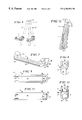
- FIG. 1 is a perspective view of the easel embodying the present invention showing the easel as it is being set up by unfolding of its sections.
- FIG. 2 is a perspective view of the set up easel embodying the present invention.
- FIG. 3 is a detailed view showing the interlocking telescopic arrangement of typical tubular leg sections of the easel and the elastic cord shown within the sections.
- FIG. 4 is a detailed perspective view showing the adjustable board support folded against a tubular leg section.
- FIG. 5 is a detailed perspective view showing the board support folded away from the tubular leg section.
- FIG. 6 is a detailed perspective view of a pair of board supports in an extended position showing the supports arranged on the easel legs, which are depicted in broken lines.
- FIG. 7 is an perspective view of the board support.
- FIG. 8 is a top plan view of the board support.
- FIG. 9 is an end view of one end the board support.
- FIG. 10 is an end view of one end of the board support remote from the end shown in FIG. 9 .
- FIG. 11 is a bottom plan view of the board support.
- FIG. 12 illustrates the novel easel in folded and bundled condition.
- the portable easel 10 with its adjustable board support 11 embodying the present invention comprises a tripod head 12 which has extending from it several legs 13 , preferably three, and a foot 14 which may be installed on each of the legs.
- Each of the legs 13 comprise multiple interlocked telescopic sections 15 .
- Each leg 13 preferably is pivotally secured to the head 12 by a rivet 16 .
- the leg 13 can pivot from a position where the legs are aligned side by side to a position where the legs are spread to the position shown in FIG. 2, limited by the wall 17 of the tripod head 12 .
- each of the other sections 15 b - 15 e has one end 21 which has a reduced diameter and shoulder stop 22 so it will telescope into the other end 18 of each respective adjoining sections 15 a - 15 d .
- the extreme or bottom end 19 of each section 15 e remote from the head 12 carries the foot 14 to complete each of the legs 13 .
- each leg 13 Arranged within each leg 13 is a elastic cord 20 , one end of which is anchored in the upper section 15 a at the head 12 and the other end of which is anchored to the lower leg section 15 e .
- This elastic cord 20 is under tension drawing the sections 15 a - 15 e telescoped nested together, but the tension is limited so that by hand manipulation, the sections 15 a - 15 e may be disengaged, as shown in FIGS. 1 and 3, and folded so that the sections 15 may be arranged in a side by side position in the manner shown in FIG. 1 and fully bundled as shown in FIG. 12 .
- the collapsed easel When folded so that the sections 15 are side by side, the collapsed easel is compact and may be easily placed into a brief case for storage and transport. To erect the easel 10 , it is necessary only to hold the tripod head 12 and shake the sections 15 , in the manner shown in FIG. 1, where they are telescopically drawn together as extended legs 13 and these legs are pivoted outwardly on the head 12 into the position shown in FIG. 2 .
- a board support 11 is preferably mounted on two of the three legs 13 .
- Each board support 11 has two positions, one where it is folded against the leg 13 on which it is mounted, as shown in FIG. 4, and one where it is folded away from the leg as shown in FIGS. 2 and 5.
- the support 11 When folded against its leg 13 , the support 11 may be moved upwardly or downwardly along all of the sections 15 a - 15 e of the leg 13 on which it is mounted in the direction of the arrow in FIG. 4, the sections being of the same constant diameter and smooth and unencumbered when nested telescoped together, as described.
- the support 11 is bound in place and will not move, except under substantial pressure, so that it can support a display mounted on it, and the display may be leaned against the leg 13 on which the support is mounted.
- the support When in folded position as shown in FIG. 4, the support will not inhibit folding of the sections side by side into a compact assembly for storage and transport as previously described.
- This support 11 comprises a channel-like structure as shown in FIGS. 6-11, which preferably may be molded from thermoplastic material.
- This channel-like structure has a bottom wall 30 and spaced apart upstanding walls 31 sized substantially configured to the leg sections 15 .
- At one end of the support 11 there are a pair of spaced apart upstanding ears 32 , each having a trailing wall 33 intended to prevent a display from slipping off of the support when extended as shown in FIG. 6 .
- These ears 32 are flexible and together with the cut-outs 34 in the bottom wall 30 adjacent each of the ears as well as inwardly extending nubs 35 on each ear permits each ear to spread slightly and to snap-engage the leg 13 when the support is folded against the leg.
- the end of the support remote from the ears 32 has a base 36 extending upwardly and angularly disposed from the channel bottom wall 30 and an aperture 37 sized to loosely fit over the leg sections 15 .
- base 36 extending into this aperture 37 are two sets of projections, an upper pair 39 and a lower pair 40 .
- the lower rear wall 38 of the base 36 is cut out to permit folding of the support 11 upwardly against its leg 13 .
- These projections 39 and 40 each snap-engage the leg 13 when the support 1 I 1 is folded fully down to maintain the support in display holding position.
- the upper wall 38 and lower wall 42 of the base aperture secure the support 11 in rigid position to hold a display. While a preferred embodiment of the invention has been disclosed, many modifications and changes in the structure may be made without departing from the spirit or scope of the invention. Accordingly, it is not desired that the invention should be limited to the exact construction disclosed.
Abstract
Description
Claims (17)
Priority Applications (1)
| Application Number | Priority Date | Filing Date | Title |
|---|---|---|---|
| US09/050,136 US6202974B1 (en) | 1998-03-30 | 1998-03-30 | Portable easel with adjustable board support |
Applications Claiming Priority (1)
| Application Number | Priority Date | Filing Date | Title |
|---|---|---|---|
| US09/050,136 US6202974B1 (en) | 1998-03-30 | 1998-03-30 | Portable easel with adjustable board support |
Publications (1)
| Publication Number | Publication Date |
|---|---|
| US6202974B1 true US6202974B1 (en) | 2001-03-20 |
Family
ID=21963556
Family Applications (1)
| Application Number | Title | Priority Date | Filing Date |
|---|---|---|---|
| US09/050,136 Expired - Lifetime US6202974B1 (en) | 1998-03-30 | 1998-03-30 | Portable easel with adjustable board support |
Country Status (1)
| Country | Link |
|---|---|
| US (1) | US6202974B1 (en) |
Cited By (18)
| Publication number | Priority date | Publication date | Assignee | Title |
|---|---|---|---|---|
| US6601805B1 (en) | 2001-09-18 | 2003-08-05 | Martin Universal Design | Collapsible art easel |
| US20030201376A1 (en) * | 2002-04-29 | 2003-10-30 | Colin Knight | Devices and method for hanging a display board |
| US6719259B2 (en) * | 2001-12-28 | 2004-04-13 | Jason Huang | Adjustable board support for easel |
| US20060060747A1 (en) * | 2004-09-17 | 2006-03-23 | Haur Luen Enterprise Co., Ltd. | Portable easel |
| US20060185496A1 (en) * | 2004-12-30 | 2006-08-24 | Roland Meinl Musikinstrumente Gmbh & Co. Kg | Conga stand |
| US20060192071A1 (en) * | 2005-02-28 | 2006-08-31 | Choi Hyoung K | Angle adjustable easel |
| US20070090265A1 (en) * | 2005-09-20 | 2007-04-26 | Carl Fasano | Easel |
| US20070164173A1 (en) * | 2006-01-18 | 2007-07-19 | Wei-Chiang Li | Collapsible garbage bag supporter |
| US7374144B1 (en) | 2006-08-23 | 2008-05-20 | Wonderling James B | Folding portable easel |
| US20080116347A1 (en) * | 2006-11-22 | 2008-05-22 | Michael John Stengel | Collapsible easel |
| US20100051777A1 (en) * | 2008-09-02 | 2010-03-04 | Office Images, Inc. | Collapsible Top Hanger Easel |
| US20120018597A1 (en) * | 2009-09-04 | 2012-01-26 | Tamrac, Inc. | Tripod to support photographic equipment with tripod legs that quickly convert from a folded condition to an assembled condition |
| US20130193284A1 (en) * | 2010-04-18 | 2013-08-01 | Christian Hamm-Dubischar | Stand structure |
| US9390640B1 (en) * | 2013-05-10 | 2016-07-12 | Allen Coleman | Decorative flag display assembly |
| US10679595B2 (en) * | 2016-10-28 | 2020-06-09 | Sheldon LAVINEWAY | Apparatus for supporting musical instruments |
| CN113524951A (en) * | 2020-04-15 | 2021-10-22 | 安徽恒泰工程咨询有限公司 | Portable drawing board for engineering design |
| US20220228702A1 (en) * | 2020-06-10 | 2022-07-21 | Shenzhen Intelliark Technology Co., Ltd | Telescopic bendable support structure, camera support device, fan and lamp |
| US20220299158A1 (en) * | 2021-03-18 | 2022-09-22 | Emmanuel Linteau | Compact Tripod as Temporary Marker |
Citations (10)
| Publication number | Priority date | Publication date | Assignee | Title |
|---|---|---|---|---|
| US260068A (en) * | 1882-06-27 | van kirk | ||
| US2744712A (en) * | 1953-12-08 | 1956-05-08 | Franz D Brandt | Easel |
| US2973933A (en) * | 1959-04-10 | 1961-03-07 | Arlington Aluminum Co | Foldable tripod easel |
| US3886700A (en) * | 1973-08-27 | 1975-06-03 | William M Lambert | Collapsible structural member |
| US4017049A (en) * | 1972-05-22 | 1977-04-12 | Q-Panel Company | Easel |
| US4171116A (en) * | 1977-03-03 | 1979-10-16 | Beckley-Cardy Company | Adjustable and collapsible easel |
| US4320832A (en) * | 1979-08-06 | 1982-03-23 | Richard Edstrom | Clip for holding safety razor |
| US4326687A (en) * | 1980-07-30 | 1982-04-27 | James David Mfg. Corp. | Plural leg stand |
| US4712756A (en) * | 1986-04-23 | 1987-12-15 | Photoflex Products | Shock corded tripod stand |
| US5125613A (en) * | 1991-09-23 | 1992-06-30 | Q-Panel Corporation | Easel |
-
1998
- 1998-03-30 US US09/050,136 patent/US6202974B1/en not_active Expired - Lifetime
Patent Citations (10)
| Publication number | Priority date | Publication date | Assignee | Title |
|---|---|---|---|---|
| US260068A (en) * | 1882-06-27 | van kirk | ||
| US2744712A (en) * | 1953-12-08 | 1956-05-08 | Franz D Brandt | Easel |
| US2973933A (en) * | 1959-04-10 | 1961-03-07 | Arlington Aluminum Co | Foldable tripod easel |
| US4017049A (en) * | 1972-05-22 | 1977-04-12 | Q-Panel Company | Easel |
| US3886700A (en) * | 1973-08-27 | 1975-06-03 | William M Lambert | Collapsible structural member |
| US4171116A (en) * | 1977-03-03 | 1979-10-16 | Beckley-Cardy Company | Adjustable and collapsible easel |
| US4320832A (en) * | 1979-08-06 | 1982-03-23 | Richard Edstrom | Clip for holding safety razor |
| US4326687A (en) * | 1980-07-30 | 1982-04-27 | James David Mfg. Corp. | Plural leg stand |
| US4712756A (en) * | 1986-04-23 | 1987-12-15 | Photoflex Products | Shock corded tripod stand |
| US5125613A (en) * | 1991-09-23 | 1992-06-30 | Q-Panel Corporation | Easel |
Cited By (23)
| Publication number | Priority date | Publication date | Assignee | Title |
|---|---|---|---|---|
| US6601805B1 (en) | 2001-09-18 | 2003-08-05 | Martin Universal Design | Collapsible art easel |
| US6719259B2 (en) * | 2001-12-28 | 2004-04-13 | Jason Huang | Adjustable board support for easel |
| US20030201376A1 (en) * | 2002-04-29 | 2003-10-30 | Colin Knight | Devices and method for hanging a display board |
| US7147196B2 (en) | 2002-04-29 | 2006-12-12 | General Binding Corporation | Devices and method for hanging a display board |
| US20060060747A1 (en) * | 2004-09-17 | 2006-03-23 | Haur Luen Enterprise Co., Ltd. | Portable easel |
| US20060185496A1 (en) * | 2004-12-30 | 2006-08-24 | Roland Meinl Musikinstrumente Gmbh & Co. Kg | Conga stand |
| US20060192071A1 (en) * | 2005-02-28 | 2006-08-31 | Choi Hyoung K | Angle adjustable easel |
| US20070090265A1 (en) * | 2005-09-20 | 2007-04-26 | Carl Fasano | Easel |
| US20070164173A1 (en) * | 2006-01-18 | 2007-07-19 | Wei-Chiang Li | Collapsible garbage bag supporter |
| US7374144B1 (en) | 2006-08-23 | 2008-05-20 | Wonderling James B | Folding portable easel |
| US20080116347A1 (en) * | 2006-11-22 | 2008-05-22 | Michael John Stengel | Collapsible easel |
| US7823857B2 (en) * | 2006-11-22 | 2010-11-02 | Swank Audio Visuals Llc | Collapsible easel |
| US20100051777A1 (en) * | 2008-09-02 | 2010-03-04 | Office Images, Inc. | Collapsible Top Hanger Easel |
| US20120018597A1 (en) * | 2009-09-04 | 2012-01-26 | Tamrac, Inc. | Tripod to support photographic equipment with tripod legs that quickly convert from a folded condition to an assembled condition |
| US9228695B2 (en) * | 2009-09-04 | 2016-01-05 | Guragear, Llc | Tripod to support photographic equipment with tripod legs that quickly convert from a folded condition to an assembled condition |
| US20130193284A1 (en) * | 2010-04-18 | 2013-08-01 | Christian Hamm-Dubischar | Stand structure |
| US9151437B2 (en) * | 2010-04-18 | 2015-10-06 | Alfred-Wegener-Institut Helmholtz-Zentrum Fuer Polar-Und Meeresforschung | Stand structure |
| US9390640B1 (en) * | 2013-05-10 | 2016-07-12 | Allen Coleman | Decorative flag display assembly |
| US10679595B2 (en) * | 2016-10-28 | 2020-06-09 | Sheldon LAVINEWAY | Apparatus for supporting musical instruments |
| CN113524951A (en) * | 2020-04-15 | 2021-10-22 | 安徽恒泰工程咨询有限公司 | Portable drawing board for engineering design |
| US20220228702A1 (en) * | 2020-06-10 | 2022-07-21 | Shenzhen Intelliark Technology Co., Ltd | Telescopic bendable support structure, camera support device, fan and lamp |
| US11746950B2 (en) * | 2020-06-10 | 2023-09-05 | Shenzhen Intelliark Technology Co., Ltd | Telescopic pivotable support structure, camera support device, fan and lamp |
| US20220299158A1 (en) * | 2021-03-18 | 2022-09-22 | Emmanuel Linteau | Compact Tripod as Temporary Marker |
Similar Documents
| Publication | Publication Date | Title |
|---|---|---|
| US6202974B1 (en) | Portable easel with adjustable board support | |
| US6662815B2 (en) | Canopy support frame for a sunshade | |
| US6634304B2 (en) | Collapsible table | |
| US4609174A (en) | Foldable easel | |
| US6354316B1 (en) | Skeleton for umbrella tent | |
| US4111217A (en) | Arctic tent pole | |
| US7395561B2 (en) | Support device | |
| US6732663B2 (en) | Foldable table | |
| US5421549A (en) | Support stand for optical equipment | |
| US7636194B2 (en) | Portable screen assembly | |
| US8806676B2 (en) | Portable hammock and hammock frame | |
| US20060192071A1 (en) | Angle adjustable easel | |
| US9295866B2 (en) | Portable ballet bar exercise device | |
| US9228695B2 (en) | Tripod to support photographic equipment with tripod legs that quickly convert from a folded condition to an assembled condition | |
| JP3560367B2 (en) | Portable rack | |
| US20070075209A1 (en) | Easel with support structure | |
| US20220170287A1 (en) | Telescopic tent pole | |
| US6682042B2 (en) | Collapsible music stand | |
| US20020104557A1 (en) | Adjusting sleeve assembly for a sunshade with a tiltable canopy | |
| US4046348A (en) | Adjustable height stool | |
| US4813644A (en) | Telescoping music stand | |
| US20050189719A1 (en) | Collapsible frame assembly for supporting netting | |
| US7849848B2 (en) | Erectable and stowable decorative firebowl and stand assembly | |
| JP3207461U (en) | Tripod with connecting member | |
| US7431257B1 (en) | Foldable painting stand |
Legal Events
| Date | Code | Title | Description |
|---|---|---|---|
| AS | Assignment |
Owner name: QUARTET MANUFACTURING COMPANY, ILLINOIS Free format text: ASSIGNMENT OF ASSIGNORS INTEREST;ASSIGNOR:RELLINGER, MICHAEL;REEL/FRAME:009109/0138 Effective date: 19980324 |
|
| AS | Assignment |
Owner name: HARRIS TRUST AND SAVINGS BANK, AS AGENT, ILLINOIS Free format text: SECURITY AGREEMENT;ASSIGNORS:GENERAL BINDING CORPORATION;VELOBIND, INC.;REEL/FRAME:010360/0404 Effective date: 19991112 |
|
| STCF | Information on status: patent grant |
Free format text: PATENTED CASE |
|
| AS | Assignment |
Owner name: HARRIS TRUST AND SAVINGS BANK, AS AGENT, ILLINOIS Free format text: COLLATERAL AGREEMENT;ASSIGNOR:GENERAL BINDING CORPORATION;REEL/FRAME:012483/0216 Effective date: 20020111 |
|
| AS | Assignment |
Owner name: HARRIS TRUST AND SAVINGS BANK, AS AGENT, ILLINOIS Free format text: COLLATERAL AGREEMENT;ASSIGNOR:VELOBIND, INCORPORATED;REEL/FRAME:013305/0409 Effective date: 20020111 |
|
| REMI | Maintenance fee reminder mailed | ||
| FPAY | Fee payment |
Year of fee payment: 4 |
|
| SULP | Surcharge for late payment | ||
| AS | Assignment |
Owner name: GENERAL BINDING CORPORATION, ILLINOIS Free format text: RELEASE AND REASSIGNMENT OF PATENTS;ASSIGNOR:HARRIS N.A., SUCCESSOR BY MERGER WITH HARRIS TRUST AND SAVINGS BANK;REEL/FRAME:016438/0050 Effective date: 20050817 |
|
| AS | Assignment |
Owner name: VELOBIND, INCORPORATED, ILLINOIS Free format text: RELEASE AND REASSIGNMENT OF PATENTS;ASSIGNOR:HARRIS N.A., SUCCESSOR BY MERGER WITH HARRIS TRUST AND SAVINGS BANK;REEL/FRAME:016438/0924 Effective date: 20050817 Owner name: GENERAL BINDING CORPORATION, ILLINOIS Free format text: RELEASE AND REASSIGNMENT OF PATENTS;ASSIGNOR:HARRIS N.A., SUCCESSOR BY MERGER WITH HARRIS TRUST AND SAVINGS BANK;REEL/FRAME:016446/0709 Effective date: 20050817 |
|
| AS | Assignment |
Owner name: CITICORP NORTH AMERICA, AS ADMINISTRATIVE AGENT, I Free format text: PATENT SECURITY AGREEMENT;ASSIGNORS:ACCO BRANDS CORPORATION, A DELAWARE CORPORATION;ACCO BRANDS USA LLC, A DELAWARE LIMITED LIABILITY COMPANY BOONE INTERNATIONAL, INC., A CALIFORNIA CORPORATION GENERAL BINDING CORPORATION, A DELAWARE CORPORATION;BOONE INTERNATIONAL, INC., A CALIFORNIA CORPORATION;AND OTHERS;REEL/FRAME:016914/0813 Effective date: 20050817 |
|
| AS | Assignment |
Owner name: GENERAL BINDING CORPORATION, ILLINOIS Free format text: ASSIGNMENT OF ASSIGNORS INTEREST;ASSIGNOR:QUARTET MANUFACTURING COMPANY;REEL/FRAME:020837/0950 Effective date: 19970115 |
|
| FPAY | Fee payment |
Year of fee payment: 8 |
|
| AS | Assignment |
Owner name: ACCO BRANDS CORPORATION, ILLINOIS Free format text: RELEASE BY SECURED PARTY;ASSIGNOR:CITICORP NORTH AMERICA, INC.;REEL/FRAME:023312/0784 Effective date: 20090930 Owner name: ACCO BRANDS USA LLC, ILLINOIS Free format text: RELEASE BY SECURED PARTY;ASSIGNOR:CITICORP NORTH AMERICA, INC.;REEL/FRAME:023312/0784 Effective date: 20090930 Owner name: BOONE INTERNATIONAL, INC., ILLINOIS Free format text: RELEASE BY SECURED PARTY;ASSIGNOR:CITICORP NORTH AMERICA, INC.;REEL/FRAME:023312/0784 Effective date: 20090930 Owner name: GENERAL BINDING CORPORATION, ILLINOIS Free format text: RELEASE BY SECURED PARTY;ASSIGNOR:CITICORP NORTH AMERICA, INC.;REEL/FRAME:023312/0784 Effective date: 20090930 Owner name: U.S. BANK NATIONAL ASSOCIATION, ILLINOIS Free format text: SECURITY AGREEMENT;ASSIGNORS:ACCO BRANDS CORPORATION;ACCO BRANDS USA LLC;DAY-TIMERS INC.;AND OTHERS;REEL/FRAME:023312/0902 Effective date: 20090930 Owner name: ACCO BRANDS CORPORATION,ILLINOIS Free format text: RELEASE BY SECURED PARTY;ASSIGNOR:CITICORP NORTH AMERICA, INC.;REEL/FRAME:023312/0784 Effective date: 20090930 Owner name: ACCO BRANDS USA LLC,ILLINOIS Free format text: RELEASE BY SECURED PARTY;ASSIGNOR:CITICORP NORTH AMERICA, INC.;REEL/FRAME:023312/0784 Effective date: 20090930 Owner name: BOONE INTERNATIONAL, INC.,ILLINOIS Free format text: RELEASE BY SECURED PARTY;ASSIGNOR:CITICORP NORTH AMERICA, INC.;REEL/FRAME:023312/0784 Effective date: 20090930 Owner name: GENERAL BINDING CORPORATION,ILLINOIS Free format text: RELEASE BY SECURED PARTY;ASSIGNOR:CITICORP NORTH AMERICA, INC.;REEL/FRAME:023312/0784 Effective date: 20090930 Owner name: U.S. BANK NATIONAL ASSOCIATION,ILLINOIS Free format text: SECURITY AGREEMENT;ASSIGNORS:ACCO BRANDS CORPORATION;ACCO BRANDS USA LLC;DAY-TIMERS INC.;AND OTHERS;REEL/FRAME:023312/0902 Effective date: 20090930 |
|
| AS | Assignment |
Owner name: DEUTSCHE BANK AG NEW YORK BRANCH, NEW YORK Free format text: SECURITY AGREEMENT;ASSIGNORS:ACCO BRANDS CORPORATION;ACCO BRANDS USA LLC;DAY-TIMERS INC.;AND OTHERS;REEL/FRAME:023449/0180 Effective date: 20090930 Owner name: DEUTSCHE BANK AG NEW YORK BRANCH,NEW YORK Free format text: SECURITY AGREEMENT;ASSIGNORS:ACCO BRANDS CORPORATION;ACCO BRANDS USA LLC;DAY-TIMERS INC.;AND OTHERS;REEL/FRAME:023449/0180 Effective date: 20090930 |
|
| AS | Assignment |
Owner name: ACCO BRANDS CORPORATION, ILLINOIS Free format text: RELEASE BY SECURED PARTY;ASSIGNOR:U.S. BANK NATIONAL ASSOCIATION, AS COLLATERAL TRUSTEE;REEL/FRAME:028168/0713 Effective date: 20120430 Owner name: ACCO BRANDS CORPORATION, ILLINOIS Free format text: RELEASE BY SECURED PARTY;ASSIGNOR:DEUTSCHE BANK AG NEW YORK BRANCH, AS COLLATERAL AGENT;REEL/FRAME:028168/0738 Effective date: 20120430 |
|
| AS | Assignment |
Owner name: BARCLAYS BANK PLC, AS ADMINISTRATIVE AGENT, NEW YO Free format text: SECURITY AGREEMENT;ASSIGNOR:GENERAL BINDING CORPORATION;REEL/FRAME:028218/0247 Effective date: 20120430 |
|
| AS | Assignment |
Owner name: GENERAL BINDING CORPORATION, ILLINOIS Free format text: CORRECTIVE ASSIGNMENT TO CORRECT THE MISSING ASSIGNEES ON THE RELEASE OF SECURITY INTEREST IN PATENTS PREVIOUSLY RECORDED ON REEL 028168 FRAME 0738. ASSIGNOR(S) HEREBY CONFIRMS THE ASSIGNEES ACCO BRANDS USA LLC, AND GENERAL BINDING CORPORATION ARE ADDITIONAL ASIGNEES;ASSIGNOR:DEUTSCHE BANK AG NEW YORK BRANK, AS COLLATERAL AGENT;REEL/FRAME:028488/0056 Effective date: 20120430 Owner name: ACCO BRANDS CORPORATION, ILLINOIS Free format text: CORRECTIVE ASSIGNMENT TO CORRECT THE MISSING ASSIGNEES ON THE RELEASE OF SECURITY INTEREST IN PATENTS PREVIOUSLY RECORDED ON REEL 028168 FRAME 0738. ASSIGNOR(S) HEREBY CONFIRMS THE ASSIGNEES ACCO BRANDS USA LLC, AND GENERAL BINDING CORPORATION ARE ADDITIONAL ASIGNEES;ASSIGNOR:DEUTSCHE BANK AG NEW YORK BRANK, AS COLLATERAL AGENT;REEL/FRAME:028488/0056 Effective date: 20120430 Owner name: ACCO BRANDS USA LLC, ILLINOIS Free format text: CORRECTIVE ASSIGNMENT TO CORRECT THE THE MISSING ASSIGNEES ON THE RELEASE OF SECURITY INTEREST IN PATENTS PREVIOUSLY RECORDED ON REEL 028168 FRAME 0713. ASSIGNOR(S) HEREBY CONFIRMS THE ASSIGNEES ACCO BRANDS USA LLC AND GENERAL BINDING CORPORATION ARE ADDITIONAL ASSIGNEES;ASSIGNOR:U.S. BANK NATIONAL ASSOCIATION, AS COLLATERAL TRUSTEE;REEL/FRAME:028487/0671 Effective date: 20120430 Owner name: ACCO BRANDS USA LLC, ILLINOIS Free format text: CORRECTIVE ASSIGNMENT TO CORRECT THE MISSING ASSIGNEES ON THE RELEASE OF SECURITY INTEREST IN PATENTS PREVIOUSLY RECORDED ON REEL 028168 FRAME 0738. ASSIGNOR(S) HEREBY CONFIRMS THE ASSIGNEES ACCO BRANDS USA LLC, AND GENERAL BINDING CORPORATION ARE ADDITIONAL ASIGNEES;ASSIGNOR:DEUTSCHE BANK AG NEW YORK BRANK, AS COLLATERAL AGENT;REEL/FRAME:028488/0056 Effective date: 20120430 Owner name: GENERAL BINDING CORPORATION, ILLINOIS Free format text: CORRECTIVE ASSIGNMENT TO CORRECT THE THE MISSING ASSIGNEES ON THE RELEASE OF SECURITY INTEREST IN PATENTS PREVIOUSLY RECORDED ON REEL 028168 FRAME 0713. ASSIGNOR(S) HEREBY CONFIRMS THE ASSIGNEES ACCO BRANDS USA LLC AND GENERAL BINDING CORPORATION ARE ADDITIONAL ASSIGNEES;ASSIGNOR:U.S. BANK NATIONAL ASSOCIATION, AS COLLATERAL TRUSTEE;REEL/FRAME:028487/0671 Effective date: 20120430 Owner name: ACCO BRANDS CORPORATION, ILLINOIS Free format text: CORRECTIVE ASSIGNMENT TO CORRECT THE THE MISSING ASSIGNEES ON THE RELEASE OF SECURITY INTEREST IN PATENTS PREVIOUSLY RECORDED ON REEL 028168 FRAME 0713. ASSIGNOR(S) HEREBY CONFIRMS THE ASSIGNEES ACCO BRANDS USA LLC AND GENERAL BINDING CORPORATION ARE ADDITIONAL ASSIGNEES;ASSIGNOR:U.S. BANK NATIONAL ASSOCIATION, AS COLLATERAL TRUSTEE;REEL/FRAME:028487/0671 Effective date: 20120430 |
|
| FPAY | Fee payment |
Year of fee payment: 12 |
|
| AS | Assignment |
Owner name: GENERAL BINDING LLC, ILLINOIS Free format text: CHANGE OF NAME;ASSIGNOR:GENERAL BINDING CORPORATION;REEL/FRAME:030331/0536 Effective date: 20120630 |
|
| AS | Assignment |
Owner name: BANK OF AMERICA, N.A., AS NEW ADMINISTRATIVE AGENT Free format text: ASSIGNMENT AND ASSUMPTION OF INTELLECTUAL PROPERTY SECURITY AGREEMENT RECORDED AT R/F 028218/0247;ASSIGNOR:BARCLAYS BANK PLC, AS EXISTING ADMINISTRATIVE AGENT, EXISTING SWING LINE LENDER AND EXISTING L/C ISSUER;REEL/FRAME:030427/0677 Effective date: 20130513 |