US6202944B1 - Material spreading apparatus - Google Patents
Material spreading apparatus Download PDFInfo
- Publication number
- US6202944B1 US6202944B1 US09/243,113 US24311399A US6202944B1 US 6202944 B1 US6202944 B1 US 6202944B1 US 24311399 A US24311399 A US 24311399A US 6202944 B1 US6202944 B1 US 6202944B1
- Authority
- US
- United States
- Prior art keywords
- chassis
- belt
- broadcasting
- hopper
- conveyor system
- Prior art date
- Legal status (The legal status is an assumption and is not a legal conclusion. Google has not performed a legal analysis and makes no representation as to the accuracy of the status listed.)
- Expired - Fee Related
Links
Images


Classifications
-
- E—FIXED CONSTRUCTIONS
- E01—CONSTRUCTION OF ROADS, RAILWAYS, OR BRIDGES
- E01C—CONSTRUCTION OF, OR SURFACES FOR, ROADS, SPORTS GROUNDS, OR THE LIKE; MACHINES OR AUXILIARY TOOLS FOR CONSTRUCTION OR REPAIR
- E01C19/00—Machines, tools or auxiliary devices for preparing or distributing paving materials, for working the placed materials, or for forming, consolidating, or finishing the paving
- E01C19/12—Machines, tools or auxiliary devices for preparing or distributing paving materials, for working the placed materials, or for forming, consolidating, or finishing the paving for distributing granular or liquid materials
- E01C19/20—Apparatus for distributing, e.g. spreading, granular or pulverulent materials, e.g. sand, gravel, salt, dry binders
- E01C19/201—Apparatus for distributing, e.g. spreading, granular or pulverulent materials, e.g. sand, gravel, salt, dry binders with driven loosening, discharging or spreading parts, e.g. power-driven, drive derived from road-wheels
- E01C19/202—Apparatus for distributing, e.g. spreading, granular or pulverulent materials, e.g. sand, gravel, salt, dry binders with driven loosening, discharging or spreading parts, e.g. power-driven, drive derived from road-wheels solely rotating, e.g. discharging and spreading drums
- E01C19/2025—Throwers with substantially horizontal axis, e.g. drums or brushes rotated to fling the material at the surface
-
- A—HUMAN NECESSITIES
- A01—AGRICULTURE; FORESTRY; ANIMAL HUSBANDRY; HUNTING; TRAPPING; FISHING
- A01C—PLANTING; SOWING; FERTILISING
- A01C15/00—Fertiliser distributors
- A01C15/12—Fertiliser distributors with movable parts of the receptacle
- A01C15/122—Fertiliser distributors with movable parts of the receptacle with moving floor parts
-
- E—FIXED CONSTRUCTIONS
- E01—CONSTRUCTION OF ROADS, RAILWAYS, OR BRIDGES
- E01C—CONSTRUCTION OF, OR SURFACES FOR, ROADS, SPORTS GROUNDS, OR THE LIKE; MACHINES OR AUXILIARY TOOLS FOR CONSTRUCTION OR REPAIR
- E01C19/00—Machines, tools or auxiliary devices for preparing or distributing paving materials, for working the placed materials, or for forming, consolidating, or finishing the paving
- E01C19/12—Machines, tools or auxiliary devices for preparing or distributing paving materials, for working the placed materials, or for forming, consolidating, or finishing the paving for distributing granular or liquid materials
- E01C19/20—Apparatus for distributing, e.g. spreading, granular or pulverulent materials, e.g. sand, gravel, salt, dry binders
- E01C2019/2055—Details not otherwise provided for
- E01C2019/207—Feeding the distribution means
- E01C2019/2075—Feeding the distribution means with longitudinal conveyor belt
Definitions
- This invention relates to a material spreader for broadcasting granular material, such as sand, top soil, fertilizers, and the like over the ground surface, and particularly for top dressing turf.
- Material spreaders are in common use for applying dressings to turfs such as ground surfaces used for various athletic activities, and especially on the various ground surfaces forming golf courses.
- Such spreaders commonly include a hopper and a moving belt which passes under the hopper for carrying material which has been dumped into the hopper to a point exterior of the hopper where the material is engaged by means, such as a rotating brush, for transferring the material from the belt to the ground surface.
- top dressers In the main with known top dressers, provisions have not been made for modification of the machine for achieving the spreading of the material in a manner providing different characteristics of application. Generally personnel utilized in turf grooming are not sufficiently skilled in machine maintenance and servicing to undertake work involving any mechanical complexity, and therefore, if major changes are required or are of a time consuming nature, it would be usual practice to use the machine for top dressing only in the manner for which the machine was basically designed.
- top dressers now in use on golf course turf groomers are not overall constructed for ready service and maintenance.
- One component of such machines for example, requiring routine servicing and repair or replacement of parts, is the moving belt which carries the material from the hopper and the related parts for mounting and driving the belt, due to this components continued exposure to abrasive particles, dust and the like.
- this component's particular location requires a major dissembling of the overall machine for removal of the belt and associated parts, thus resulting in work usually beyond the ability of the available staff at a golf course.
- An object of yet another aspect of the invention is to provide a brush device allowing for broadcasting of material in a manner significantly different than which is possible with conventional brushes designed to go beyond the surface of turf and penetrate the turf canopy.
- the present invention generally resides in features of a material spreading apparatus of the type for movement over a ground surface while broadcasting a material along a path or strip on the ground surface.
- a chassis a hopper carried on the chassis for containing the material and defining an opening for metered flow of the material from the hoper, a conveyor system for receiving the material from the opening of the hopper and delivering the material to one end of the chassis, and a material broadcasting unit attached to the one end of the chassis for receiving the material from the conveyor system and distributing the material over the path on the ground surface.
- the conveyor system may be in the form of a self-contained belt cartridge which includes a framework having a pair of side rails, a continuous belt and mounting means carried between the side rails and drivingly supporting the continuous belt to provide an upper material carrying flight movable in a direction from one end of the cartridge to the other.
- the chassis has means forming ledges for removably mounting the belt cartridge in an operative position within the chassis.
- the conveyor system in top dressers and the like is one part of the apparatus requiring more frequent maintenance and servicing.
- the conveyor system is in the form of a self contained cartridge which can be easily taken from its mount on the chassis, its removal as a complete unit for servicing separate from the remainder of the apparatus significantly simplifies care of the apparatus.
- the chassis includes a pair of laterally spaced side walls having rear ends at a rear end of the chassis, and there are provided a plurality of interchangeable broadcasting units for attachment to the rear end of the chassis.
- a first attachment means is carried on each of the side walls adjacent to but forward of the rear ends of the walls, and a first abutment means is carried at the rear end of the chassis.
- Each of the broadcasting units includes a frame supporting a main body portion for positioning rearwardly of the rear end of the chassis when the broadcasting unit is attached to the chassis.
- Second abutment means is formed at a forward side of the main body portion of the unit, and the frame of the broadcasting unit has forwardly projecting portions substantially aligned with the side walls of the chassis with second attachment means provided on the forwardly projecting portion of the frame for interacting with the first attaching means so as to interlock therewith and thereby suspend the broadcasting unit behind the rear end of the chassis.
- the main body portion of the broadcasting unit provides a center of gravity rearwardly of the abutment means when the unit is attached. Accordingly, on suspending the broadcasting unit by way of the attachment means, the second abutment means is held in engagement with the first abutment means by the weight of the unit under normal operating conditions.
- top dressing can be carried out in a more effective manner under different conditions, and it is desirable, therefore to have available different units which can be readily substituted, and particularly where it is possible to lift one unit off and install another by hand by way of a quick connect mechanism.
- a broadcasting unit for mounting at one end of the chassis of the material spreading apparatus with a rotatable member disposed below a drop-off end of the conveyor system and for propelling the material dropping from the conveyor system in a direction having components of travel both outwardly away from the chassis and at least slightly upward.
- the broadcasting unit has a frame including a pair of spaced side members with an elongated rotatable member mounted between the side members and having a length substantially equal to the width of the top flight of the conveyor system.
- the rotatable member is formed by a central core member and plurality of radially extending, material engaging elements affixed at inner ends to the core member and having outer ends disposed in an outer peripheral shape of a generally cylindrical configuration.
- Drive means is provided for rotating the rotatable member in a direction causing the top of the periphery of the rotatable member disposed below the drop-offend of the conveyor system to travel in a direction away from the chassis so as to propel the material in a direction of travel as indicated above.
- the broadcasting unit just described provides a type of distribution more suitable for top dressing turf under varied conditions and appears more effective with a wide variety of materials.
- FIG. 1 is a side view of one embodiment of the overall apparatus of the present invention and incorporating one specific attachment having a bracket system to permit ready connecting to and removal from the apparatus;
- FIG. 2 is a top view of the apparatus as shown in FIG. 1;
- FIG. 3 is a rear view of the apparatus as shown in FIGS. 1 and 2;
- FIG. 4 is an enlarged view from the rear of the apparatus but showing only a right hand portion of the apparatus and with the broadcasting unit and the belt cartridge removed.
- FIG. 5 is a view similar to FIG. 4, but with the belt cartridge in place and on a larger scale.
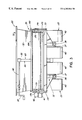
- FIG. 6 is a cross-sectional view shown through a rear portion of a storage hopper of the apparatus and including a hopper outlet means as seen from the line 6 — 6 of FIG. 4, but further showing its relationship to a belt with the belt cartridge in place;
- FIG. 7 is a perspective view as seen from a rear/left hand portion of the complete belt cartridge
- FIG. 8 is a plan view of the belt cartridge of FIG. 7, but with the continuous belt removed for the sake of clarity in illustrating the supporting framework and rollers of the belt cartridge;
- FIG. 9 is a rear view of the belt cartridge as shown in FIG. 8, but on an enlarged scale;
- FIG. 10 is an elevational view of the belt cartridge of FIG. 8, as seen from the left side and on an enlarged scale;
- FIG. 11 is a cross-sectional view as seen from the line 11 — 11 of FIG. 8, but with the continuous belt in place;
- FIG. 12 is a cross-sectional view as seen from the line 12 — 12 of FIG. 8, again with the continuous belt in place and also illustrating the relative position of the cartridge within the front left corner of the chassis structure of the apparatus;
- FIG. 13 is a cross-sectional as viewed from line 13 — 13 of FIG. 1 and on an enlarged scale, and showing a portion of the belt cartridge in relation to the drive motor as mounted in the chassis structure;
- FIG. 14 is an enlarged cross-sectional view as seen from the line 14 — 14 of FIG. 2 and showing the relationship of one form of a rotating brush device with the belt cartridge during operation and mounted in accordance with the attachment system of the present invention;
- FIG. 15 is a rear view of the apparatus of the present invention but showing the attachment of another form of a rotating brush device according to the present invention
- FIG. 16 is an enlarged cross-sectional view as seen from the line 16 — 16 of FIG. 15 and showing the relationship of the rotating brush device of FIG. 15 with the belt cartridge during operation;
- FIG. 17 is a cross-sectional view as seen from the line 17 — 17 of FIG. 16, illustrating a feature of the attachment system of the present invention
- FIG. 18 is a rear view of another form of a broadcasting unit in the form of a twin spinner apparatus also adapted for connection to the apparatus by the attachment system of the present invention.
- FIG. 19 is a side view of the twin spinner apparatus as shown in FIG. 18 .
- the number 20 denotes generally a material spreading apparatus of one embodiment of the present invention, the apparatus 20 having a chassis structure 21 including a lower framework 22 carried on two sets 23 , 23 of wheels.
- the framework 22 has a forwardly extending rigid tongue 24 adapted to be connected to a prime mover or towing device (not shown) such as a tractor.
- a prime mover or towing device such as a tractor.
- Mounted on the tongue 24 is a self contained power unit 25 for producing pressurized hydraulic fluid, the unit 25 including an engine 26 , a pump 27 driven by engine 26 and a hydraulic fluid reservoir 28 .
- An open-topped hopper 30 for containing a supply of the material to be spread is mounted on the chassis near the front thereof and extends substantially across its width.
- Contained within the chassis is a conveyor means 31 which is in the form of a belt cartridge 32 including a continuous belt 33 providing a top or upper flight 34 extending substantially the full length of the chassis and adapted to travel from under the hopper at the front to an open rear end of the chassis structure 21 .
- Attached to the rear of the chassis structure is a material broadcasting unit 35 which is driven to deliver to the ground surface over which apparatus is travelling the material delivered from the hopper 30 to the rear of the chassis structure by the travelling upper flight 34 of the belt cartridge 32 .
- Each set 23 of wheels includes a pair of laterally spaced wheels 36 , 36 mounted for free rotation on a transversely extending axle 37 .
- the two axles 37 , 37 are each intermediately connected independently to the framework 22 by way of a shaft 39 , the axes of which extend in the longitudinal direction of the apparatus 20 and is mounted in the framework in a manner to allow the axles 37 , 37 to independently rock about their longitudinal axes.
- Tires 40 of the wheels 36 are of a low pressure type, and because of the number of wheels and the manner in which the two sets of wheels are able to independently rock, the apparatus 20 is particularly suited for travel on the soft and rolling turfs of golf courses while imparting no tire marks or scuffing thereto.
- the present invention may be incorporated into a self propelled unit including the operator's station, or the apparatus may be produced without wheels, or any other ground supporting means, and modified for mounting on the rear of an existing truck chassis.
- the apparatus 10 may be produced without a self-contained power unit but instead have hydraulic couplings for ready connection to a hydraulic system of the prime mover or of the self propelled unit of which it is a part.
- the motor means 41 , and 42 which separately drive the belt 33 of the belt cartridge 32 and the rotating part of the broadcasting unit 35 , respectively.
- the motor means 42 includes two separate motors which are used in the broadcasting unit but operate in series flow from a single control valve.
- the flow of pressurized hydraulic fluid from pump 27 to the motor means 41 and 42 is governed by the setting of control unit 43 mounted on the chassis structure 21 in front of the hopper 30 and adjacent the power unit 25 .
- the pump 27 draws fluid from the reservoir 28 through line 44 and delivers pressurized fluid to the control unit 43 via line 45 .
- a first control valve (not shown) of the control unit 43 is provided for direction flow from line 45 to a supply line 46 (FIG. 1) extending to motor means 42 of the broadcasting unit 35 .
- a return line 47 extends from motor means 42 back to the control unit 43 .
- a second control valve (not shown) of the control unit 43 receives flow from the return line 47 and may be set to direct a certain portion of the fluid returning from the motor means 41 to a supply line 50 extending to the motor means 41 which provides drive for the continuous belt 33 . Any portion of the returning fluid from motor means 42 not directed to the motor means 41 through supply line 50 is returned by the control unit 43 to the reservoir 28 via a return line 51 . After the fluid supplied via supply line 50 to the motor means 41 passes through the motor, it flows back to the control unit 43 by way of return line 52 and is directed by the control unit back to the reservoir via the return line 51 .
- the amount of material carried from the hopper 30 by the belt 33 is easily adjustable by a hopper outlet means 73 so that normally it would not be necessary to adjust the control valve which redirects a portion of the flow returning from the motor means 42 for the flow to the motor means 41 , or considering the question of speeds of the belt and the broadcasting unit, it may be unnecessary to vary the belt speed in relation to the constant speed of the motor means of the broadcasting unit. It has been further found that as an operator becomes experienced in working with the spreader, it is not difficult to relatively quickly set the speed of travel of the prime mover to accomplish a sufficiently constant application of the material being spread, knowing the setting of the outlet means of the hopper.
- an electronic control component for varying the setting of the proportioning valve which directs fluid through supply line 50 to the motor means 41 of the belt drive.
- Such an electronic control component could respond, for example, to pulses developed by a light reading means or by magnetic pulses activated on each rotation of one of the ground engaging wheels whereby the valve setting for controlling the belt speed relates directly to the rotational speed of a wheel and thus to the ground speed without any turning resistance being experienced by the wheel.
- the hopper 30 of the apparatus 20 which is attached to the top of the chassis structure 21 , is defined by opposed side walls 53 , 53 .
- the two side walls are joined at front edges to opposite ends of a front wall 54 and at rear edges to opposite ends of a rear wall 55 .
- Upper edges of all four walls 53 , 53 , 54 and 55 are disposed in a common horizontal plane which defines the open top of the hopper and through which material may be dumped, for example, by a front end loader. All of the walls converge in a downward direction to an open bottom of the hopper, and bottom edges of the two side walls 53 , 53 and the front wall 54 are in a common plane disposed immediately above a top surface of the upper flight 34 of the continuous belt 33 .
- the chassis structure 21 includes a main upper side panel 56 of rectangular shape provided by a formed sheet metal member 60 and a lower side panel 57 provided by a formed sheet metal member 61 .
- the sheet metal member 61 is bent to provide an inwardly projecting, horizontal flange portion 62
- the sheet metal member 60 is bent to provide an inwardly projecting, horizontal flange portion 63 .
- the sheet metal members 60 and 61 are fastened together with the panels 56 and 57 in the same vertical plane by way of fasteners, such as nuts and bolts 64 passing through engaged flange portions 62 and 63 .
- the opposite side structure of the chassis structure 21 is of identical configuration and of a mirror image to that shown in FIG. 4 .
- the sheet metal member 60 is bent inwardly to form a narrow top portion 65 of the chassis structure 21 , thus providing a top surface 66 along either side of the chassis structure.
- the sheet metal member 61 is then bent downwardly at an angle to form an inwardly and downwardly inclined flange 67 which, as best seen in FIG. 4 corresponds to the incline of the side walls 53 , 53 of the hopper 30 .
- the inwardly inclined flange 67 has a lower edge 68 which is spaced above the top surface of the upper flight 34 of the continuous belt when the belt cartridge 32 is installed, as is more apparent from FIG. 5 .
- an elongated strip such as one formed of rubber material the strip having a lower edge projecting well below the lower edge 68 of the inclined flange 67 so as to form a flexible skirt 71 which engages the upper flight 33 of the continuous belt when the belt cartridge is installed.
- the inclined flange 67 and the flexible skirt 71 prevents the material carried on the upper flight 33 from flowing to the very outer edge of the continuous belt 33 .
- the sheet metal members 60 and 61 forming the two sides of the chassis structure thus provide side walls of the apparatus between which the belt cartridge 32 is located as will be described in more detail below.
- the inclined flanges 67 of the opposed side walls define an open channel behind the hopper 30 and through which the material is carried to the open rear end of the chassis structure 21 .
- Extending between front edges of the side panels 56 of the sheet metal members 60 at the opposite sides of the chassis structure is a front panel 59 of the bulkhead, thus closing off the forward end of the belt cartridge receiving space between the side panels.
- the rear wall 55 of the hopper 30 has the outlet means 73 located at a lower edge 74 thereof (FIG. 6 ).
- the lower edge 74 is at the same level as the top surfaces 66 , 66 of the sides of the chassis structure 21 so that the lower edge 74 is spaced well above the upper flight 34 of the continuous belt 33 .
- Spaced along the lower edge 74 of the rear wall 55 are rearwardly projecting lugs 75 .
- An adjustable gate 76 is part of the outlet means 73 and extends across the width of the chassis structure between the downwardly inclined flanges 67 , 67 of the side walls of the chassis structure.
- the opposite ends of the gate 76 are tapered inward from a top edge of the gate to its lower edge 77 so as to completely close the space below the lower edge 74 of the rear wall 75 .
- a transversely extending rod 80 is integrally affixed to the upper edge of the gate 76 and is held on top of lugs 55 by clamp pieces 81 so that the rod 80 can rotate relative to the lugs 75 and thereby provide a hinge connection 82 between the upper edge of the gate 76 and the lower edge 74 of the rear wall 55 .
- the lower edge 77 ensures a precise shearing of the material and thus an even layer 89 of material being delivered to the rear of the chassis structure (FIGS. 6 ).
- a gate adjustment means 83 is provided for establishing setting of the outlet means 73 of the hopper 30 .
- the gate adjustment means 83 includes a selectively extendible means 84 , which may be in the form of a simple screw jack having a base and housing portion 85 and an extendible rod 86 received in the portion 85 .
- An upper end of the base and housing portion 85 is pivotally connected by a bracket 88 (FIG. 1) to the rear wall 55 well above the gate 76 , and a lower end of the extendible rod 86 is connected to a rear surface of the gate 76 by a pivot connection 79 .
- crank handle 87 is readily accessible to an operator at the left hand side of the hopper 30 and is connected to and outer end 92 of a crank extension 90 , which, at its other end is attached to a screw portion in the base and housing portion 84 .
- the crank extension 90 is carried by the hopper for rotation in a mounting bracket 91 .
- the extendible means is shortened, i.e., extendible rod is pulled upwardly into the base and housing portion 85 , while rotation of the crank handle 87 in the opposite direction extends the rod 86 .
- extendible rod 86 is retracted or extended, as indicated by arrow B in FIG.
- the gate 76 which is hinged about the axis of rod 80 , swings as indicated by arrow C, so as to selectively vary the amount of material which passes thereunder in the form of layer 89 .
- One outer end of the rod 80 which is affixed to the gate 76 , extends laterally outward of the side panel 56 , and has fastened thereto at right angles to the longitudinal axes of the rod 80 an indicator member 93 . Accordingly, when the gate 76 is raised or lowered, as indicated by the arrow C, the indicator member 93 , which can be readily observed, is rotated with the gate, thus giving a visual indication as to the setting of the gate 76 .
- FIGS. 7 to 13 which illustrate belt cartridge 32 , which is readily insertable and removable from the chassis structure 21 , as will become more understandable from the following description, it may be noted that FIG. 7 shows the complete belt cartridge in a removed condition.
- the continuous belt 33 which has the upper flight 34 extending substantially the fill length of the belt cartridge, is provided with a plurality of ribs 94 , which may be in the form of various patterns, but should extend at least partially in a transverse direction so as to drag the material to be distributed from a pile of the material contained in the hopper 30 , as the upper flight 34 is driven in a direction from front to rear of the apparatus 20 .
- the belt cartridge 32 includes a framework 95 having side rails 100 and 101 which carry therebetween a drive roller 96 at the rear, a belt tensioning roller 97 at the front and a connecting table structure 98 positioned between the rollers for supporting the upper flight 34 .
- the side rail 100 is an elongated sheet steel member of generally L-shaped configuration having a vertical web portion 102 and an inturned horizontal bottom flange 103 .
- At the forward end of the side rail 100 there is an inturned end flange 104 , and affixed to the rear end of the side rail is an abutment plate 105 disposed in a plane normal to the longitudinal axis of the side rail 100 .
- the vertical length of the abutment plate 105 is greater than the height of the side rail 100 , and it extends slightly below the bottom surface of the flange 103 of the side rail. It is also of a sufficient height to extend well above the top edge of side rail 100 so that an upper edge of the abutment plate substantially coincides with the level of the top portion 65 of the sheet metal member 60 of the chassis structure when the belt cartridge 32 is installed as illustrated in FIG. 5 .
- Adjacent a lower part of the abutment plate 105 Adjacent a lower part of the abutment plate 105 , a rearward projecting post 106 is affixed to a flat rear surface 163 of the abutment plate 105 .
- shaped side projections 112 are provided adjacent the rear end of the side rail 100 , but the projections 112 are provided with threading bores 113 for receiving mounting bolts of the motor means 41 .
- the vertical web of the rail is provided with an opening 115 through which a drive shaft 114 of the drive roller 96 projects.
- the mounting plate 116 Secured to an inner surface of the vertical web portion 102 of the rail, but spaced slightly inward therefrom is an elongated mounting plate 116 .
- the mounting plate 116 which is in parallel relationship to the web portion 102 has a plurality of holes along its length for receiving fastening bolts 117 .
- the web portion 102 has a plurality of holes which form bolt access openings 118 through the web portion, the access openings being aligned with the bolt receiving holes 117 in the mounting plate 16 .
- the side rail 101 is a mirror image of the structure of side rail 100 except the side projections corresponding to projection 112 of the side rail 100 are not provided with threaded bores and there is no opening corresponding to opening 115 of the side rail 100 .
- the table structure 98 which is bolted between side rails 100 and 101 , includes a flat, sheet metal, horizontal, top plate portion 120 with downwardly depending front flange 121 and rear flange 122 . At opposite sides of the top plate portion 120 there are provided downwardly depended side flanges 123 (FIG. 11) which are provided with threaded openings 124 for alignment with the holes of the mounting plate 116 so that bolts 117 extending through the holes of the mounting plate 116 can be threaded into the threaded openings 124 thereby supporting the table structure 98 between the mounting plates 116 of the side rails 100 and 101 .
- a cover plate 126 which is of substantially the width of continuous belt 33 but is of less width than the top plate portion 120 .
- the cover plate 126 across which the upper flight 34 of the continuous belt 33 is drawn, is preferably formed of a high wear resistant material having a surface providing a low coefficient of friction, such as a polyethylene plastic of the ultra high molecular weight type.
- the cover plate 126 is formed with a plurality of large circular openings, as shown at 127 , extending therethrough. The openings 127 compensate for the different expansions experienced by the plastic material and the steel in the top plate portion 120 due to a temperature rise during operation. Moreover, such openings have been found to reduce the drag of the upper flight over the cover plate.
- the tensioning roller 97 is mounted for rotation on a stationary shaft 130 extending between side rails 100 and 101 forward of the front flange 121 of the table structure 98 (FIGS. 11 & 12 ).
- Each end portion 131 of the shaft 130 is received between a lower horizontal rib 132 and an upper horizontal rib 133 which are both formed integrally with an inner surface of the side rail 100 , 101 and thereby form a horizontal channel 134 extending in the longitudinal direction of the rail.
- a threaded opening 135 is provided through each end portion 131 of the shaft 130 and receives a bolt 136 which passes through a bore in inturned end flange 104 at the forward end of the associated side rail 100 , 101 .
- the bolts 136 can be turned from the front end of the belt cartridge to allow the end portion of the shaft to move in the channels 134 of each side rail towards the rear of the cartridge or alternatively, to be pulled forward.
- a hub 137 which has a central bore defining a bearing seat 140 .
- a bearing 141 is thus installed between the hub 137 and the shaft 130 (FIG. 12 ).
- a spacer sleeve 142 is provided between an inner bearing race of the bearing 141 and the ribs 132 and 133 to maintain the roller 97 in a centered position between the side rails 100 , 101 .
- the continuous belt 30 is formed of general flat material having the raised ribs 94 on the outer surface, there are vulcanized on the flat inner surface 146 thereof adjacent each side edge 143 of the continuous belt, an internal ridge 144 , an inner side surface 145 facing an outer end surface 147 of the hub 137 .
- the inner side surface 145 slants outwardly toward the inner flat surface 146 of the belt and in a direction towards the outer end of the hub.
- the outer end surface 147 of the hub extends to the circumference of the roller, the end surface 147 tapering outwardly and toward the end of the roller 97 so as to approximately coincide with the taper of the adjacent inner side surface of the ridge.
- the inner side surface 145 of the ridge thus provides an abutment surface inwardly of the inner surface 146 of the continuous belt for engagement with an abutment surface provided by end surface 147 at the end of the roller so that in the event the continuous belt 33 tracks slightly sideways, i.e., the adjacent edge 143 approaches the end of the roller, the abutment surfaces engage to limit the sideways tracking of the belt.
- the drive roller 96 is mounted on a shaft 150 jouralled for rotation relative to side rails 100 , 101 .
- a roller hub 151 is provided at each end of the roller 96 and is secured to both the roller 96 and the shaft 150 so that the shaft 150 and roller 96 rotate as a unit.
- the hub 151 provides an outer end surface 152 of the same shape as the outer end surface 147 of the hub 137 in the tensioning roller so as to enhance the self-tracking feature of the continuous belt 33 .
- a bearing retaining flange 153 Surrounding the opening 115 of rail 100 on the inside of its vertical web portion 102 of rail 100 is a bearing retaining flange 153 which contains bearing a 154 thus allowing rotation of the outer end 155 of the shaft 150 .
- Hub 151 includes an outer end portion 156 of smaller diameter which is adapted to engage an inner race of the bearing 154 so as to control the end play of the roller 96 .
- the outer end 155 of the shaft 150 extends through the opening 115 of the rail and an opening 157 in the side panel 56 of the sheet metal member 60 forming the chassis structure 21 .
- the motor means 41 which is preferably in the form of a hydrostatic motor, is provided with a pair of opposed attachment flanges having openings therethrough for alignment with threaded openings 113 , 113 of slide blocks 112 , 112 formed on the web 102 of the side rail 100 .
- the motor means 41 is thereby attached to the side rail 100 by way of bolts which pass through the holes in the attachment flanges of the motor means and are threaded into opening 113 , 113 .
- the outer end 155 of the shaft 150 projects into a bore of a rotor of the motor means sized to receive the shaft 150 .
- the shaft 150 and the rotor are provided with keyways so as to be drivingly connected together.
- FIGS. 4, 5 and 7 it can be seen that by two people grasping opposite sides of the free belt cartridge 32 , it can be readily lifted and inserted into the rear of the chassis structure 21 .
- the front end is first raised and moved forward until the forward end of the side rails 100 , 101 rest on the ledge provided on either side by flanges 62 , 63 , i.e., with the bottom surfaces of the bottom flanges 103 of the side rail 100 and 101 resting on the upper surface of flange 63 .
- the side blocks 107 , 107 at the front of each side rail are in close proximity to the interior surface of the side panel 56 of the chassis structure and thus permit substantially no side movement of the belt cartridge.
- the interior belt cartridge 32 can be easily pushed to its forward-most position where the front ends of the rails are brought against the front panel 59 of the bulkhead, and at which time the front surfaces of the plates 105 , 105 are juxtaposed the rear edges of the sheet metal members 60 , 61 forming the side panels 56 , 57 , the ledge provided by the flanges 62 , 63 and the inturned upper portion of the sheet metal members.
- the motor means 41 can be attached to the belt cartridge through opening 157 in the side panel 56 by way of bolts 160 , 160 .
- the reactionary force to the top flight 34 of the continuous belt 33 dragging the material from beneath a pile of the material in the hopper results in a continuous push of the belt cartridge to its normal forward most position.
- the belt tensioning can be readily adjusted by turning bolts 136 , 136 .
- the entire unit can be completely disassembled by reducing the tension by turning bolts 136 , 136 , removing the three bolts 117 , which can be readily turned out through belt access opening 118 in the web 102 of the side rail 100 or 101 .
- the continuous belt 33 can be slid sideways from the rollers 96 , 97 and all of the other parts separated as required.
- the material broadcasting unit 35 in the apparatus 20 as illustrated in FIGS. 1 to 3 is further shown in FIG. 14, and in the latter figure its manner of operation in relation to broadcasting material received from continuous belt 33 is not unlike the operation of brush devices provided on known top dressers.
- the brush device appearing as the material broadcasting unit 35 is provided with a framework 162 which allows for quick substituting for other units described below due to a particular attachment system involving features of the chassis structure 21 and belt cartridge 32 as well.
- the belt cartridge 32 provides abutment plates 105 , 105 at the rear ends of side rails 100 , 101 , and when the belt cartridge 32 is in the installed position, these abutment plates have rear surfaces 163 , 163 thereof in a common vertical transverse plane at the very rear of the chassis structure 21 as defined by formed sheet metal members 60 and 61 .
- the posts 106 of each side rail project rearwardly from the rear surfaces 163 , 163 .
- the attachment system of the present invention includes an attachment component 164 mounted on top of the chassis structure 21 at either side of the very rear of the chassis structure 21 as is readily apparent in FIGS. 4 and 16.
- the attachment component 164 has an upper portion above the top surface 66 defined by the top portion 65 of the formed sheet metal member 60 , the upper portion of the component 164 being a U-shaped clevis portion 165 formed integrally with a downwardly projecting threaded shank 166 .
- Upwardly extending lugs 167 , 167 forming each clevis portion 165 have aligned transverse bores 168 , 168 therethrough and receive a cross pin 170 thereby providing a transversely extending member.
- each sheet metal member 60 has an opening through which the shank 166 of one of the components 164 extends, there being affixed to the lower surface of the top portion 65 a threaded nut portion 171 into which the shank portion 166 is screwed. It can be seen by simply turning the clevis so that it threads into or out of the nut portion 171 , the height of the cross pin above the top side surface 66 can be adjusted.
- the framework 162 of the brush device forming broadcasting unit 35 includes a pair of side members 172 and 173 which may be made of flat metal plates having bearing means 174 for rotatably mounting a shaft 175 of a rotatable brush 176 at opposite ends thereof One end of the shaft 175 is drivingly connected to the motor means 42 externally of the side member 172 .
- the rotatable brush 176 has a cylindrical core member 177 which is affixed to shaft 175 so as to be rotated in the direction of arrow D in FIG. 14 .
- the rotatable brush has multiple radially projecting bristles 179 affixed to the cylindrical core member 177 , and the outer ends of the bristles form a generally cylindrical outer surface of the brush having a length substantially equal to the width of the continuous belt 33 .
- each plate member forming the side members 172 , 173 extends upwardly from the rear-most part of the side member to the highest portion of the side member and then slopes downwardly to the forward-most part of the side member.
- the side member has vertical front edge 180 extending substantially to the bottom of the side member.
- each side member 172 and 173 Affixed to the front edge 180 of each side member 172 and 173 in front of the main body portion of the unit is an abutment plate 181 , the front faces of the two abutment plates being a common vertical transverse plane.
- An upwardly extending slot 183 which curves slightly forward is provided in a lower edge 182 in the portion of each of the side members 172 , 173 , which edge extends rearwardly under the forward-most portion of the side members 172 , 173 .
- a cross bar 184 which is connected between the upper-most portion of the side members 172 , 173 .
- Located immediately below the upwardly slanting top edge of each side member 172 , 173 is an elongated opening 185 which provides a hand-hold at each end of the device.
- the upper end of slot 183 is forward of the front faces of the abutment plates 181 a horizontal distance equal to the distance between the rear faces 163 of the abutment plates 105 of the belt cartridge when carried in place by the chassis structure 21 . Accordingly, to install the broadcasting unit 35 , it is lifted from opposite ends so as to hold the upper portion of the unit slightly forward when placing the hook-shaped, upper forward portions of the side members over the cross pins 170 of the attachment component 164 above the top side surfaces 66 of the chassis structure 21 . As it is lowered into place and released, the abutment plates 181 , 181 of the unit 35 swing into full contact with the vertically disposed abutment plates 105 , 105 carried at the rear of the chassis structure 21 .
- the unit 35 hangs naturally in its proper position with the abutment plates 181 , 181 engaging the abutment plates 105 , 105 .
- the effective outer cylindrical surface of the brush formed by the outer ends of the bristles passes in close proximity to the surface of the continuous belt 33 at the point where the continuous belt commences to round the drive roller 96 at the very rear-most of the conveyor means 31 .
- the outer ends of the bristles 179 may slightly brush the outer surface of the continuous belt 33 at this point on rotation of the brush.
- the layer 89 of material approaches the rear end of the upper flight 34 and starts to drop off, it is engaged by the bristles 179 and propelled downwardly and slightly rearward so as to strike turf 189 over which the apparatus 20 is passing.
- the apparatus 20 spreads the material evenly over a track which is approximately the width of the continuous belt 33 .
- the bristles may become sufficiently worn that it becomes desirable to lower the rotatable brush 176 .
- Adjustment of the position of the brush can be readily accomplished by rotating the attachment component 164 with the side members 172 and 173 of the unit 35 raised to clear the cross pin 170 .
- the brush device shown as broadcasting unit 35 a in FIGS. 15 and 16 it may first be seen that it has a framework 162 a shaped somewhat different than described for broadcasting unit 35 above, but with respect to the parts thereof which cooperate with the attachment system of the chassis 21 and the belt cartridge 32 carried thereby, it has substantially identical characteristics.
- the rotatable member, hereinafter referred to as a rotatable brush 176 a of the broadcasting unit 35 a is located lower than the rear end of the belt cartridge 32 , i.e., the rotatable brush is located under the drop-off end of the continuous belt 33 .
- the rotatable brush 176 a is rotated in the opposite direction so that the material from layer 89 falls from the upper flight 34 as the continuous belt 33 rounds the drive roll 96 , and the falling material, as it is struck by bristles at the upper periphery of the rotating brush, it is propelled rearwardly of the brush and somewhat upwardly as indicated in FIG. 16 .
- the framework again includes two parallel side members 172 a and 173 a with the rotatable brush 176 , driven by motor means 41 , mounted therebetween. Because the roller is mounted considerably lower relative to the remainder of the apparatus than in the case of broadcasting unit 35 , the side members 172 a , 173 a have greater depth.
- the side members 172 a , 173 a have however, an upper-most portion which extends forwardly of a front vertical edge 180 a and provide a lower edge 182 a extending rearwardly from the forward portion and including an upwardly extending slot 183 a .
- the upwardly extending slot 183 a preferably curves forward slightly for reasons described in more detail below.
- each side member 180 a Affixed to the front vertical edge 180 a of each side member 180 a is an abutment plate 181 a, front faces of the abutment plates of the two side members 172 a , 173 a being in a common transversely extending, vertical plane. As shown the rear edge of the side members 172 a , 173 a slants downwardly and rearwardly and at the wider lower portion of each side members there is provided a hand-hold opening 185 a.
- the center of gravity of the broadcasting unit 35 a is rear of cross pin 170 when the broadcasting unit 35 a is suspended by the top of the slot 183 a resting on the cross pin 170 .
- the unit is held with the upper-most portion slanting somewhat forward to hook the slot over the cross pin 170 , and the main lower portion of the unit is swung down so that front surface of the abutment plates 181 a , 181 a engage rear surface 163 , 163 of the abutment plates 105 , 105 exposed at the rear of the sides of chassis structure 21 .
- the broadcasting unit is urged into its seating position due to its center of gravity being rear of the contact of the upper most part of the side members 172 a , 173 a with the cross pin 170 . Because of the slight forward curvature of the slot straight, upward movement of the unit is resisted by engagement of the forward edge of the slot below the cross pin.
- the post 106 which is affixed to the rear abutment plate 105 carried by the belt cartridge, projects rearwardly of the rear surface 163 of the abutment plate 105 and provides a safety lock 186 permitting limited vertical movement of the broadcasting unit 35 a while preventing the pair of abutment plates 18 la from swinging rearwardly out of contact with the pair of abutment plates 105 .
- each of the abutment plates 181 a , 181 a of the framework 162 a is provided with an elongated slot 187 which is positioned to allow post 106 to project therethrough when the abutment plates 181 a , 181 a come into engagement with the abutment plates 105 , 105 .
- transverse bores Near the rear end portion of the posts 106 , there are provided transverse bores, each adapted to receive an easily insertable and removable clip pin 190 .
- the clip pin 190 is inserted through a transverse bore 188 in the post 106 on either side of the apparatus, whereby any significant jars encountered by the apparatus ensures the unit 35 a cannot depart from the apparatus 20 .
- the slot 187 is elongated in the vertical direction, there is permitted limited vertical adjustment of the relative positions of the abutment plates 181 a , 181 a and abutment plates 105 , 105 as would occur on adjustment of the locating of the cross pin 170 in the attachment component 164 .
- all of the different forms of broadcasting units as described herein, or other alternative forms which may be developed for use with the quick attachment system of the present invention may be provided with the above described safety lock 186 .
- the framework 162 a includes sub-frame members 191 and 192 , attached to and depending from side members 172 a and 173 a , respectively. These sub-frame members are provided with bearings in which shaft 193 of the rotatable brush 176 a is journalled for rotation. One end of shaft 193 extending through sub-frame member 191 and is attached to the output of motor means 42 so as to be driven for rotation, the motor means 42 being attached to the sub-frame 191 .
- rotatable brush 176 a is of a character significantly different from that of rotatable brush 176 described above, in that the bristles thereof are arranged in a specific pattern.
- the rotatable brush 176 a is provided with a core member 194 affixed to shaft 193 for rotation therewith.
- the bristles are arranged with the bases of the bristles affixed to an outer surface 195 of the core member 194 along narrow paths or strips to form flights 196 and 197 of bristles which spiral around the core member 194 .
- the movement of the upper periphery of the imaginary cylindrical form containing the bristles is rearwardly so as to distribute the material slightly upwardly and rearwardly as previously described.
- the strips of bristles are spiraled in opposite directions from a mid-area of the rotating brush towards opposite ends thereof.
- the effect of the flights of bristles is to progress from the centre outwardly towards the opposite ends of the rotated brush 176 a .
- the inner ends of the oppositely directed flights 196 and 197 are separated at the mid-area of the rotatable brush 176 a by short strip 198 of bristles.
- the inner ends of flights 196 and 197 begin at opposite ends of strip 198 .
- the short strip 198 of bristles does not spiral but extends in the longitudinal direction of the rotatable brush 176 a .
- a pair of short strips 198 of bristles disposed at 180 degrees about the circumference of the outer surface 195 of the core member 194 , and each of the oppositely directed flights 196 and 197 consist of a co-existing pair of flights 196 ′ & 196 ′′ and 197 ′ & 197 ′′, respectively, which remain constantly spaced in the progression from the center towards the outer ends.
- Flights 196 ′ and 197 ′ commence at opposite ends of one short path 198 of bristles, and flights 196 ′′ and 197 ′′ commence at opposite ends of the other short path 198 .
- the nature of spreading achieved by the location and design of rotating brush 176 a is significantly different than that of the standard rotating brush 176 described above.
- the effect of the outwardly travelling flights 196 and 197 is to impart a direction of travel of the particles of material falling from the upper flight 34 of the continuous belt 33 not only rearwardly and/or slightly upwardly but also slightly side ways as depicted at 99 in FIG. 15 .
- the exception to this is at the central portion of the brush where the short paths 198 of bristles tend to expell the particles mainly upwardly and rearwardly so as to distribute material to the middle of the path of travel. This results in the even spreading of a path on the turf slightly wider than the length of the brush.
- the top dressing can be carried out with fewer passes, and because the width of the path is slightly greater than the wheel tracks of the machine, it is unnecessary to overlap the tire tracks during successive passes and thereby decrease damage to the turf grass surface.
- the design of the rotatable brush 176 a has good distribution characteristics on a number of varied materials such as sand, soil, compost, wood chips and gravel. It is further capable of equally well broadcasting light or heavy applications. The material can be spread very lightly up and into the air, thus creating a dusting condition of material which has been found to effectively penetrate the turf canopy making the material almost invisible to the eye, causing less tracking, and providing much better mowing conditions.
- bristles While in relation to the description of the rotatable brush 176 a there has been described the provision of strips of bristles, it is apparent that elements other than bristles may be used. For example, such elements may be in the form of relatively stiff narrow plastic strips. Alternatively, the spiralling strip of bristles could be replaced with a continuous spiralling strip of flat rubber material, or even a spiral metal strip. However, elements in the form of bristles appear practical insofar as wear characteristics are concerned and the bristles do not adversely affect granular material such as fertilizer particles.
- the strips in the described spiralling pattern may not be continuous, or indeed spiral, to obtain only the desired upwardly and rearwardly travel of the material under some conditions.
- an arrangement as shown in FIG. 15 has definite advantages.
- the broadcasting unit 35 b shown in FIGS. 18 and 19 is in the form of a twin spinner, which is capable of distributing material on a much wider path.
- the broadcasting unit 35 b is again provided with a framework 162 b adapted for attachment to the apparatus 20 provided with quick attachment features allowing the unit 35 b to be connected to an operative position at the rear of the apparatus 20 in a period of a few minutes without the requirement of any tools.
- a framework 162 b of the broadcasting unit 35 b again includes side members 172 b , 173 b , each having a forward upper portion which is provided with an upwardly extending slot 183 b .
- the forward vertical edges of the side members 172 b , 173 b have a continuous abutment plate 181 b attached thereto for engagement with the rear faces 163 , 163 of the abutment plates 105 , 105 .
- Properly located elongated slots 187 , 187 are provided at opposite ends of abutment plate 181 b for reception of posts 106 , 106 so as to provide a safety lock 186 in the attachment system.
- a compound hopper 200 Suspended from side members 172 b and 173 b is a compound hopper 200 having an upper forward edge 201 adapted to be located below and forward of the rear end of the belt cartridge 32 , so that all of the material being discharged from the upper flight 34 is collected in the compound hopper 200 .
- the compound hopper is divided into two separate downwardly converging compartments 202 positioned to each receive one half of the collected material, and each compartment 202 having a bottom opening 203 .
- Protruding from the upper rear edge of the compound hopper 20 is a pair of spaced handles 209 , 209 providing hand-hold openings near opposite ends of the hopper for convenience in mounting and removing the twin spinner apparatus forming broadcasting unit 35 b .
- a pair of twin spinner units 205 , 205 Carried below the compound hopper 200 by a downwardly depending sub-frame member 204 is a pair of twin spinner units 205 , 205 each driven by an independent motor means 42 b , 42 b driven in series by fluid delivered from hydraulic supply line 46 .
- the units 205 , 205 each include a circular, rotatable delivery plate 206 mounted on a common axes of the output of the motor means 42 b , 42 b and drivingly connected thereto.
- a shield 208 encircles a portion of the forward edge of the circular plate.
- each delivering plate 206 is provided with a plurality of affixed, radially extending paddle members 207 which engage the material falling through the bottom openings 203 , 203 of the two compartments 202 , 202 and thereby flings the particles of the material out through the side and rear open area behind the shield 208 .
- axes F,F, of rotation of the delivering plates 206 are in a common vertical transverse plane, as viewed in FIG. 19, the axes F,F of rotation of the delivering plates do in fact converge slightly towards each other in that plane, as can be seen from the rear view of FIG. 18 .
- Such an arrangement enhances the side-ways range of distributing from the broadcasting unit 35 b of the present invention.
Landscapes
- Life Sciences & Earth Sciences (AREA)
- Soil Sciences (AREA)
- Environmental Sciences (AREA)
- Engineering & Computer Science (AREA)
- Architecture (AREA)
- Civil Engineering (AREA)
- Structural Engineering (AREA)
- Road Paving Machines (AREA)
Abstract
Description
Claims (17)
Priority Applications (2)
| Application Number | Priority Date | Filing Date | Title |
|---|---|---|---|
| US09/243,113 US6202944B1 (en) | 1999-02-03 | 1999-02-03 | Material spreading apparatus |
| US09/793,112 US20010006196A1 (en) | 1999-02-03 | 2001-02-27 | Material spreading apparatus |
Applications Claiming Priority (1)
| Application Number | Priority Date | Filing Date | Title |
|---|---|---|---|
| US09/243,113 US6202944B1 (en) | 1999-02-03 | 1999-02-03 | Material spreading apparatus |
Related Child Applications (1)
| Application Number | Title | Priority Date | Filing Date |
|---|---|---|---|
| US09/793,112 Continuation US20010006196A1 (en) | 1999-02-03 | 2001-02-27 | Material spreading apparatus |
Publications (1)
| Publication Number | Publication Date |
|---|---|
| US6202944B1 true US6202944B1 (en) | 2001-03-20 |
Family
ID=22917404
Family Applications (2)
| Application Number | Title | Priority Date | Filing Date |
|---|---|---|---|
| US09/243,113 Expired - Fee Related US6202944B1 (en) | 1999-02-03 | 1999-02-03 | Material spreading apparatus |
| US09/793,112 Abandoned US20010006196A1 (en) | 1999-02-03 | 2001-02-27 | Material spreading apparatus |
Family Applications After (1)
| Application Number | Title | Priority Date | Filing Date |
|---|---|---|---|
| US09/793,112 Abandoned US20010006196A1 (en) | 1999-02-03 | 2001-02-27 | Material spreading apparatus |
Country Status (1)
| Country | Link |
|---|---|
| US (2) | US6202944B1 (en) |
Cited By (27)
| Publication number | Priority date | Publication date | Assignee | Title |
|---|---|---|---|---|
| US6508419B1 (en) | 1998-09-03 | 2003-01-21 | Turfco Manufacturing, Incorporated | Broadcast spreading top dresser |
| US6517281B1 (en) * | 2000-05-19 | 2003-02-11 | Highway Equipment Company | Adjustable spinner for a particulate material spreader |
| US6533198B1 (en) * | 1999-11-16 | 2003-03-18 | The Toro Company | Top dresser |
| US6817552B2 (en) | 2002-02-06 | 2004-11-16 | Turfco Manufacturing, Inc. | Broadcast spreading top dresser |
| US6932286B2 (en) | 2001-11-07 | 2005-08-23 | Fred P. Smith | Combination drop and broadcast spreader |
| US20050242124A1 (en) * | 2004-04-28 | 2005-11-03 | Turfco Manufacturing, Inc. | Top dresser |
| US20090191034A1 (en) * | 2007-12-27 | 2009-07-30 | Ty-Crop Manufacturing Ltd. | Remote controllable material handling system |
| FR2926825A1 (en) * | 2008-01-29 | 2009-07-31 | Synergil Soc Par Actions Simpl | Particle material e.g. ice melting salt, distributing device i.e. public road maintenance device, for motor vehicle, has conveyor extending to base of storage bunker whose opening is in form of slit transversely extending to conveyor |
| FR2926826A1 (en) * | 2008-01-29 | 2009-07-31 | Synergil Soc Par Actions Simpl | Particle material e.g. ice melting salt, distributing device i.e. public road maintenance device, for motor vehicle, has storage bunker mounted on support chassis and fixed to base chassis based on three different positions along conveyor |
| US7980484B1 (en) | 2008-04-21 | 2011-07-19 | Highway Equipment Company | Automatic flow gap adjusting anti-slab method and apparatus |
| US9010665B1 (en) | 2012-03-15 | 2015-04-21 | Earth & Turf Products, Llc | Manually operated compost topdresser |
| CN105421196A (en) * | 2015-12-17 | 2016-03-23 | 浙江美通筑路机械股份有限公司 | Vehicular spreader of solid road binder |
| FR3032981A1 (en) * | 2015-02-20 | 2016-08-26 | Rabaud Sa | BUCKET FOR RECEIVING AND DISPENSING GRAIN OR POWDER PRODUCT, IN PARTICULAR SALT OR SAND |
| US9491902B1 (en) | 2013-02-06 | 2016-11-15 | Turfco Manufacturing, Inc. | Broadcast spreading top dresser for sand |
| FR3040255A1 (en) * | 2015-09-02 | 2017-03-03 | Sulky Burel | DOSING DEVICE FOR PARTICLE DISTRIBUTION SYSTEM FOR AGRICULTURAL MACHINE, AND CORRESPONDING DISTRIBUTION SYSTEM. |
| US9585306B1 (en) | 2012-01-13 | 2017-03-07 | Shane Pike | Dual chain fertilizer spreader for golf courses |
| US20170274397A1 (en) * | 2011-10-17 | 2017-09-28 | Highway Equipment Company | Broadcast spreader with swath manipulation |
| CN109757180A (en) * | 2019-03-06 | 2019-05-17 | 安徽徽宝农林科技有限公司 | A kind of thunder bamboo shoot plantation fertilizer apparatus of vernalization fertilizer |
| US10729063B2 (en) | 2009-02-02 | 2020-08-04 | Deere & Company | Seeding machine with seed delivery system |
| USD920387S1 (en) * | 2019-05-10 | 2021-05-25 | Conestoga Manufacturing, LLC | Pull-type topdresser compost spreader |
| USRE48572E1 (en) | 2009-02-02 | 2021-06-01 | Deere & Company | Planting unit for a seeding machine having blocking member to control hand-off of seed from a seed meter to a seed delivery system |
| US11051445B2 (en) | 2018-06-27 | 2021-07-06 | Deere & Company | Seeding system |
| US11058047B2 (en) | 2018-06-27 | 2021-07-13 | Deere & Company | Seeding system |
| US11064649B2 (en) | 2018-06-27 | 2021-07-20 | Deere & Company | Seeding system |
| US20220355334A1 (en) * | 2021-05-04 | 2022-11-10 | Unverferth Manufacturing Co., Inc. | Dry Product Spreader |
| US20240167234A1 (en) * | 2022-11-18 | 2024-05-23 | Stabilcorp Pty Ltd | Spreader Assembly |
| US12514148B2 (en) | 2011-03-25 | 2026-01-06 | Deere & Company | Planting unit for a seeding machine having a seed meter and seed delivery system |
Families Citing this family (1)
| Publication number | Priority date | Publication date | Assignee | Title |
|---|---|---|---|---|
| US20050165521A1 (en) * | 2004-01-27 | 2005-07-28 | Gruhn Steve S. | Precision turf treatment |
Citations (8)
| Publication number | Priority date | Publication date | Assignee | Title |
|---|---|---|---|---|
| US927141A (en) * | 1908-02-20 | 1909-07-06 | Leslie S Hackney | Manure-spreader. |
| DE404141C (en) * | 1923-02-18 | 1924-10-14 | Mueller Wilhelm | Differential gear with acting on the eccentrics of the drive shaft rollers, especially for motor vehicles |
| US3097851A (en) * | 1960-11-28 | 1963-07-16 | Arthur H Cohrs | Dirt metering and spreading machine |
| US4124167A (en) * | 1977-04-11 | 1978-11-07 | Coleman Robert E | Material spreader for mounting on a vehicle |
| US4438873A (en) | 1981-10-28 | 1984-03-27 | Turfco Manufacturing, Inc. | Ground driven top dresser utilizing special clutch mechanism |
| SU1447309A2 (en) * | 1987-06-29 | 1988-12-30 | Всероссийский научно-исследовательский и проектно-технологический институт химизации сельского хозяйства | Machine for application of fertilizers |
| US5307952A (en) | 1991-02-06 | 1994-05-03 | Turfco Manufacturing Incorporated | Top dresser |
| US5307965A (en) | 1992-11-30 | 1994-05-03 | Turfco Manufacturing, Incorporated | Ground-driven top dresser utilizing easily actuated clutch mechanism |
-
1999
- 1999-02-03 US US09/243,113 patent/US6202944B1/en not_active Expired - Fee Related
-
2001
- 2001-02-27 US US09/793,112 patent/US20010006196A1/en not_active Abandoned
Patent Citations (9)
| Publication number | Priority date | Publication date | Assignee | Title |
|---|---|---|---|---|
| US927141A (en) * | 1908-02-20 | 1909-07-06 | Leslie S Hackney | Manure-spreader. |
| DE404141C (en) * | 1923-02-18 | 1924-10-14 | Mueller Wilhelm | Differential gear with acting on the eccentrics of the drive shaft rollers, especially for motor vehicles |
| US3097851A (en) * | 1960-11-28 | 1963-07-16 | Arthur H Cohrs | Dirt metering and spreading machine |
| US4124167A (en) * | 1977-04-11 | 1978-11-07 | Coleman Robert E | Material spreader for mounting on a vehicle |
| US4438873A (en) | 1981-10-28 | 1984-03-27 | Turfco Manufacturing, Inc. | Ground driven top dresser utilizing special clutch mechanism |
| SU1447309A2 (en) * | 1987-06-29 | 1988-12-30 | Всероссийский научно-исследовательский и проектно-технологический институт химизации сельского хозяйства | Machine for application of fertilizers |
| US5307952A (en) | 1991-02-06 | 1994-05-03 | Turfco Manufacturing Incorporated | Top dresser |
| US5478104A (en) | 1991-02-06 | 1995-12-26 | Turfco Manufacturing, Incorporated | Cantilevered leaf spring assembly |
| US5307965A (en) | 1992-11-30 | 1994-05-03 | Turfco Manufacturing, Incorporated | Ground-driven top dresser utilizing easily actuated clutch mechanism |
Cited By (38)
| Publication number | Priority date | Publication date | Assignee | Title |
|---|---|---|---|---|
| US6508419B1 (en) | 1998-09-03 | 2003-01-21 | Turfco Manufacturing, Incorporated | Broadcast spreading top dresser |
| US6533198B1 (en) * | 1999-11-16 | 2003-03-18 | The Toro Company | Top dresser |
| US9206563B1 (en) | 2000-05-19 | 2015-12-08 | Highway Equipment Company | Adjustable spinner for a particulate material spreader |
| US6517281B1 (en) * | 2000-05-19 | 2003-02-11 | Highway Equipment Company | Adjustable spinner for a particulate material spreader |
| US20030192967A1 (en) * | 2000-05-19 | 2003-10-16 | Highway Equipment Company | Adjustable spinner for a particulate material spreader |
| US6932286B2 (en) | 2001-11-07 | 2005-08-23 | Fred P. Smith | Combination drop and broadcast spreader |
| US20060006256A1 (en) * | 2001-11-07 | 2006-01-12 | Smith Fred P | Combination drop and broadcast spreader |
| US6817552B2 (en) | 2002-02-06 | 2004-11-16 | Turfco Manufacturing, Inc. | Broadcast spreading top dresser |
| US20050242124A1 (en) * | 2004-04-28 | 2005-11-03 | Turfco Manufacturing, Inc. | Top dresser |
| US7347320B2 (en) * | 2004-04-28 | 2008-03-25 | Turfco Manufacturing, Inc. | Top dresser |
| US20090191034A1 (en) * | 2007-12-27 | 2009-07-30 | Ty-Crop Manufacturing Ltd. | Remote controllable material handling system |
| FR2926825A1 (en) * | 2008-01-29 | 2009-07-31 | Synergil Soc Par Actions Simpl | Particle material e.g. ice melting salt, distributing device i.e. public road maintenance device, for motor vehicle, has conveyor extending to base of storage bunker whose opening is in form of slit transversely extending to conveyor |
| FR2926826A1 (en) * | 2008-01-29 | 2009-07-31 | Synergil Soc Par Actions Simpl | Particle material e.g. ice melting salt, distributing device i.e. public road maintenance device, for motor vehicle, has storage bunker mounted on support chassis and fixed to base chassis based on three different positions along conveyor |
| US7980484B1 (en) | 2008-04-21 | 2011-07-19 | Highway Equipment Company | Automatic flow gap adjusting anti-slab method and apparatus |
| US11770994B2 (en) | 2009-02-02 | 2023-10-03 | Deere & Company | Seeding machine with seed delivery system |
| USRE48572E1 (en) | 2009-02-02 | 2021-06-01 | Deere & Company | Planting unit for a seeding machine having blocking member to control hand-off of seed from a seed meter to a seed delivery system |
| US11770995B2 (en) | 2009-02-02 | 2023-10-03 | Deere & Company | Seeding machine with seed delivery system |
| US10806070B2 (en) | 2009-02-02 | 2020-10-20 | Deere & Company | Seeding machine with seed delivery system |
| US11849665B2 (en) | 2009-02-02 | 2023-12-26 | Deere & Company | Seeding machine with seed delivery system |
| US11793104B2 (en) | 2009-02-02 | 2023-10-24 | Deere & Company | Seeding machine with seed delivery system |
| US10729063B2 (en) | 2009-02-02 | 2020-08-04 | Deere & Company | Seeding machine with seed delivery system |
| US12514148B2 (en) | 2011-03-25 | 2026-01-06 | Deere & Company | Planting unit for a seeding machine having a seed meter and seed delivery system |
| US20170274397A1 (en) * | 2011-10-17 | 2017-09-28 | Highway Equipment Company | Broadcast spreader with swath manipulation |
| US9585306B1 (en) | 2012-01-13 | 2017-03-07 | Shane Pike | Dual chain fertilizer spreader for golf courses |
| US9010665B1 (en) | 2012-03-15 | 2015-04-21 | Earth & Turf Products, Llc | Manually operated compost topdresser |
| US9491902B1 (en) | 2013-02-06 | 2016-11-15 | Turfco Manufacturing, Inc. | Broadcast spreading top dresser for sand |
| FR3032981A1 (en) * | 2015-02-20 | 2016-08-26 | Rabaud Sa | BUCKET FOR RECEIVING AND DISPENSING GRAIN OR POWDER PRODUCT, IN PARTICULAR SALT OR SAND |
| FR3040255A1 (en) * | 2015-09-02 | 2017-03-03 | Sulky Burel | DOSING DEVICE FOR PARTICLE DISTRIBUTION SYSTEM FOR AGRICULTURAL MACHINE, AND CORRESPONDING DISTRIBUTION SYSTEM. |
| EP3138375A1 (en) * | 2015-09-02 | 2017-03-08 | Sulky-Burel | Metering device for a particle delivery system for an agricultural machine, and corresponding dispensing system |
| CN105421196A (en) * | 2015-12-17 | 2016-03-23 | 浙江美通筑路机械股份有限公司 | Vehicular spreader of solid road binder |
| US11058047B2 (en) | 2018-06-27 | 2021-07-13 | Deere & Company | Seeding system |
| US11064649B2 (en) | 2018-06-27 | 2021-07-20 | Deere & Company | Seeding system |
| US11051445B2 (en) | 2018-06-27 | 2021-07-06 | Deere & Company | Seeding system |
| CN109757180A (en) * | 2019-03-06 | 2019-05-17 | 安徽徽宝农林科技有限公司 | A kind of thunder bamboo shoot plantation fertilizer apparatus of vernalization fertilizer |
| USD920387S1 (en) * | 2019-05-10 | 2021-05-25 | Conestoga Manufacturing, LLC | Pull-type topdresser compost spreader |
| US20220355334A1 (en) * | 2021-05-04 | 2022-11-10 | Unverferth Manufacturing Co., Inc. | Dry Product Spreader |
| US11986852B2 (en) * | 2021-05-04 | 2024-05-21 | Unverferth Manufacturing Co., Inc. | Dry product spreader |
| US20240167234A1 (en) * | 2022-11-18 | 2024-05-23 | Stabilcorp Pty Ltd | Spreader Assembly |
Also Published As
| Publication number | Publication date |
|---|---|
| US20010006196A1 (en) | 2001-07-05 |
Similar Documents
| Publication | Publication Date | Title |
|---|---|---|
| US6202944B1 (en) | Material spreading apparatus | |
| US6149079A (en) | Broadcast spreading top dresser | |
| US6817552B2 (en) | Broadcast spreading top dresser | |
| US7044408B2 (en) | Twin spinner spreading apparatus | |
| US6932286B2 (en) | Combination drop and broadcast spreader | |
| US5197211A (en) | Vehicle for beach cleaning | |
| US8511589B2 (en) | Apparatus for spreading granular materials from vehicle | |
| US6024033A (en) | Seeder apparatus for dispensing seed with or without top dressing | |
| US9538700B2 (en) | Materials spreader | |
| JP3022991B2 (en) | Paving material distribution system | |
| CA2549311A1 (en) | Hopper spreader/sprayer apparatus | |
| CA2260620C (en) | Material spreading apparatus | |
| US20050184174A1 (en) | Modular spreader system | |
| US20120048956A1 (en) | Materials spreader | |
| US6347753B1 (en) | Zero velocity spreading system for distributing particulate material | |
| JP6458496B2 (en) | Fertilizer | |
| US20030155139A1 (en) | Ground clearing machine | |
| EP0651096A1 (en) | Spreading apparatus | |
| US20050115119A1 (en) | Wheel track rut filler and compactor | |
| WO1998021083A1 (en) | Endless-track vehicle supporting sand distributing apparatus | |
| GB2312145A (en) | Grass box for lawn mowers | |
| JP6617795B2 (en) | Fertilizer | |
| JP2009278879A (en) | Joint sand spraying machine for fairway | |
| WO1988007813A1 (en) | Soil spreader | |
| CN223468642U (en) | Well divide area device of filling out |
Legal Events
| Date | Code | Title | Description |
|---|---|---|---|
| AS | Assignment |
Owner name: TY-CROP MANUFACTURING LTD., CANADA Free format text: ASSIGNMENT OF ASSIGNORS INTEREST;ASSIGNOR:MCCRORY, KEVIN RICHARD;REEL/FRAME:009955/0014 Effective date: 19990308 |
|
| CC | Certificate of correction | ||
| AS | Assignment |
Owner name: TY-CROP MANUFACTURING, LTD., CANADA Free format text: ASSIGNMENT OF ASSIGNORS INTEREST;ASSIGNOR:HAMOLINE, DAVID MICHAEL;REEL/FRAME:012707/0618 Effective date: 20020306 |
|
| CC | Certificate of correction | ||
| AS | Assignment |
Owner name: TY-CROP INVESTMENTS LTD., CANADA Free format text: ASSIGNMENT OF ASSIGNORS INTEREST;ASSIGNOR:TY-CROP MANUFACTURING LTD.;REEL/FRAME:014964/0505 Effective date: 20040112 |
|
| FPAY | Fee payment |
Year of fee payment: 4 |
|
| FPAY | Fee payment |
Year of fee payment: 8 |
|
| REMI | Maintenance fee reminder mailed | ||
| FEPP | Fee payment procedure |
Free format text: PAT HOLDER NO LONGER CLAIMS SMALL ENTITY STATUS, ENTITY STATUS SET TO UNDISCOUNTED (ORIGINAL EVENT CODE: STOL); ENTITY STATUS OF PATENT OWNER: LARGE ENTITY Free format text: PAYOR NUMBER ASSIGNED (ORIGINAL EVENT CODE: ASPN); ENTITY STATUS OF PATENT OWNER: LARGE ENTITY |
|
| AS | Assignment |
Owner name: THE TORO COMPANY, MINNESOTA Free format text: ASSIGNMENT OF ASSIGNORS INTEREST;ASSIGNOR:TY-CROP INVESTMENTS LTD.;REEL/FRAME:029711/0023 Effective date: 20091013 |
|
| LAPS | Lapse for failure to pay maintenance fees | ||
| STCH | Information on status: patent discontinuation |
Free format text: PATENT EXPIRED DUE TO NONPAYMENT OF MAINTENANCE FEES UNDER 37 CFR 1.362 |
|
| FP | Lapsed due to failure to pay maintenance fee |
Effective date: 20130320 |