US6188746B1 - Spherical inertial electrostatic confinement device as a tunable x-ray source - Google Patents
Spherical inertial electrostatic confinement device as a tunable x-ray source Download PDFInfo
- Publication number
- US6188746B1 US6188746B1 US09/297,506 US29750699A US6188746B1 US 6188746 B1 US6188746 B1 US 6188746B1 US 29750699 A US29750699 A US 29750699A US 6188746 B1 US6188746 B1 US 6188746B1
- Authority
- US
- United States
- Prior art keywords
- electron
- set forth
- rays
- spherical
- ray
- Prior art date
- Legal status (The legal status is an assumption and is not a legal conclusion. Google has not performed a legal analysis and makes no representation as to the accuracy of the status listed.)
- Expired - Fee Related
Links
- 238000001228 spectrum Methods 0.000 claims description 16
- 238000000429 assembly Methods 0.000 claims description 7
- 230000000712 assembly Effects 0.000 claims description 7
- 230000005855 radiation Effects 0.000 abstract description 13
- 230000003993 interaction Effects 0.000 abstract description 10
- 238000005452 bending Methods 0.000 abstract description 5
- 230000007246 mechanism Effects 0.000 abstract description 3
- 210000002381 plasma Anatomy 0.000 description 26
- 230000005461 Bremsstrahlung Effects 0.000 description 14
- 238000000034 method Methods 0.000 description 14
- 150000002500 ions Chemical class 0.000 description 13
- 239000007789 gas Substances 0.000 description 9
- 238000002083 X-ray spectrum Methods 0.000 description 8
- 230000004927 fusion Effects 0.000 description 8
- 238000003384 imaging method Methods 0.000 description 8
- 230000005469 synchrotron radiation Effects 0.000 description 8
- ZCYVEMRRCGMTRW-UHFFFAOYSA-N 7553-56-2 Chemical compound [I] ZCYVEMRRCGMTRW-UHFFFAOYSA-N 0.000 description 7
- 238000009826 distribution Methods 0.000 description 7
- 238000002474 experimental method Methods 0.000 description 7
- 239000011630 iodine Substances 0.000 description 7
- 229910052740 iodine Inorganic materials 0.000 description 7
- 238000013461 design Methods 0.000 description 6
- 239000000463 material Substances 0.000 description 6
- 238000010521 absorption reaction Methods 0.000 description 5
- 239000002245 particle Substances 0.000 description 5
- 239000013077 target material Substances 0.000 description 5
- 238000006243 chemical reaction Methods 0.000 description 4
- 229910052805 deuterium Inorganic materials 0.000 description 4
- 230000000694 effects Effects 0.000 description 4
- 238000004519 manufacturing process Methods 0.000 description 4
- YZCKVEUIGOORGS-OUBTZVSYSA-N Deuterium Chemical compound [2H] YZCKVEUIGOORGS-OUBTZVSYSA-N 0.000 description 3
- 230000001419 dependent effect Effects 0.000 description 3
- 238000003780 insertion Methods 0.000 description 3
- 230000037431 insertion Effects 0.000 description 3
- 238000005259 measurement Methods 0.000 description 3
- 230000008569 process Effects 0.000 description 3
- 239000000523 sample Substances 0.000 description 3
- 239000007787 solid Substances 0.000 description 3
- 230000003595 spectral effect Effects 0.000 description 3
- 239000000126 substance Substances 0.000 description 3
- 210000001519 tissue Anatomy 0.000 description 3
- 238000002441 X-ray diffraction Methods 0.000 description 2
- 238000002583 angiography Methods 0.000 description 2
- 238000013459 approach Methods 0.000 description 2
- 210000004204 blood vessel Anatomy 0.000 description 2
- 239000013078 crystal Substances 0.000 description 2
- 238000011161 development Methods 0.000 description 2
- 230000005670 electromagnetic radiation Effects 0.000 description 2
- 238000010894 electron beam technology Methods 0.000 description 2
- 238000007689 inspection Methods 0.000 description 2
- 239000000203 mixture Substances 0.000 description 2
- 238000003860 storage Methods 0.000 description 2
- WFKWXMTUELFFGS-UHFFFAOYSA-N tungsten Chemical compound [W] WFKWXMTUELFFGS-UHFFFAOYSA-N 0.000 description 2
- 229910052721 tungsten Inorganic materials 0.000 description 2
- 239000010937 tungsten Substances 0.000 description 2
- OKTJSMMVPCPJKN-UHFFFAOYSA-N Carbon Chemical compound [C] OKTJSMMVPCPJKN-UHFFFAOYSA-N 0.000 description 1
- RYGMFSIKBFXOCR-UHFFFAOYSA-N Copper Chemical compound [Cu] RYGMFSIKBFXOCR-UHFFFAOYSA-N 0.000 description 1
- UFHFLCQGNIYNRP-UHFFFAOYSA-N Hydrogen Chemical compound [H][H] UFHFLCQGNIYNRP-UHFFFAOYSA-N 0.000 description 1
- ZOKXTWBITQBERF-UHFFFAOYSA-N Molybdenum Chemical compound [Mo] ZOKXTWBITQBERF-UHFFFAOYSA-N 0.000 description 1
- -1 Nuclei Substances 0.000 description 1
- ATJFFYVFTNAWJD-UHFFFAOYSA-N Tin Chemical compound [Sn] ATJFFYVFTNAWJD-UHFFFAOYSA-N 0.000 description 1
- RTAQQCXQSZGOHL-UHFFFAOYSA-N Titanium Chemical compound [Ti] RTAQQCXQSZGOHL-UHFFFAOYSA-N 0.000 description 1
- YZCKVEUIGOORGS-NJFSPNSNSA-N Tritium Chemical compound [3H] YZCKVEUIGOORGS-NJFSPNSNSA-N 0.000 description 1
- 238000012981 X-ray absorption technique Methods 0.000 description 1
- 238000001015 X-ray lithography Methods 0.000 description 1
- 238000000441 X-ray spectroscopy Methods 0.000 description 1
- HCHKCACWOHOZIP-UHFFFAOYSA-N Zinc Chemical compound [Zn] HCHKCACWOHOZIP-UHFFFAOYSA-N 0.000 description 1
- 230000001133 acceleration Effects 0.000 description 1
- 238000009825 accumulation Methods 0.000 description 1
- 229910052782 aluminium Inorganic materials 0.000 description 1
- XAGFODPZIPBFFR-UHFFFAOYSA-N aluminium Chemical compound [Al] XAGFODPZIPBFFR-UHFFFAOYSA-N 0.000 description 1
- 238000004458 analytical method Methods 0.000 description 1
- 230000002238 attenuated effect Effects 0.000 description 1
- 230000008901 benefit Effects 0.000 description 1
- 230000005540 biological transmission Effects 0.000 description 1
- 210000000988 bone and bone Anatomy 0.000 description 1
- 244000309464 bull Species 0.000 description 1
- 238000004364 calculation method Methods 0.000 description 1
- 239000003990 capacitor Substances 0.000 description 1
- 229910052799 carbon Inorganic materials 0.000 description 1
- 230000015556 catabolic process Effects 0.000 description 1
- 239000007795 chemical reaction product Substances 0.000 description 1
- 230000000295 complement effect Effects 0.000 description 1
- 238000001816 cooling Methods 0.000 description 1
- 229910052802 copper Inorganic materials 0.000 description 1
- 239000010949 copper Substances 0.000 description 1
- 230000008878 coupling Effects 0.000 description 1
- 238000010168 coupling process Methods 0.000 description 1
- 238000005859 coupling reaction Methods 0.000 description 1
- 230000007423 decrease Effects 0.000 description 1
- 230000003247 decreasing effect Effects 0.000 description 1
- 238000006731 degradation reaction Methods 0.000 description 1
- 238000002059 diagnostic imaging Methods 0.000 description 1
- 238000002405 diagnostic procedure Methods 0.000 description 1
- 230000005684 electric field Effects 0.000 description 1
- 238000000295 emission spectrum Methods 0.000 description 1
- 230000003628 erosive effect Effects 0.000 description 1
- 230000005281 excited state Effects 0.000 description 1
- 239000011521 glass Substances 0.000 description 1
- SWQJXJOGLNCZEY-BJUDXGSMSA-N helium-3 atom Chemical compound [3He] SWQJXJOGLNCZEY-BJUDXGSMSA-N 0.000 description 1
- 229910052739 hydrogen Inorganic materials 0.000 description 1
- 239000001257 hydrogen Substances 0.000 description 1
- 230000000977 initiatory effect Effects 0.000 description 1
- 238000002347 injection Methods 0.000 description 1
- 239000007924 injection Substances 0.000 description 1
- 230000010354 integration Effects 0.000 description 1
- PNDPGZBMCMUPRI-UHFFFAOYSA-N iodine Chemical compound II PNDPGZBMCMUPRI-UHFFFAOYSA-N 0.000 description 1
- 238000010884 ion-beam technique Methods 0.000 description 1
- 239000011133 lead Substances 0.000 description 1
- 229910052751 metal Inorganic materials 0.000 description 1
- 239000002184 metal Substances 0.000 description 1
- 150000002739 metals Chemical class 0.000 description 1
- 238000000386 microscopy Methods 0.000 description 1
- 229910052750 molybdenum Inorganic materials 0.000 description 1
- 239000011733 molybdenum Substances 0.000 description 1
- 238000009304 pastoral farming Methods 0.000 description 1
- 238000002360 preparation method Methods 0.000 description 1
- 238000005086 pumping Methods 0.000 description 1
- 238000010791 quenching Methods 0.000 description 1
- 230000000171 quenching effect Effects 0.000 description 1
- 230000003134 recirculating effect Effects 0.000 description 1
- 230000006798 recombination Effects 0.000 description 1
- 238000005215 recombination Methods 0.000 description 1
- 241000894007 species Species 0.000 description 1
- 229910052718 tin Inorganic materials 0.000 description 1
- 239000011135 tin Substances 0.000 description 1
- 229910052719 titanium Inorganic materials 0.000 description 1
- 239000010936 titanium Substances 0.000 description 1
- 239000011573 trace mineral Substances 0.000 description 1
- 235000013619 trace mineral Nutrition 0.000 description 1
- 229910052722 tritium Inorganic materials 0.000 description 1
- 230000000007 visual effect Effects 0.000 description 1
- 238000004846 x-ray emission Methods 0.000 description 1
- 239000011701 zinc Substances 0.000 description 1
- 229910052725 zinc Inorganic materials 0.000 description 1
Images


Classifications
-
- H—ELECTRICITY
- H05—ELECTRIC TECHNIQUES NOT OTHERWISE PROVIDED FOR
- H05G—X-RAY TECHNIQUE
- H05G2/00—Apparatus or processes specially adapted for producing X-rays, not involving X-ray tubes, e.g. involving generation of a plasma
- H05G2/001—X-ray radiation generated from plasma
- H05G2/003—X-ray radiation generated from plasma being produced from a liquid or gas
-
- G—PHYSICS
- G21—NUCLEAR PHYSICS; NUCLEAR ENGINEERING
- G21G—CONVERSION OF CHEMICAL ELEMENTS; RADIOACTIVE SOURCES
- G21G4/00—Radioactive sources
-
- Y—GENERAL TAGGING OF NEW TECHNOLOGICAL DEVELOPMENTS; GENERAL TAGGING OF CROSS-SECTIONAL TECHNOLOGIES SPANNING OVER SEVERAL SECTIONS OF THE IPC; TECHNICAL SUBJECTS COVERED BY FORMER USPC CROSS-REFERENCE ART COLLECTIONS [XRACs] AND DIGESTS
- Y02—TECHNOLOGIES OR APPLICATIONS FOR MITIGATION OR ADAPTATION AGAINST CLIMATE CHANGE
- Y02E—REDUCTION OF GREENHOUSE GAS [GHG] EMISSIONS, RELATED TO ENERGY GENERATION, TRANSMISSION OR DISTRIBUTION
- Y02E30/00—Energy generation of nuclear origin
- Y02E30/10—Nuclear fusion reactors
Definitions
- x-ray generators Currently, varieties of x-ray generators exist. The most modern devices are generally based on one of three methodologies: laser and discharge plasmas, electron impact sources, and synchrotron. The spectrum of these sources can be divided into two categories: characteristic x-rays and continuum x-rays. The characteristic x-ray sources are dependent on the particular atomic structure of the gas or target material in use. Among all the types of x-ray sources, only synchrotron produces continuum radiation.
- laser-generated plasma The main interest in laser-generated plasma is directed towards inertial confined fusion. Recently, they have also gained interest as sources of (V)UV and x-rays.
- Laser-generated plasmas emit photons in an energy range, which can extend from visible light to hard x-rays.
- the observed emission spectrum is characteristic of a high-temperature, short-lived, high-density plasma.
- the sources produce a spectrum of x-rays centered about characteristic lines of the material.
- a plasma In a laser-generated plasma x-ray source, when a high-power pulsed laser is focused on a (solid) target, a plasma is created. After the laser pulse terminates, the plasma cools extremely rapidly due to rapid thermal conduction, electron energy loss to ions, and expansion of the plasma into the surrounding vacuum. Cooling of the electrons at high density leads to fast recombination, quenching of the highly excited states, and a termination of the x-ray emission.
- the choice of target material controls the intrinsic range of the spectral output determined by the ionization states of the target material. Details of the spectral distribution are highly dependent on the target material (e.g., carbon, aluminum, titanium, copper, zinc, molybdenum, tin, tungsten, and lead) and other parameters (target thickness and source size).
- Plasma discharge systems have been suggested as sources of high brightness x-ray radiation.
- Most of these devices (the gas puff J. Pearlman an J. C. Riordan, J. Vac. Sci. Technol. 19, 1190 (1981), plasma focus Y. Kato, et al, Appl. Phys. Lett. 48,686 (1986), and hypocycloidal pinch K. S. Han, et al, Bull. Am. Phys. 31, (1986)) are variations of the Z-pinch geometry.
- a high current is produced on the outer edge of a cylindrical volume of gas using a pulsed electrical driver such as a fast capacitor bank.
- the resulting JxB force accelerates the plasma shell radially inward to form a very high-temperature plasma on-axis which emits characteristic thermal radiation in the soft x-ray region.
- the conventional electron impact sources use a suitable target material that is bombarded by a high-energy electron beam. These sources produce a broad spectrum of x-rays centered about characteristic lines of the material.
- Synchrotron radiation is the electromagnetic radiation emitted by electrons moving at relativistic velocities along a curved trajectory with a large radius of curvature, for example, several meters to tens of meters.
- the energy of the photons ranges from a few electron volts to 10 5 Ev. This corresponds to the binding energy of electrons in atoms, molecules, solids, and biological systems.
- synchrotron radiation photons have the right energy to probe the properties of such electrons and of the corresponding chemical bonds to understand their physical and chemical properties.
- the uses of electron accelerators as sources of synchrotron radiation have grown enormously during the last two decades. Unique features such as tunability and wide x-ray spectrum tend to render the synchrotron irreplaceable for many applications.
- a typical electron accelerator can be tuned to emit synchrotron radiation in a very broad range of photon energies, from microwaves to hard-x-rays.
- a typical electron accelerator provides electromagnetic radiation in spectral regions for which no other usable sources exist, e.g., most of the ultraviolet/soft-x-ray range.
- it is by far the best source of hard-x-rays, even though other sources exist for this range.
- the system has met most application needs, but fails with respect to physical size and cost. They are inevitably large and expensive devices requiring complex supporting facilities. The current machines are very large and costly with tens to hundreds of millions of dollars.
- synchrotron x-ray sources means that they are expensive, remote multi-user facilities, and are therefore not suited for use with a laboratory scale.
- the alternative x-ray sources, such as electron impact systems, laser and discharge plasmas, cannot match synchrotron in terms of its tunability and continuum x-rays.
- An object of the invention disclosed is to provide a small compact tunable x-ray source.
- Another object is to provide a compact tunable x-ray source for laboratory use. For applications where a relatively small sample is practical, the availability of a laboratory-scale source would be very advantageous.
- Another object is to provide a compact tunable x-ray source for security inspection applications such as more sensitive balcale x-ray inspection systems.
- IEC inertial electrostatic confinement
- IEC-SS IEC synchrotron source
- the IEC-SS operates at a much lower electron energy ( ⁇ 100 keV compared with >200 MeV in a synchrotron) while still giving a same radiated x-ray energy compensated by a bending radius of much smaller scale from electron—electron interactions.
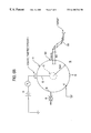
- FIG. 1 is a schematic illustration of an IEC device.
- FIG. 2 is a schematic illustration of an IEC-SS x-ray source in accordance with the present invention.
- FIG. 3 is a measured X-ray spectrum.
- FIG. 4 is an intensity vs wavelength graph pertinent to the present invention.
- FIG. 5 is an intensity vs wavelength graph pertinent to the present invention.
- FIG. 6 a is an illustration of a vacuum port target holder arrangement.
- FIG. 6 b is an illustration of an x-ray window-external target arrangement.
- FIG. 7 is a schematic illustration of a pin hole camera system for x-ray imaging using the x-ray source.
- the inertial electrostatic confinement device disclosed therein includes a vacuum vessel which is held at ground potential and contains internally and concentric to the vessel, a wire grid which acts as a cathode.
- the cathode may be made from a variety of metals having structural strength and appropriate secondary electron and thermionic electron coefficients.
- the cathode wire grid is connected to a power source to provide a high negative potential (30 kV-70 Kv), while the vessel itself is conductive and maintained at a ground potential.
- Deuterium or a mixture of deuterium and tritium gas is introduced into the vessel.
- a voltage is applied to the cathode wire grid and the pressure is adjusted in order initiate a glow discharge.
- operational conditions are used to create a “star” glow discharge mode.
- the glow discharge generates ions which are extracted from the discharge by the electric field created by the cathode grid. These ions are accelerated through the grid openings and focused at a spot in the center of the spherical device.
- the resulting high energy ions interact with the background gas (beam-background collisions) and themselves (beam-beam collisions) in a small volume around the center spot, resulting in a high rate of fusion reactions.
- the result is a neutron generator producing neutrons as one of the D-T fusion reaction products.
- the ejected ions may provide a deep-self generated potential well that confines trapped beam ions, creating even higher reaction rates.
- the device may be modified by using a field gas mixture of deuterium and helium-3 to be a source of protons as well as neutrons.
- One geometrical form of the device is spherical and as seen in FIG. 1 .
- This device is based upon the principle of an ion accelerator with a plasma target.
- deuterium-deuterium fusion reactions takes place in the plasma target and produce energetic neutrons.
- the device acts as a simple spherical plasma diode, having a ground potential on the outer sphere and a negative potential on a nearly geometrically transparent inner spherical grid.
- the spherical inertial electrostatic confinement device 10 is illustrated in FIG. 1 where a conductive vacuum chamber 11 is connected to a ground potential at contact 17 .
- the device has a cathode grid 12 which defines a small sphere within the chamber and has a grid design that provides a high geometric transparency.
- a source of power 14 is connected by a high voltage feed through to the internal cathode grid 12 .
- the voltage has a negative value, thereby providing a bias between the relatively positive walls of the vacuum chamber and the central grid area.
- Gas is introduced into the vacuum chamber 11 by a control valve 15 and is evacuated by a pump 18 .
- high density ions and electron beams Upon application of a potential to the cathode grid, under certain grid-voltage, gas pressure, gas type and grid-configuration conditions, high density ions and electron beams will form within the IEC device initiating a “star” mode of operation.
- high density space charged neutralized ion beams are formed into microchannels that pass through the open spaces between the grid wires. As the ions avoid contact with the wires, this mode increases the effective grid transparency to a level above the geometric value.
- These microchannels significantly reduce grid bombardment and erosion and increase power efficiency.
- the grid and microchannel beams are symmetric so that a convergent high-density core develops.
- the inertial electrostatic confinement device serves as a valuable source of neutrons or protons.
- the spherical inertial electrostatic confinement (IEC) device has been used as a plasma fusion reactor.
- the energy production must compete with inevitable losses, and the role of the processes which result in such losses is crucial in determining the operating temperature of a plasma fusion reactor.
- Some energy losses can be minimized by a suitable choice of certain design parameters, but others are inherent in the reacting system; one of these is bremsstrahlung radiation.
- the efficiency of neutron production competes with the inevitable losses of bremsstrahlung radiation that are inherent in the reacting system.
- High intensity x-rays were measured in experiments Hirsch's x-ray measurement. Previously, the goal was to minimize the bremsstrahlung radiation by a suitable choice of certain design parameters. Affirmative use of this property can permit a device to serve as x-ray source.
- An IEC plasma x-ray source may have the general structure as seen in FIG. 2, wherein electrons are injected into the center of a spherical IEC device 400 , formed from two spherical concentric electrodes.
- the inner electrode 401 (anode) made of a highly transparent grid (>90%, preferably >95%, transparency) is charged to a positive voltage, preferably in a range of 1 kV to 150 KV, relative to the outer grounded electrode 402 (cathode), at driving currents varying from 1 mA to 100 mA.
- the outer electrode is a hermedically sealed vacuum chamber that supports a pressure of less than 10 ⁇ 6 Torr.
- Electrons emanating from the cathode 402 are attracted to the anode 401 , and pass through the anode (grid) many times before being captured by the grid. Due to spherical convergence, the injection of electrons constitute an accumulation of electrons that forms a dense electron cloud which then can be used to accelerate and heat ions.
- the electrons are injected by electron emitters 409 which are electrically heated to generate the electrons.
- the operation generates intense bremsstrahlung radiation in the spherical center due to the strong electron—electron interactions at a relativistic speed accelerated by the grid bias.
- the energy spectrum of the emitted x-rays shifts as the grid bias is changed.
- the bias on this configuration is opposite to that seen in FIG. 1, wherein the central grid is a cathode and the chamber 11 serves as an anode.
- thermonuclear reactor consists of stripped nuclei of hydrogen isotopes together with electrons. From such a plasma, energy will inevitably be lost in the form of bremsstrahlung, that is, radiation emitted by charged particles, mainly the electrons, as a result of deflection by the Coulomb fields of other charged particles.
- T e is the kinetic temperature of the electrons in a Maxwellian distribution
- n e and n i are the density of electron and ion, respectively
- m e is the electron rest mass
- h Planck's constant.
- equation (2) Upon integration over all frequencies, this expression leads to equation (2).
- equation (3) expressed in terms of wave length, the relative values of Dp ⁇ ,/d ⁇ have been plotted as a function of wave length in FIG. 4 (From C. T. Ulrey: Phys. Rev., 11:401 (1918), as cited on page 616, Evans, The Atomic Nucleus , McGraw-Hill, Inc., (1972). While this calculation was performed for a thick tungsten target, the shape of the spectra is expected to be quite similar to that obtained from the IED due to the similarity of the x-ray production mechanisms.
- the energy emission as bremsstrahlung is dominated by the exponential term and decreases rapidly with decreasing wave length.
- the bremsstrahlung power distribution is calculated assuming a Maxwellian electron velocity distribution. For monoenergetic electron velocity, the distribution is expected to be narrower.
- the IEC spectrum in FIG. 3 was taken with the applied voltage set at 30 kV.
- the measured spectrum is somewhat broad having a 15 keV full-width at half-maximum (FWHM) for a spectrum ranging up to 230 kV (comparable to a 12 keV FWHM for E-30 keV in FIG. 4 ).
- the peak of the distribution can be shifted by varying the applied grid voltage to give a series of spectra similar to that of FIG. 4 .
- a broad-range spectrum of this nature is quite useful. However, in some cases it may be desirable to employ a narrow band of x-ray energies.
- a narrower spectrum or “band” can be selected by Bragg reflection from crystal surfaces, or by diffraction gratings, or by using other “conventional” x-ray optics techniques (J. B. Murphy et al., “Synchrotron radiation resources and condensers for projection x-ray lithography,” Appl. Optics, vol. 32, no. 34, pp. 6920-6929 (Dec. 1, 1933); I. A. Artyukov et al., “On the efficiency of grazing incidence optics: the spiral collimator,” in Short Wavelength Lasers and Their Applications , Nova Science Publishers, Inc., N.Y., pp. 299-310 (1992); H.
- the IEC voltage is first raised to 50 kV. This shifts the maximum intensity of the broad x-ray spectrum such that, as seen in the figure, the peak lies over the desired range. Then, an appropriate band selection technique (diffraction grating, etc.) is employed to select the 0.45-0.55 nm band. As observed from the figure, this procedure, adjusting the IEC x-ray spectrum followed by band selection, optimizes the x-ray intensity obtained in the desired range. If the IEC voltage had not been optimized, e.g., left at 30 kV or lower, the figure shows that the intensity in the desired band would be reduced by 50% or more.
- the tuned IEC x-ray can be used directly.
- Coupling of the band selection optics to the IEC x-ray source can be accomplished in a variety of ways. Two characteristic methods, illustrated in FIGS. 6 a and 6 b , differ by inserting the selection optics and target inside the IEC vacuum chamber 11 , or using external optics 501 with x-rays extracted from the vacuum vessel through a thin, vacuum-tight, metallic x-ray window 502 .
- FIG. 6 a uses “conventional” x-ray diffraction optics 451 (C. V. Azaroff, X-ray Spectroscopy McGraw-Hill, N.Y., (1973).) for band selection. It and the target 452 are located in an expanded port 453 on the side of the IEC.
- the port 453 is connected through an opening 404 in the main vacuum vessel such that x-rays escape the IEC grid region and enter the optics system while the port volume is maintained under vacuum conditions through the main chamber pumping system.
- a double valve 455 arrangement on the end of the port allows convenient insertion and removal of targets/specimens without breaking the main chamber vacuum. This method has the advantage that the x-rays escaping the IEC are not attenuated by use of a vacuum window (such as in FIG. 6 b ), and the target can be maintained under vacuum conditions.
- a vacuum window such as in FIG. 6 b
- FIG. 6 b If a slightly reduced x-ray intensity is tolerable, and if the target need not be maintained under vacuum, the external arrangement of FIG. 6 b can be used.
- x-rays from the IEC chamber 11 escape through a low-Z metallic window 502 .
- a low-Z material such as Be would be used to minimize x-ray attenuation which maintaining structural strength to hold vacuum conditions.
- Select glasses containing a minimum concentration of high-Z materials like lead could also be employed if visual observation into the chamber were desired.
- the two arrangements in FIG. 6 are considered typical examples. A number of variations in geometry, and selection optics, target/spectrum insertion/removal could be considered for specific applications. For example prisms also may be used.
- FIG. 7 A typical approach for adapting the IEC to this use is illustrated in FIG. 7 .
- the x-rays 600 are passed through a conventional pinhole camera system 604 , the image being recorded on a detector 605 as shown or on photographic film.
- the subject 603 being photographed would be placed in the x-ray path in the appropriate position desired to obtain the focal length.
- the subject would be sufficiently thin that x-ray transmission through it would be possible.
- An x-ray window is used in the arrangement illustrated in analogy with FIG. 6 b . However, if a vacuum arrangement is desired, a geometry similar to FIG. 6 a could be employed.
- the spherical wire grid 401 is a self-supporting structure, free from internal supports, having a plurality of openings through which electrons may flow.
- the grid also may be formed of a plurality of vanes, joined together in a geometric pattern which provides a thin profile when viewed in a radial direction in order to achieve a high geometric transparency. Due to the spherical convergence, the energetic electrons 403 collide in the center of sphere 404 . The interactions between the high energy electrons create intense x-rays. The x-ray spectra are dependent on the electron energy controlled by the grid bias 405 . The x-rays are directed to a window 406 in a wall of the vessel and transmitted via a cylindrical passage 407 to a detector 408 .
- a means for narrowing the spectrum of the x-rays could be disposed.
- Such means could be a device using Bragg reflection from a crystal surface, diffraction gratings, prisms, or the like.
- the IEC-SS makes possible the generation of x-rays using relatively low-energy electrons.
- the IEC-SS has a number of potentially unique and attractive features which may serve a variety of applications. These features include compactness, relatively low cost, tunability, high photon energy operation.
- the relatively narrow natural line-width associated with the IEC-SS can provide less unusable radiation which could damage optics and target samples.
- chirped x-ray pulses may be generated.
- the pulse structure, tunability and high photon energy capability of the IEC-SS may provide an important tool for studying ultra-fast phenomena.
- the relatively low cost and compactness of a IEC-SS can make synchrotron light sources more readily available to users.
- EXAFS Extended x-ray absorption fine structure
- SR synchrotron radiation
- e IEC-SS x-ray beam is to significantly enhance the imaging ability of low concentration of trace elements in the human body.
- DDA digital differential angiography
- This new technique is a differential x-ray absorption diagnostic procedure for imaging blood vessels.
- x-ray imaging of blood vessels is achieved by intravenously injecting an x-ray absorbing substance such as iodine.
- the available x-rays used for imaging are extremely broad band and large doses of both iodine and x-rays are required.
- a tunable x-ray beam, using a differential x-ray absorption technique, would be a very sensitive diagnostics tool for measuring low concentrations of iodine at a reduced radiation dose.
- Iodine has a K-edge absorption at a photon energy of ⁇ 33 kev.
- two x-ray beams are used: on at 33 kev (energy for peak absorption in iodine) and the other at ⁇ 30 kev.
- the mass attenuation coefficients for these two photon energies differ by a factor of ⁇ 8.
- the photon flush through the tissue is proportional to the exponent of the mass attenuation coefficient times the mass thickness of the tissue. Therefore, the difference between the 33 kev photon image and the 30 kev photon image is a direct and sensitive measure of the concentration of iodine, while the images of the bones and other tissues not containing the iodine is suppressed.
- This differential x-ray absorbing technique would use much lower concentrations of iodine injected “noninvasively” into the heart via the bloodstream. The imaging and subtraction of the two x-ray beams would be performed at the same time and, therefore, patient movement during the imaging process would not be a factor.
Abstract
A low cost small-scale tunable X-ray source, comprising a spherical-electron injected inertial electrostatic confinement (IEC) device. Within a spherical containment vessel (402) recirculatory focusing electrons are accelerated by a spherical grid (401) within the vessel, and cause electron-electron collisions in a dense, central plasma core region (404) of the sphere. The IEC synchrotron source (IEC-SS) in a mechanism for generating tunable X-ray radiation is essentially equivalent to that for conventional synchrotron sources. The IEC-SS operates at a much lower electron energy (<100 kev compared with >200 Mev in a synchrotron), but still gives the same X-ray energy due to the small-scale bending radius associated with the electron-electron interactions. The X-rays can be filtered for particular purposes using diffraction gratings, prisms or the like.
Description
This application claims domestic priority from U.S. Provisional Application Ser. No. 60/030,009 filed Nov. 1, 1996, and the entire e content of that application is incorporated herein by reference.
The development of a compact, tunable, hard x-ray source would have profound and wide ranging applications in a number of areas. These areas include x-ray diagnostics, medical imaging, microscopy, nuclear resonance absorption, solid-state physics and material science.
Currently, varieties of x-ray generators exist. The most modern devices are generally based on one of three methodologies: laser and discharge plasmas, electron impact sources, and synchrotron. The spectrum of these sources can be divided into two categories: characteristic x-rays and continuum x-rays. The characteristic x-ray sources are dependent on the particular atomic structure of the gas or target material in use. Among all the types of x-ray sources, only synchrotron produces continuum radiation.
The main interest in laser-generated plasma is directed towards inertial confined fusion. Recently, they have also gained interest as sources of (V)UV and x-rays. Laser-generated plasmas emit photons in an energy range, which can extend from visible light to hard x-rays. The observed emission spectrum is characteristic of a high-temperature, short-lived, high-density plasma. The sources produce a spectrum of x-rays centered about characteristic lines of the material.
In a laser-generated plasma x-ray source, when a high-power pulsed laser is focused on a (solid) target, a plasma is created. After the laser pulse terminates, the plasma cools extremely rapidly due to rapid thermal conduction, electron energy loss to ions, and expansion of the plasma into the surrounding vacuum. Cooling of the electrons at high density leads to fast recombination, quenching of the highly excited states, and a termination of the x-ray emission. The choice of target material controls the intrinsic range of the spectral output determined by the ionization states of the target material. Details of the spectral distribution are highly dependent on the target material (e.g., carbon, aluminum, titanium, copper, zinc, molybdenum, tin, tungsten, and lead) and other parameters (target thickness and source size).
Plasma discharge systems have been suggested as sources of high brightness x-ray radiation. Most of these devices (the gas puff J. Pearlman an J. C. Riordan, J. Vac. Sci. Technol. 19, 1190 (1981), plasma focus Y. Kato, et al, Appl. Phys. Lett. 48,686 (1986), and hypocycloidal pinch K. S. Han, et al, Bull. Am. Phys. 31, (1986)) are variations of the Z-pinch geometry. In Z-pinch devices, a high current is produced on the outer edge of a cylindrical volume of gas using a pulsed electrical driver such as a fast capacitor bank. The resulting JxB force accelerates the plasma shell radially inward to form a very high-temperature plasma on-axis which emits characteristic thermal radiation in the soft x-ray region.
The conventional electron impact sources use a suitable target material that is bombarded by a high-energy electron beam. These sources produce a broad spectrum of x-rays centered about characteristic lines of the material.
Synchrotron radiation is the electromagnetic radiation emitted by electrons moving at relativistic velocities along a curved trajectory with a large radius of curvature, for example, several meters to tens of meters. The energy of the photons ranges from a few electron volts to 105 Ev. This corresponds to the binding energy of electrons in atoms, molecules, solids, and biological systems. Thus, synchrotron radiation photons have the right energy to probe the properties of such electrons and of the corresponding chemical bonds to understand their physical and chemical properties. The uses of electron accelerators as sources of synchrotron radiation have grown enormously during the last two decades. Unique features such as tunability and wide x-ray spectrum tend to render the synchrotron irreplaceable for many applications.
Presently, third generation synchrotron sources are being pursued that are based on high-energy electron storage rings and bending magnets. A typical electron accelerator can be tuned to emit synchrotron radiation in a very broad range of photon energies, from microwaves to hard-x-rays. Thus, it provides electromagnetic radiation in spectral regions for which no other usable sources exist, e.g., most of the ultraviolet/soft-x-ray range. Furthermore, it is by far the best source of hard-x-rays, even though other sources exist for this range. The system has met most application needs, but fails with respect to physical size and cost. They are inevitably large and expensive devices requiring complex supporting facilities. The current machines are very large and costly with tens to hundreds of millions of dollars. The nature of synchrotron x-ray sources means that they are expensive, remote multi-user facilities, and are therefore not suited for use with a laboratory scale. The alternative x-ray sources, such as electron impact systems, laser and discharge plasmas, cannot match synchrotron in terms of its tunability and continuum x-rays.
An object of the invention disclosed is to provide a small compact tunable x-ray source.
Another object is to provide a compact tunable x-ray source for laboratory use. For applications where a relatively small sample is practical, the availability of a laboratory-scale source would be very advantageous.
Another object is to provide a compact tunable x-ray source for security inspection applications such as more sensitive balcale x-ray inspection systems.
A low cost, compact, tunable x-ray source, that is based on an inertial electrostatic confinement (IEC) vessel design, is proposed. The IEC device is described in pending U.S. patent application Ser. No. 08/232,764 for “Inertial-Electrostatic Confinement Particle Generator” and Ser. No. 08/491,127 for “Electrostatic Accelerated Recirculating Fusion Neutron/Proton Source” which are incorporated herein by reference.
In the IEC-based x-ray source design, the electron storage ring of the synchrotron is replaced by recirculatory focusing electrons in a sphere that are accelerated by a grid, and the bending magnets are replaced by the electron—electron collisions in the sphere center. This arrangement results in an IEC synchrotron source (IEC-SS), wherein the mechanism for generating tunable x-ray radiation is essentially the same as in the bending magnet synchrotron sources. The IEC-SS operates at a much lower electron energy (<100 keV compared with >200 MeV in a synchrotron) while still giving a same radiated x-ray energy compensated by a bending radius of much smaller scale from electron—electron interactions. In short, electrons are accelerated 10's to 100 kev by the anode grid. Due to spherical (or other) convergence, the energetic electrons scatter in the center of the sphere. The scattering interactions create intense bremsstrahlung x-rays. The emitted x-ray energy is controlled by the grid bias.
FIG. 1 is a schematic illustration of an IEC device.
FIG. 2 is a schematic illustration of an IEC-SS x-ray source in accordance with the present invention.
FIG. 3 is a measured X-ray spectrum.
FIG. 4 is an intensity vs wavelength graph pertinent to the present invention.
FIG. 5 is an intensity vs wavelength graph pertinent to the present invention.
FIG. 6a is an illustration of a vacuum port target holder arrangement.
FIG. 6b is an illustration of an x-ray window-external target arrangement.
FIG. 7 is a schematic illustration of a pin hole camera system for x-ray imaging using the x-ray source.
An inertial electrostatic confinement (IEC) particle generator is described in U.S. patent application Ser. No. 08/232,764 (Miley et al.) which was filed on Apr. 25, 1994 and is incorporated herein by reference. The inertial electrostatic confinement device disclosed therein includes a vacuum vessel which is held at ground potential and contains internally and concentric to the vessel, a wire grid which acts as a cathode. The cathode may be made from a variety of metals having structural strength and appropriate secondary electron and thermionic electron coefficients. The cathode wire grid is connected to a power source to provide a high negative potential (30 kV-70 Kv), while the vessel itself is conductive and maintained at a ground potential. Deuterium or a mixture of deuterium and tritium gas is introduced into the vessel. A voltage is applied to the cathode wire grid and the pressure is adjusted in order initiate a glow discharge. To maximize the neutron yield per unit power input while maximizing grid life-time by reducing collisions with a grid, operational conditions are used to create a “star” glow discharge mode. The glow discharge generates ions which are extracted from the discharge by the electric field created by the cathode grid. These ions are accelerated through the grid openings and focused at a spot in the center of the spherical device. The resulting high energy ions interact with the background gas (beam-background collisions) and themselves (beam-beam collisions) in a small volume around the center spot, resulting in a high rate of fusion reactions. The result is a neutron generator producing neutrons as one of the D-T fusion reaction products. Where the ejection rates are high, the ejected ions may provide a deep-self generated potential well that confines trapped beam ions, creating even higher reaction rates. The device may be modified by using a field gas mixture of deuterium and helium-3 to be a source of protons as well as neutrons. One geometrical form of the device is spherical and as seen in FIG. 1. This device is based upon the principle of an ion accelerator with a plasma target. In a neutron-generator embodiment, deuterium-deuterium fusion reactions takes place in the plasma target and produce energetic neutrons. The device acts as a simple spherical plasma diode, having a ground potential on the outer sphere and a negative potential on a nearly geometrically transparent inner spherical grid. The spherical inertial electrostatic confinement device 10 is illustrated in FIG. 1 where a conductive vacuum chamber 11 is connected to a ground potential at contact 17. The device has a cathode grid 12 which defines a small sphere within the chamber and has a grid design that provides a high geometric transparency. In operation, however, this grid design has an even higher effective transparency, due to the effect of a concentration of ions into a“microchannels”, as subsequently described. A source of power 14 is connected by a high voltage feed through to the internal cathode grid 12. The voltage has a negative value, thereby providing a bias between the relatively positive walls of the vacuum chamber and the central grid area. Gas is introduced into the vacuum chamber 11 by a control valve 15 and is evacuated by a pump 18.
Upon application of a potential to the cathode grid, under certain grid-voltage, gas pressure, gas type and grid-configuration conditions, high density ions and electron beams will form within the IEC device initiating a “star” mode of operation. In this mode, high density space charged neutralized ion beams are formed into microchannels that pass through the open spaces between the grid wires. As the ions avoid contact with the wires, this mode increases the effective grid transparency to a level above the geometric value. These microchannels significantly reduce grid bombardment and erosion and increase power efficiency. For conventional star mode operation, the grid and microchannel beams are symmetric so that a convergent high-density core develops. The inertial electrostatic confinement device serves as a valuable source of neutrons or protons.
The spherical inertial electrostatic confinement (IEC) device has been used as a plasma fusion reactor. In a plasma fusion reactor, the energy production must compete with inevitable losses, and the role of the processes which result in such losses is crucial in determining the operating temperature of a plasma fusion reactor. Some energy losses can be minimized by a suitable choice of certain design parameters, but others are inherent in the reacting system; one of these is bremsstrahlung radiation. The efficiency of neutron production competes with the inevitable losses of bremsstrahlung radiation that are inherent in the reacting system. High intensity x-rays were measured in experiments Hirsch's x-ray measurement. Previously, the goal was to minimize the bremsstrahlung radiation by a suitable choice of certain design parameters. Affirmative use of this property can permit a device to serve as x-ray source.
An IEC plasma x-ray source may have the general structure as seen in FIG. 2, wherein electrons are injected into the center of a spherical IEC device 400, formed from two spherical concentric electrodes. The inner electrode 401 (anode) made of a highly transparent grid (>90%, preferably >95%, transparency) is charged to a positive voltage, preferably in a range of 1 kV to 150 KV, relative to the outer grounded electrode 402 (cathode), at driving currents varying from 1 mA to 100 mA. The outer electrode is a hermedically sealed vacuum chamber that supports a pressure of less than 10−6 Torr. Electrons emanating from the cathode 402 are attracted to the anode 401, and pass through the anode (grid) many times before being captured by the grid. Due to spherical convergence, the injection of electrons constitute an accumulation of electrons that forms a dense electron cloud which then can be used to accelerate and heat ions. The electrons are injected by electron emitters 409 which are electrically heated to generate the electrons. There are at least two, preferably four to eight, such assemblies, and each assembly is comprised of an electron emitter and an electron extractor. The operation generates intense bremsstrahlung radiation in the spherical center due to the strong electron—electron interactions at a relativistic speed accelerated by the grid bias. The energy spectrum of the emitted x-rays shifts as the grid bias is changed. Notably, the bias on this configuration is opposite to that seen in FIG. 1, wherein the central grid is a cathode and the chamber 11 serves as an anode.
As is well known, the plasma in a thermonuclear reactor consists of stripped nuclei of hydrogen isotopes together with electrons. From such a plasma, energy will inevitably be lost in the form of bremsstrahlung, that is, radiation emitted by charged particles, mainly the electrons, as a result of deflection by the Coulomb fields of other charged particles.
An expression for the rate of electron-ion bremsstrahlung energy emission of the correct form L. Spitzer, USAEC Report NYO-6049 (1954), P. 9., but differing by a small numerical factor from the result obtained by a more rigorous procedure, can be derived from the classical expression for the rate Pe at which energy is radiated by an accelerated electron, namely, 
where e is the electron charge, c is the velocity of light, and a is the electron acceleration. The total power Pbr radiated as bremsstrahlung per unit volume has been calculated in a Maxwellian distribution of velocity among the electrons in a system containing a single ionic species of charge Z. S Glassston and R. H. Lovberg Controlled Thermonuclear Reactions, Van Nostrand Reinhold Company, 1960, Chapter 2. 
where Te is the kinetic temperature of the electrons in a Maxwellian distribution, ne and ni are the density of electron and ion, respectively, me is the electron rest mass, and h is Planck's constant. The classical expression for the rate of bremmstrahlung emission per unit volume per unit frequency interval in the frequency range from v to v+dv is 
Upon integration over all frequencies, this expression leads to equation (2). For arbitrary electron and ion densities, the equation (3) expressed in terms of wave length, the relative values of Dpλ,/dλ have been plotted as a function of wave length in FIG. 4 (From C. T. Ulrey: Phys. Rev., 11:401 (1918), as cited on page 616, Evans, The Atomic Nucleus, McGraw-Hill, Inc., (1972). While this calculation was performed for a thick tungsten target, the shape of the spectra is expected to be quite similar to that obtained from the IED due to the similarity of the x-ray production mechanisms. To the left of the maximum for each curve, the energy emission as bremsstrahlung is dominated by the exponential term and decreases rapidly with decreasing wave length. The bremsstrahlung power distribution is calculated assuming a Maxwellian electron velocity distribution. For monoenergetic electron velocity, the distribution is expected to be narrower.
At temperature below 50 kev, the bremsstrahlung from a plasma arises almost entirely from electron-ion interactions. At high temperatures, the production of bremsstrahlung due to electron—electron interactions, as distinct from those resulting from the electron-ion interactions, will be significant. Provided relativistic effects do not arise, there should be no electron—electron bremsttrahlung, but at high electron velocities such is not the case and appreciable losses can occur from this form of radiation. The following results will provide a general indication of the situation. At an electron kinetic temperature of 25 keV the ratio of electron—electron bremsstrahlung energy to that for electron-ion interaction is estimated to be 0.06, at 50 keV it is 0.13, and at 100 keV it is 0.34. C. F. Wandel, et al, Nuclear Instr., 4, 249 (1959). R. F. Post, Ann. Rev. Nuclear Sci, 9, 367 (1959).
In the IEC configuration, under proper conditions of current-voltage-pressure, a virtual cathode can form. [G. Miley et al, Inertial-Electrostatic Confinement Neutron/Proton Source, AIP conf. proc. 299. Editors: M. Haines, A. Knight.] In that case, deceleration of the electrons as they approach the virtual cathode makes an additional contribution to the x-ray yield. [R. Eisberg, Quantum Physics of Atoms, Molecules, Solids, Nuclei, and Particles, 2nd Ed., John Wiley and Sons, 1985.] This term can equal or dominate the electron/electron collisional contributions, depending of the height of the virtual cathode. Since electrons can lose their entire energy x-rays in this case, the effect generally causes a shift of the x-ray spectrum to higher energies.
Experimental measures of the x-ray spectrum have been carried out using the experiment setup described in FIG. 2. Results are shown in FIG. 3. As expected, the data follows along a curve very similar to calculated spectra, previously shown in FIG. 4.
The IEC spectrum in FIG. 3 was taken with the applied voltage set at 30 kV. The measured spectrum is somewhat broad having a 15 keV full-width at half-maximum (FWHM) for a spectrum ranging up to 230 kV (comparable to a 12 keV FWHM for E-30 keV in FIG. 4). The peak of the distribution can be shifted by varying the applied grid voltage to give a series of spectra similar to that of FIG. 4. For many experiments, a broad-range spectrum of this nature is quite useful. However, in some cases it may be desirable to employ a narrow band of x-ray energies.
If so, a narrower spectrum or “band” can be selected by Bragg reflection from crystal surfaces, or by diffraction gratings, or by using other “conventional” x-ray optics techniques (J. B. Murphy et al., “Synchrotron radiation resources and condensers for projection x-ray lithography,” Appl. Optics, vol. 32, no. 34, pp. 6920-6929 (Dec. 1, 1933); I. A. Artyukov et al., “On the efficiency of grazing incidence optics: the spiral collimator,” in Short Wavelength Lasers and Their Applications, Nova Science Publishers, Inc., N.Y., pp. 299-310 (1992); H. Takenaka et al., “Heat resistance of Mo-based and W-based multilayer soft x-ray mirrors,” in Laser Interaction and Rolation Plasma Phenomena, 12 International Conference, Osaka, Japan 1995, Part II, American Institute of Physics, pp. 808-813 (1992).) Such x-ray band selection is especially desirable in certain types of experiments or industrial applications where a narrow range of x-ray energies is desired. By using band selection techniques, the IEC voltage is first tuned to optimize the overall x-ray spectrum in the range desired. The x-ray band selector is then employed to further narrow the range of x-ray wavelengths striking the target or spectrum under treatment. This process is illustrated in FIG. 5. Assuming that x-rays in the wavelength range 0.45-0.55 nm are desired, the IEC voltage is first raised to 50 kV. This shifts the maximum intensity of the broad x-ray spectrum such that, as seen in the figure, the peak lies over the desired range. Then, an appropriate band selection technique (diffraction grating, etc.) is employed to select the 0.45-0.55 nm band. As observed from the figure, this procedure, adjusting the IEC x-ray spectrum followed by band selection, optimizes the x-ray intensity obtained in the desired range. If the IEC voltage had not been optimized, e.g., left at 30 kV or lower, the figure shows that the intensity in the desired band would be reduced by 50% or more.
Otherwise, if a narrow wavelength of x-rays is not required, the tuned IEC x-ray can be used directly.
Coupling of the band selection optics to the IEC x-ray source can be accomplished in a variety of ways. Two characteristic methods, illustrated in FIGS. 6a and 6 b, differ by inserting the selection optics and target inside the IEC vacuum chamber 11, or using external optics 501 with x-rays extracted from the vacuum vessel through a thin, vacuum-tight, metallic x-ray window 502. FIG. 6a uses “conventional” x-ray diffraction optics 451 (C. V. Azaroff, X-ray Spectroscopy McGraw-Hill, N.Y., (1973).) for band selection. It and the target 452 are located in an expanded port 453 on the side of the IEC. The port 453 is connected through an opening 404 in the main vacuum vessel such that x-rays escape the IEC grid region and enter the optics system while the port volume is maintained under vacuum conditions through the main chamber pumping system. A double valve 455 arrangement on the end of the port allows convenient insertion and removal of targets/specimens without breaking the main chamber vacuum. This method has the advantage that the x-rays escaping the IEC are not attenuated by use of a vacuum window (such as in FIG. 6b), and the target can be maintained under vacuum conditions. On the other hand, insertion and removal of the target/speculum through the double gate valve system is a complication. If a slightly reduced x-ray intensity is tolerable, and if the target need not be maintained under vacuum, the external arrangement of FIG. 6b can be used. Here x-rays from the IEC chamber 11 escape through a low-Z metallic window 502. A low-Z material such as Be would be used to minimize x-ray attenuation which maintaining structural strength to hold vacuum conditions. Select glasses containing a minimum concentration of high-Z materials like lead could also be employed if visual observation into the chamber were desired. The two arrangements in FIG. 6 are considered typical examples. A number of variations in geometry, and selection optics, target/spectrum insertion/removal could be considered for specific applications. For example prisms also may be used.
Other applications of the IEC x-ray source 601 involve x-ray imaging. Such techniques for using soft x-rays are well-known, e.g., I. H. Hutchinson, Principles of Plasma Diagnostics, Cambridge University Press, N.Y., (1987). A typical approach for adapting the IEC to this use is illustrated in FIG. 7. In this figure, the x-rays 600 are passed through a conventional pinhole camera system 604, the image being recorded on a detector 605 as shown or on photographic film. The subject 603 being photographed would be placed in the x-ray path in the appropriate position desired to obtain the focal length. The subject would be sufficiently thin that x-ray transmission through it would be possible. An x-ray window is used in the arrangement illustrated in analogy with FIG. 6b. However, if a vacuum arrangement is desired, a geometry similar to FIG. 6a could be employed.
The foregoing characteristics of the bremsstrahlung effect in a plasma can be the basis for the proper selection of parameters in an IEC device such that a turnable x-ray source can be achieved. As seen in FIG. 2, in an IEC-SS system 400 electrons from electron emitters 409, which are heated by application of an electric current of 1A to 15A at a driving voltage of 5-15V, from a source 410, are accelerated 10's keV up to 100 keV by a spherical anode grid 401 that is disposed within a spherical vacuum confinement vessel 402, which also serves as a cathode. The spherical wire grid 401 is a self-supporting structure, free from internal supports, having a plurality of openings through which electrons may flow. The grid also may be formed of a plurality of vanes, joined together in a geometric pattern which provides a thin profile when viewed in a radial direction in order to achieve a high geometric transparency. Due to the spherical convergence, the energetic electrons 403 collide in the center of sphere 404. The interactions between the high energy electrons create intense x-rays. The x-ray spectra are dependent on the electron energy controlled by the grid bias 405. The x-rays are directed to a window 406 in a wall of the vessel and transmitted via a cylindrical passage 407 to a detector 408. Within the passage or at other convenient locations in the path of the X-rays, a means for narrowing the spectrum of the x-rays could be disposed. Such means could be a device using Bragg reflection from a crystal surface, diffraction gratings, prisms, or the like. The IEC-SS makes possible the generation of x-rays using relatively low-energy electrons. The IEC-SS has a number of potentially unique and attractive features which may serve a variety of applications. These features include compactness, relatively low cost, tunability, high photon energy operation. The relatively narrow natural line-width associated with the IEC-SS can provide less unusable radiation which could damage optics and target samples. In addition, by varying the electron pulse energy in an IEC-SS pulsed mode, chirped x-ray pulses may be generated. The pulse structure, tunability and high photon energy capability of the IEC-SS may provide an important tool for studying ultra-fast phenomena. Furthermore, the relatively low cost and compactness of a IEC-SS can make synchrotron light sources more readily available to users.
Extended x-ray absorption fine structure (EXAFS), which is a powerful tool for structural determination in the materials, biomedical, and many other scientific fields, has been studied usually at synchrotron radiation (SR) facilities, so far. The development of instruments for EXAFS measurements in a laboratory is important because of their complementary usefulness for experiments with SR, especially when special sample preparation and/or quick feedback of the analysis are required. The problem with EXAFS measurements performed in a laboratory is mainly the degradation of spectrum caused by strong characteristic x-ray lines from the source. It is important to develop an x-ray source for dedicated use in EXAFS experiments. So far, the x-ray sources have been mostly used for x-ray diffractometry. Therefore, the electron gun is usually designed to operate at high tube voltage to provide strong characteristic x-rays. On the contrary, an EXAFS experiment requires intense continuum x-rays. The use of laboratory base IEC-SS may alleviate e this problem.
One practical application of the e IEC-SS x-ray beam is to significantly enhance the imaging ability of low concentration of trace elements in the human body. Specifically, it could be used in digital differential angiography (DDA), a new medical x-ray diagnostic concept. P. R. Moran, et al, Physics Today, July (1983); also in “Optics Today,” edited by J. N. Howard (AIP, New York, 1986), p. 308. This new technique is a differential x-ray absorption diagnostic procedure for imaging blood vessels. In conventional angiography, x-ray imaging of blood vessels is achieved by intravenously injecting an x-ray absorbing substance such as iodine. The available x-rays used for imaging are extremely broad band and large doses of both iodine and x-rays are required. A tunable x-ray beam, using a differential x-ray absorption technique, would be a very sensitive diagnostics tool for measuring low concentrations of iodine at a reduced radiation dose. Iodine has a K-edge absorption at a photon energy of ˜33 kev. In DDA, two x-ray beams are used: on at 33 kev (energy for peak absorption in iodine) and the other at ˜30 kev. The mass attenuation coefficients for these two photon energies differ by a factor of ˜8. The photon flush through the tissue is proportional to the exponent of the mass attenuation coefficient times the mass thickness of the tissue. Therefore, the difference between the 33 kev photon image and the 30 kev photon image is a direct and sensitive measure of the concentration of iodine, while the images of the bones and other tissues not containing the iodine is suppressed. This differential x-ray absorbing technique would use much lower concentrations of iodine injected “noninvasively” into the heart via the bloodstream. The imaging and subtraction of the two x-ray beams would be performed at the same time and, therefore, patient movement during the imaging process would not be a factor.
While the present invention has been described in connection with several preferred embodiments, the invention is not limited thereto, and its scope is to be defined by the following claims.
Claims (26)
1. A device for generating wave-length tunable x-rays comprising:
cathode means comprising a spherical vacuum vessel;
anode means comprising a highly transparent spherical grid defining a central spherical volume, said anode means being centrally disposed within said cathode means;
electron means comprising a plurality of electron emitter/extractor assemblies placed symmetrically near an internal surface of said cathode means for emitting electrons into said vessel;
means for creating a negative atmospheric pressure in said spherical vacuum vessel;
means for circulating electrons emitted by said electron emitter assemblies a plurality of times through a central region formed at the center of said spherical vacuum vessel;
means for focusing and converging high energy electrons in said central region;
means for applying an electric potential to said anode means whereby the potential between the anode and cathode means causes the electrons to accelerate towards the anode means, the increased energy electrons interacting with idle electrons in said central region thereby producing x-rays, whereby electrons at different energy levels produce x-rays at correspondingly different wave-lengths.
2. The device as set forth in claim 1 wherein said electron emitter/extractor assembly further comprises means for applying electric current to heat said electron emitter/extractor assemblies.
3. The device as set forth in claim 1 wherein said electron emitter/extractor assembly further comprises means for applying electric potential to said electron emitter/extractor assemblies to extract electrons.
4. The device as set forth in claim 1 wherein the spherical grid is a self-supporting structure, free from internal supports, having plurality of opening through which electrons may flow.
5. The device as set forth in claim 4 wherein said grid comprises at least one of a wire and a vane structure.
6. The device as set forth in claim 1 comprising at least 2 electron emitter assemblies.
7. The device as set forth in claim 6 comprising two to eight electron emitter assemblies.
8. The device as set forth in claim 1 wherein the electron emitter/extractor assembly comprises an electron emitter and an electron extractor.
9. The device as set forth in claim 2 wherein said cathode means is held at ground potential and the anode means is a conductive electrode having power leads connected, passing through the spherical vacuum vessel and insulated therefrom and being connected to the means for applying electric potential.
10. The device as set forth in claim 1 wherein said spherical vacuum vessel is hermetically sealed metallic shell.
11. The device as set forth in claim 1 wherein the means for applying electric potential to said anode grid provides a positive potential within a range between 1 Kv to 150 Kv.
12. The device as set forth in claim 1 wherein the means for applying electric potential to anode grid employs driving currents within a range of 1 Ma to 100 Ma.
13. The device as set forth in claim 1 wherein said grid has a geometric transparency of greater than or equal to 95%.
14. The device as set forth in claim 1 wherein the pressure in said spherical vacuum vessel is less than 10−6 Torr.
15. The device as set forth in claim 1 wherein said electric potential to the anode means is within a range of positive potential between 50 V to 300 V.
16. The device of claim 3 wherein said means for applying an electric potential to said electron extractor employs driving currents varying in a range between 10 Ma to 5 A.
17. The device in claim 2 wherein the means for applying electric current to heat said electron emitter provides a current that varies within a range between 1 A to 15 A inclusive.
18. The device in claim 3 wherein the means for applying electric current to heat said electron emitter employs a driving voltage that varies within a range varying from 5 V to 15 V inclusive.
19. The device in claim 1 wherein said grid comprises at least one of a wire and a vane structure, whereby the profile when viewed in any radial direction will be thin and thus achieve high geometric transparency defining a central spherical volume.
20. The device in claim 1 further comprising means for narrowing the spectrum of said produced x-rays.
21. The device of claim 20 wherein said means utilizes at least one of defraction gratings or prisms.
22. The device of claim 1 further comprising means for having a target for said x-rays disposed within said vacuum vessel.
23. The device of claim 1 further comprising a window for permitting x-rays to escape from said vacuum vessel.
24. The device of claim 23 further comprising means for having a target for said x-rays disposed outside of said vacuum vessel.
25. The device of claim 24 further comprising a camera system for receiving x-rays passing through said target.
26. The device of claim 22 further comprising a camera system for receiving x-rays passing through said target.
Priority Applications (1)
| Application Number | Priority Date | Filing Date | Title |
|---|---|---|---|
| US09/297,506 US6188746B1 (en) | 1996-11-01 | 1997-10-31 | Spherical inertial electrostatic confinement device as a tunable x-ray source |
Applications Claiming Priority (3)
| Application Number | Priority Date | Filing Date | Title |
|---|---|---|---|
| US3000996P | 1996-11-01 | 1996-11-01 | |
| US09/297,506 US6188746B1 (en) | 1996-11-01 | 1997-10-31 | Spherical inertial electrostatic confinement device as a tunable x-ray source |
| PCT/US1997/019307 WO1998020499A1 (en) | 1996-11-01 | 1997-10-31 | Spherical inertial electrostatic confinement device as a tunable x-ray source |
Publications (1)
| Publication Number | Publication Date |
|---|---|
| US6188746B1 true US6188746B1 (en) | 2001-02-13 |
Family
ID=21852053
Family Applications (1)
| Application Number | Title | Priority Date | Filing Date |
|---|---|---|---|
| US09/297,506 Expired - Fee Related US6188746B1 (en) | 1996-11-01 | 1997-10-31 | Spherical inertial electrostatic confinement device as a tunable x-ray source |
Country Status (9)
| Country | Link |
|---|---|
| US (1) | US6188746B1 (en) |
| EP (1) | EP1010184A4 (en) |
| JP (1) | JP2001503866A (en) |
| KR (1) | KR20000052855A (en) |
| CN (1) | CN1237264A (en) |
| AU (1) | AU7003598A (en) |
| CA (1) | CA2268465A1 (en) |
| IL (1) | IL129609A0 (en) |
| WO (1) | WO1998020499A1 (en) |
Cited By (13)
| Publication number | Priority date | Publication date | Assignee | Title |
|---|---|---|---|---|
| US6421421B1 (en) * | 2000-05-22 | 2002-07-16 | Plex, Llc | Extreme ultraviolet based on colliding neutral beams |
| US20020186815A1 (en) * | 2001-06-07 | 2002-12-12 | Plex Llc | Star pinch plasma source of photons or neutrons |
| US6567499B2 (en) | 2001-06-07 | 2003-05-20 | Plex Llc | Star pinch X-ray and extreme ultraviolet photon source |
| WO2003085418A2 (en) * | 2002-04-05 | 2003-10-16 | Bundesrepublik Deutschland, vertreten durch das Bundesministerium für Wirtschaft und Arbeit, dieses vertreten durch den Präsidenten der Physikalisch-Technischen Bundesanstalt | Chemical analysis of test objects using neutrons that are generated by concentrically accelerated deuterium ions |
| US6658088B2 (en) * | 2000-11-09 | 2003-12-02 | Radi Medical Technologies Ab | Miniature X-ray source and method |
| US6724782B2 (en) | 2002-04-30 | 2004-04-20 | The Regents Of The University Of California | Femtosecond laser-electron x-ray source |
| US6922455B2 (en) * | 2002-01-28 | 2005-07-26 | Starfire Industries Management, Inc. | Gas-target neutron generation and applications |
| US20060067476A1 (en) * | 2004-07-27 | 2006-03-30 | Jmar Research, Inc. | Rotating shutter for laser-produced plasma debris mitigation |
| US20080063132A1 (en) * | 2006-05-30 | 2008-03-13 | Birnbach Curtis A | Method and system for controlled fusion reactions |
| US20080226010A1 (en) * | 2005-10-24 | 2008-09-18 | Steven Arnold Sesselmann | Reactor For Producing Controlled Nuclear Fusion |
| AU2013201537B2 (en) * | 2006-05-30 | 2015-05-21 | Advanced Fusion Systems Llc | Electron-coupled transformer |
| US20180049305A1 (en) * | 2015-04-16 | 2018-02-15 | Halliburton Energy Services, Inc. | Field-ionization neutron generator |
| WO2021158323A1 (en) * | 2020-02-05 | 2021-08-12 | Canazon John | X-ray tube with distributed filaments |
Families Citing this family (8)
| Publication number | Priority date | Publication date | Assignee | Title |
|---|---|---|---|---|
| CA2477960C (en) * | 2002-08-14 | 2010-08-03 | Ltd Company "Proton-21" | Method and device for compressing a substance by impact and plasma cathode thereto |
| KR101013144B1 (en) * | 2009-03-20 | 2011-02-10 | 서울대학교산학협력단 | An inertial electrostatic confinement fusion device with an electron source |
| US8837661B2 (en) * | 2009-07-24 | 2014-09-16 | The Regents Of The University Of California | Radionuclide production using a Z-pinch neutron source |
| WO2011014801A2 (en) * | 2009-07-30 | 2011-02-03 | The Regents Of The University Of California | Staged z-pinch for the production of high-flux neutrons and net energy |
| WO2012007456A1 (en) * | 2010-07-12 | 2012-01-19 | Ge Healthcare As | X-ray imaging at low contrast agent concentrations and/or low dose radiation |
| KR101139878B1 (en) * | 2010-09-10 | 2012-05-02 | 포항공과대학교 산학협력단 | Device of acqusiting x-ray image for particle image velocimetry and acquisition method of x-ray image for the same |
| WO2013104690A1 (en) * | 2012-01-11 | 2013-07-18 | Ge Healthcare As | X-ray imaging contrast media with low iodine concentration and x-ray imaging process |
| CN111140447A (en) * | 2019-12-23 | 2020-05-12 | 北京航空航天大学 | Vector magnetic nozzle for electric propulsion comprising a bypass electromagnetic coil |
Citations (3)
| Publication number | Priority date | Publication date | Assignee | Title |
|---|---|---|---|---|
| US4955045A (en) | 1988-04-08 | 1990-09-04 | Siemens Aktiengesellschaft | Plasma X-ray tube, in particular for X-ray preionization of gas lasers and method for produicng X-radiation with such an X-ray tube |
| US5323422A (en) | 1991-11-29 | 1994-06-21 | Nec Corporation | Adaptive receiver apparatus |
| US5504795A (en) * | 1995-02-06 | 1996-04-02 | Plex Corporation | Plasma X-ray source |
Family Cites Families (2)
| Publication number | Priority date | Publication date | Assignee | Title |
|---|---|---|---|---|
| US3822382A (en) * | 1971-08-17 | 1974-07-02 | Jeol Ltd | Apparatus for analyzing electron energy |
| US5323442A (en) * | 1992-02-28 | 1994-06-21 | Ruxam, Inc. | Microwave X-ray source and methods of use |
-
1997
- 1997-10-31 KR KR1019990703689A patent/KR20000052855A/en not_active Application Discontinuation
- 1997-10-31 CA CA002268465A patent/CA2268465A1/en not_active Abandoned
- 1997-10-31 CN CN97199315A patent/CN1237264A/en active Pending
- 1997-10-31 IL IL12960997A patent/IL129609A0/en unknown
- 1997-10-31 EP EP97949338A patent/EP1010184A4/en not_active Withdrawn
- 1997-10-31 JP JP52148598A patent/JP2001503866A/en active Pending
- 1997-10-31 AU AU70035/98A patent/AU7003598A/en not_active Abandoned
- 1997-10-31 US US09/297,506 patent/US6188746B1/en not_active Expired - Fee Related
- 1997-10-31 WO PCT/US1997/019307 patent/WO1998020499A1/en not_active Application Discontinuation
Patent Citations (3)
| Publication number | Priority date | Publication date | Assignee | Title |
|---|---|---|---|---|
| US4955045A (en) | 1988-04-08 | 1990-09-04 | Siemens Aktiengesellschaft | Plasma X-ray tube, in particular for X-ray preionization of gas lasers and method for produicng X-radiation with such an X-ray tube |
| US5323422A (en) | 1991-11-29 | 1994-06-21 | Nec Corporation | Adaptive receiver apparatus |
| US5504795A (en) * | 1995-02-06 | 1996-04-02 | Plex Corporation | Plasma X-ray source |
Cited By (22)
| Publication number | Priority date | Publication date | Assignee | Title |
|---|---|---|---|---|
| US6421421B1 (en) * | 2000-05-22 | 2002-07-16 | Plex, Llc | Extreme ultraviolet based on colliding neutral beams |
| US6658088B2 (en) * | 2000-11-09 | 2003-12-02 | Radi Medical Technologies Ab | Miniature X-ray source and method |
| US20020186815A1 (en) * | 2001-06-07 | 2002-12-12 | Plex Llc | Star pinch plasma source of photons or neutrons |
| US6567499B2 (en) | 2001-06-07 | 2003-05-20 | Plex Llc | Star pinch X-ray and extreme ultraviolet photon source |
| US6728337B2 (en) | 2001-06-07 | 2004-04-27 | Plex Llc | Star pinch plasma source of photons or neutrons |
| US6922455B2 (en) * | 2002-01-28 | 2005-07-26 | Starfire Industries Management, Inc. | Gas-target neutron generation and applications |
| WO2003085418A2 (en) * | 2002-04-05 | 2003-10-16 | Bundesrepublik Deutschland, vertreten durch das Bundesministerium für Wirtschaft und Arbeit, dieses vertreten durch den Präsidenten der Physikalisch-Technischen Bundesanstalt | Chemical analysis of test objects using neutrons that are generated by concentrically accelerated deuterium ions |
| WO2003085418A3 (en) * | 2002-04-05 | 2003-12-18 | Bundesrep Deutschland | Chemical analysis of test objects using neutrons that are generated by concentrically accelerated deuterium ions |
| US20050195932A1 (en) * | 2002-04-05 | 2005-09-08 | Uwe Keyser | Method and device for promptly conducting non-destructive chemical analysis of test objects |
| US6724782B2 (en) | 2002-04-30 | 2004-04-20 | The Regents Of The University Of California | Femtosecond laser-electron x-ray source |
| US20060067476A1 (en) * | 2004-07-27 | 2006-03-30 | Jmar Research, Inc. | Rotating shutter for laser-produced plasma debris mitigation |
| US7302043B2 (en) | 2004-07-27 | 2007-11-27 | Gatan, Inc. | Rotating shutter for laser-produced plasma debris mitigation |
| US20080226010A1 (en) * | 2005-10-24 | 2008-09-18 | Steven Arnold Sesselmann | Reactor For Producing Controlled Nuclear Fusion |
| US20080063132A1 (en) * | 2006-05-30 | 2008-03-13 | Birnbach Curtis A | Method and system for controlled fusion reactions |
| WO2008033587A3 (en) * | 2006-05-30 | 2008-06-26 | Curtis A Birnbach | Method and system for controlled fusion reactions |
| US9036765B2 (en) | 2006-05-30 | 2015-05-19 | Advanced Fusion Systems Llc | Method and system for inertial confinement fusion reactions |
| AU2013201537B2 (en) * | 2006-05-30 | 2015-05-21 | Advanced Fusion Systems Llc | Electron-coupled transformer |
| US10181376B2 (en) | 2006-05-30 | 2019-01-15 | Advanced Fusion Systems Llc | Electron-coupled transformer |
| US20180049305A1 (en) * | 2015-04-16 | 2018-02-15 | Halliburton Energy Services, Inc. | Field-ionization neutron generator |
| US10455684B2 (en) * | 2015-04-16 | 2019-10-22 | Halliburton Energy Services, Inc. | Field-ionization neutron generator |
| WO2021158323A1 (en) * | 2020-02-05 | 2021-08-12 | Canazon John | X-ray tube with distributed filaments |
| US11404235B2 (en) | 2020-02-05 | 2022-08-02 | John Thomas Canazon | X-ray tube with distributed filaments |
Also Published As
| Publication number | Publication date |
|---|---|
| WO1998020499A1 (en) | 1998-05-14 |
| EP1010184A1 (en) | 2000-06-21 |
| KR20000052855A (en) | 2000-08-25 |
| IL129609A0 (en) | 2000-02-29 |
| EP1010184A4 (en) | 2001-07-25 |
| JP2001503866A (en) | 2001-03-21 |
| CN1237264A (en) | 1999-12-01 |
| CA2268465A1 (en) | 1998-05-14 |
| AU7003598A (en) | 1998-05-29 |
Similar Documents
| Publication | Publication Date | Title |
|---|---|---|
| US6188746B1 (en) | Spherical inertial electrostatic confinement device as a tunable x-ray source | |
| Downer et al. | Diagnostics for plasma-based electron accelerators | |
| Rullhusen et al. | Novel radiation sources using relativistic electrons: from infrared to x-rays | |
| Kneip et al. | Observation of synchrotron radiation from electrons accelerated in a petawatt-laser-generated plasma cavity | |
| Zepf et al. | Fast particle generation and energy transport in laser-solid interactions | |
| US5680018A (en) | Method and apparatus for generating radiation | |
| WO1998057335A1 (en) | Thin radiators in a recycled electron beam | |
| Fortov et al. | Intense ion beams for generating extreme states of matter | |
| Bacal et al. | Negative ion sources | |
| US4867939A (en) | Process for preparing antihydrogen | |
| Láska et al. | Iodine laser production of highly charged Ta ions | |
| Venable et al. | PHERMEX: A PULSED HIGH-ENERGY RADIOGRAPHIC MACHINE EMITTING X-RAYS. | |
| Alexander et al. | Short pulse laser-induced dissociation of vibrationally cold, trapped molecular ions | |
| Szydlowski | Application of CR-39 track detectors for corpuscular diagnostics of high-temperature plasmas | |
| Zakaullah et al. | Correlation of plasma electron temperature with neutron emission in a low-energy plasma focus | |
| Gaudin et al. | X-ray emission from a compact hot plasma: applications to radiology and mammography | |
| MXPA99003910A (en) | Spherical inertial electrostatic confinement device as a tunable x-ray source | |
| Danisch | Search for the O4+ 16/O4+ 18 isotope shift in the photoionization of Be-like oxygen with monochromatic soft X-ray synchrotron radiation. | |
| Bruni et al. | ThomX: A high flux compact X ray source | |
| Ledingham | A vision for laser induced particle acceleration and applications | |
| Gammino | Proton and heavy ion acceleration driven by high intensity-short pulse lasers | |
| Childers | Application of X-ray Line Polarization to High-Energy-Density X-pinch Ne-like Mo Plasmas | |
| Khan et al. | Accelerator-Based Photon Sources | |
| Desforges et al. | Analysis of electron injection in laser wakefield acceleration using betatron emission in capillary tubes | |
| Kapitza et al. | Trends in electron accelerator applications |
Legal Events
| Date | Code | Title | Description |
|---|---|---|---|
| AS | Assignment |
Owner name: BOARD OF TRUSTEES OF UNIVERSITY OF ILLINOIS, THE, Free format text: ASSIGNMENT OF ASSIGNORS INTEREST;ASSIGNORS:MILEY, GEORGE H.;GU, YIBIN;REEL/FRAME:010869/0649;SIGNING DATES FROM 20000417 TO 20000420 |
|
| REMI | Maintenance fee reminder mailed | ||
| LAPS | Lapse for failure to pay maintenance fees | ||
| STCH | Information on status: patent discontinuation |
Free format text: PATENT EXPIRED DUE TO NONPAYMENT OF MAINTENANCE FEES UNDER 37 CFR 1.362 |
|
| FP | Lapsed due to failure to pay maintenance fee |
Effective date: 20050213 |