US6173467B1 - Multifunctional tool - Google Patents
Multifunctional tool Download PDFInfo
- Publication number
- US6173467B1 US6173467B1 US09/348,109 US34810999A US6173467B1 US 6173467 B1 US6173467 B1 US 6173467B1 US 34810999 A US34810999 A US 34810999A US 6173467 B1 US6173467 B1 US 6173467B1
- Authority
- US
- United States
- Prior art keywords
- hose
- main body
- multifunctional tool
- rigid tube
- telescopic member
- Prior art date
- Legal status (The legal status is an assumption and is not a legal conclusion. Google has not performed a legal analysis and makes no representation as to the accuracy of the status listed.)
- Expired - Fee Related
Links
Images


Classifications
-
- B—PERFORMING OPERATIONS; TRANSPORTING
- B25—HAND TOOLS; PORTABLE POWER-DRIVEN TOOLS; MANIPULATORS
- B25B—TOOLS OR BENCH DEVICES NOT OTHERWISE PROVIDED FOR, FOR FASTENING, CONNECTING, DISENGAGING OR HOLDING
- B25B11/00—Work holders not covered by any preceding group in the subclass, e.g. magnetic work holders, vacuum work holders
- B25B11/002—Magnetic work holders
-
- B—PERFORMING OPERATIONS; TRANSPORTING
- B25—HAND TOOLS; PORTABLE POWER-DRIVEN TOOLS; MANIPULATORS
- B25B—TOOLS OR BENCH DEVICES NOT OTHERWISE PROVIDED FOR, FOR FASTENING, CONNECTING, DISENGAGING OR HOLDING
- B25B15/00—Screwdrivers
- B25B15/02—Screwdrivers operated by rotating the handle
-
- B—PERFORMING OPERATIONS; TRANSPORTING
- B25—HAND TOOLS; PORTABLE POWER-DRIVEN TOOLS; MANIPULATORS
- B25B—TOOLS OR BENCH DEVICES NOT OTHERWISE PROVIDED FOR, FOR FASTENING, CONNECTING, DISENGAGING OR HOLDING
- B25B9/00—Hand-held gripping tools other than those covered by group B25B7/00
-
- B—PERFORMING OPERATIONS; TRANSPORTING
- B25—HAND TOOLS; PORTABLE POWER-DRIVEN TOOLS; MANIPULATORS
- B25G—HANDLES FOR HAND IMPLEMENTS
- B25G1/00—Handle constructions
- B25G1/02—Handle constructions flexible
- B25G1/025—Handle constructions flexible for screwdrivers, wrenches or spanners
-
- B—PERFORMING OPERATIONS; TRANSPORTING
- B25—HAND TOOLS; PORTABLE POWER-DRIVEN TOOLS; MANIPULATORS
- B25G—HANDLES FOR HAND IMPLEMENTS
- B25G1/00—Handle constructions
- B25G1/04—Handle constructions telescopic; extensible; sectional
- B25G1/043—Handle constructions telescopic; extensible; sectional for screwdrivers, wrenches or spanners
-
- B—PERFORMING OPERATIONS; TRANSPORTING
- B25—HAND TOOLS; PORTABLE POWER-DRIVEN TOOLS; MANIPULATORS
- B25G—HANDLES FOR HAND IMPLEMENTS
- B25G1/00—Handle constructions
- B25G1/08—Handle constructions with provision for storing tool elements
- B25G1/085—Handle constructions with provision for storing tool elements for screwdrivers, wrenches or spanners
-
- Y—GENERAL TAGGING OF NEW TECHNOLOGICAL DEVELOPMENTS; GENERAL TAGGING OF CROSS-SECTIONAL TECHNOLOGIES SPANNING OVER SEVERAL SECTIONS OF THE IPC; TECHNICAL SUBJECTS COVERED BY FORMER USPC CROSS-REFERENCE ART COLLECTIONS [XRACs] AND DIGESTS
- Y10—TECHNICAL SUBJECTS COVERED BY FORMER USPC
- Y10S—TECHNICAL SUBJECTS COVERED BY FORMER USPC CROSS-REFERENCE ART COLLECTIONS [XRACs] AND DIGESTS
- Y10S7/00—Compound tools
- Y10S7/901—Magnetic feature
Definitions
- the present invention relates to a multifunctional tool that includes a telescopic hose with a magnetic member at a distal end thereof for removing a fastener from a place difficult to access.
- the telescopic hose can be completely retracted into a main body of the multifunctional tool, and a bit can be attached to the main body to function as a driving tool.
- U.S. Pat. No. 5,878,637 to Liu issued on Mar. 9, 1999 discloses a driving tool that includes a barrel, a handle secured to a first end of the barrel for rotating the barrel, and a telescopic pipe engaged in a bore of the barrel and having a first end secured to the handle and a second end extended outward of the bore of the barrel.
- a magnetic member is secured to the second end of the telescopic pipe, thereby allowing the magnetic member to be extended outward of the bore of the barrel for removing fasteners dropped in a deep hole after unfastening of the fasteners.
- function of the driving tool is limited, as the barrel cannot be detached from the handle for operation purpose.
- the present invention is intended to provide a multifunctional tool that mitigates and/or obviates the above problems.
- the telescopic hose can be completely retracted into a main body of the multifunctional tool, and a bit can be attached to the main body to function as a driving tool.
- a bit carrier is mounted to the main body and is pivotable between a storage position inside the main body and an exposed position such that the user may select the required bit among a plurality of bits carried by the bit carrier.
- FIG. 1 is a perspective view of a multifunctional tool in accordance with the present invention
- FIG. 2 is an exploded perspective view of the multifunctional tool in accordance with the present invention.
- FIG. 3 is a top view of the multifunctional tool in accordance with the present invention, illustrating insertion of a bit
- FIG. 4 is a top view similar to FIG. 3, wherein a hose arrangement is extended outward of a rigid tube of the main body;
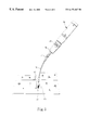
- FIG. 5 is a schematic view illustrating use of the hose arrangement of the multifunctional tool, wherein the rigid tool has been removed.
- FIG. 6 is a top view of the multifunctional tool, wherein a bit carrier is pivoted to an exposed position.
- a multifunctional tool in accordance with the present invention generally includes a main body 10 that includes a first compartment 12 for receiving a bit carrier 22 and a second compartment 14 for receiving a battery unit (not shown).
- the main body 10 further includes a connecting end 16 with a socket 18 .
- a rigid tube 32 includes a hexagonal engaging end 38 that is securely yet removably received in the socket 18 of the connecting end 16 of the main body 10 .
- a first telescopic hose 34 is telescopically received in the rigid tube 32 .
- the first telescopic hose 34 is extendible out of the rigid tube 32 until a rear end (not labeled) of the hose 34 is stopped by an end opening 33 of the rigid tube 32 that has a diameter smaller than that of the rear end of the hose 34 .
- a second telescopic hose 36 is telescopically received in the first telescopic hose 34 .
- the second telescopic hose 36 is extendible out of the first telescopic hose 34 until a rear end (not labeled) of the hose 36 is stopped by an end opening 35 of the rigid tube 32 that has a diameter smaller than that of the rear end (not labeled) of the hose 36 .
- a magnetic member 37 is attached to a distal end of the second telescopic hose 36 .
- the first telescopic hose 34 may be collapsed so as to be completely received in the rigid tube 32
- the second telescopic hose 36 may be collapsed so as to be completely received in the first telescopic hose 34 .
- Each of the first and second telescopic hoses 34 and 36 may include a number of hose sections thereby allowing further collapse.
- Two end walls 13 defining the first compartment 12 include aligned groove tracks.
- An upper lid 20 includes a block 28 on each of two ends thereof so as to be slidable along an associated groove track of end walls 13 .
- Two guide pins 15 are extended through the upper lid 20 and two screws 19 are extended through holes 19 a in the main body 10 to securely engage with threaded holes (not shown) in the guide pins 15 .
- a spring 17 is mounted around each guide pin 15 and attached between the upper lid 20 and the main body 10 .
- Wire stripping devices 27 and 29 are provided on the main body 10 and the upper lid 20 such that the wire stripping devices 27 and 29 may perform a wire stripping function when the upper lid 20 is manually pressed.
- Such arrangement has been disclosed in Applicant's U.S. Pat. No. 08/977,631 filed on Nov. 25, 1997, now U.S. Pat. No. 5,956,789, which is incorporated herein for reference.
- a bit carrier 22 has an end pivotally connected to the main body 10 by means of extending a pin 26 through a pin hole 11 in the main body 10 and a pin hole 23 in the bit carrier 22 .
- the bit carrier 22 carries a number of bits 24
- a retaining projection 25 is formed on the other end of the bit carrier 22 for releasable engagement with a depression 25 a (FIG. 6) defined in the main body 10 .
- a circuit board 42 having number of lamps 44 (e.g., light emitting diodes) thereon is mounted in the main body.
- the lamps 44 are located in lamp holes 40 in the main body 10 .
- a switch 30 is provided to turn on/off the lamps 44 .
- the first and second telescopic hoses 34 and 36 are completely collapsed and thus hidden inside the rigid tube 32 .
- the user may attach a bit 24 to the end opening 33 of the rigid tube 32 and thus function as a driving tool.
- the bit carrier 22 may be pivoted to the exposed position when required, thereby allowing the user to find the proper bit 24 in an easier way.
- the fastener e.g., a screw 50 , see FIG. 5
- the first and second telescopic hoses 34 and 36 are extended (FIG. 4) to remove the screw 50 .
- the rigid tube 32 is detached from the main body 10 , as shown in FIG. 5 .
- the first and second telescopic hoses 34 and 36 are extended outward to remove the screw 50 by means of magnetic attraction provided by the magnetic member 37 .
- Such action can be easily achieved, as the first and second telescopic hoses 34 and 36 are flexible.
- the first and second telescopic hoses 34 and 36 can be collapsed and can be hidden inside the main body 10 . It is appreciated that the main body 10 securely holds the rear end of the first telescopic hose 34 if the rigid tube 32 is removed.
- the multifunctional tool in accordance with the present invention is more versatile, as the rigid tube 32 can be removed without affecting the screw removing function.
- the bit carrier 22 allows easy and rapid replacement and/or selection of the bits 24 .
- lamps 44 are provided to illuminate when necessary.
Landscapes
- Engineering & Computer Science (AREA)
- Mechanical Engineering (AREA)
- Workshop Equipment, Work Benches, Supports, Or Storage Means (AREA)
- Knives (AREA)
Priority Applications (2)
| Application Number | Priority Date | Filing Date | Title |
|---|---|---|---|
| US09/348,109 US6173467B1 (en) | 1999-07-06 | 1999-07-06 | Multifunctional tool |
| DE19935175A DE19935175A1 (de) | 1999-07-06 | 1999-07-28 | Multifunktionswerkzeug |
Applications Claiming Priority (2)
| Application Number | Priority Date | Filing Date | Title |
|---|---|---|---|
| US09/348,109 US6173467B1 (en) | 1999-07-06 | 1999-07-06 | Multifunctional tool |
| DE19935175A DE19935175A1 (de) | 1999-07-06 | 1999-07-28 | Multifunktionswerkzeug |
Publications (1)
| Publication Number | Publication Date |
|---|---|
| US6173467B1 true US6173467B1 (en) | 2001-01-16 |
Family
ID=26054354
Family Applications (1)
| Application Number | Title | Priority Date | Filing Date |
|---|---|---|---|
| US09/348,109 Expired - Fee Related US6173467B1 (en) | 1999-07-06 | 1999-07-06 | Multifunctional tool |
Country Status (2)
| Country | Link |
|---|---|
| US (1) | US6173467B1 (de) |
| DE (1) | DE19935175A1 (de) |
Cited By (9)
| Publication number | Priority date | Publication date | Assignee | Title |
|---|---|---|---|---|
| US6684740B2 (en) * | 2002-04-26 | 2004-02-03 | Ching Chou Lin | Magnetic device for retaining tool members to drivers |
| US20050247170A1 (en) * | 2004-05-07 | 2005-11-10 | Nieh Chuang Industrial Co., Ltd. | Tool handle self-contained a set of screwdriver bits |
| US20050279194A1 (en) * | 2004-06-16 | 2005-12-22 | Nieh Chuang Industrial Co., Ltd. | Tool handle self-contained a set of head tips |
| US7039975B1 (en) * | 2005-06-01 | 2006-05-09 | Youn Chyuan Liao | Tool having detachable handle members |
| CN100360281C (zh) * | 2002-11-19 | 2008-01-09 | 谢智庆 | 可具有磁性的握柄的制造方法 |
| AU2006203545B2 (en) * | 2006-08-17 | 2008-08-21 | Tong Lee Industrial Co., Ltd | Tool with a Tool Handle Capable of Holding Tool Bits |
| US20100116104A1 (en) * | 2008-11-10 | 2010-05-13 | Kun-Chih Hung | Screw Driver With A Variable Handle |
| US20160111861A1 (en) * | 2014-10-17 | 2016-04-21 | Gong Fong Enterprise Co., Ltd. | Screwdriver having cable-stripping structure |
| US10525583B2 (en) | 2016-02-22 | 2020-01-07 | Steven F. Gorman | Tool bit storage and retrieval device |
Citations (5)
| Publication number | Priority date | Publication date | Assignee | Title |
|---|---|---|---|---|
| US5381319A (en) * | 1994-04-04 | 1995-01-10 | Shiao; Hsuan-Sen | Telescopic shaft magnetic retriever with illuminating means |
| US5487576A (en) * | 1994-04-25 | 1996-01-30 | Duvivier; Michael G. | Air management system filter removing tool and metallic debris retriever |
| US5878637A (en) | 1996-05-02 | 1999-03-09 | Liu; Kuo Zhen | Magnetic driving tool having a telescopic pipe |
| US5896606A (en) * | 1997-07-17 | 1999-04-27 | Huang; Yung Hsu | Tool having an extendible magnet |
| US5918513A (en) * | 1998-10-01 | 1999-07-06 | Ho; Howard | Screwdriver handle |
Family Cites Families (3)
| Publication number | Priority date | Publication date | Assignee | Title |
|---|---|---|---|---|
| US2428864A (en) * | 1945-07-05 | 1947-10-14 | Charles R Boyd | Magnet |
| US4876929A (en) * | 1988-09-15 | 1989-10-31 | Burton Kozak | Portable screw driver having flexible extension shaft |
| DE29818802U1 (de) * | 1998-10-22 | 1999-01-28 | Lee Wen Sung | Schraubendreher mit Beleuchtungseinrichtung |
-
1999
- 1999-07-06 US US09/348,109 patent/US6173467B1/en not_active Expired - Fee Related
- 1999-07-28 DE DE19935175A patent/DE19935175A1/de not_active Ceased
Patent Citations (5)
| Publication number | Priority date | Publication date | Assignee | Title |
|---|---|---|---|---|
| US5381319A (en) * | 1994-04-04 | 1995-01-10 | Shiao; Hsuan-Sen | Telescopic shaft magnetic retriever with illuminating means |
| US5487576A (en) * | 1994-04-25 | 1996-01-30 | Duvivier; Michael G. | Air management system filter removing tool and metallic debris retriever |
| US5878637A (en) | 1996-05-02 | 1999-03-09 | Liu; Kuo Zhen | Magnetic driving tool having a telescopic pipe |
| US5896606A (en) * | 1997-07-17 | 1999-04-27 | Huang; Yung Hsu | Tool having an extendible magnet |
| US5918513A (en) * | 1998-10-01 | 1999-07-06 | Ho; Howard | Screwdriver handle |
Cited By (12)
| Publication number | Priority date | Publication date | Assignee | Title |
|---|---|---|---|---|
| US6684740B2 (en) * | 2002-04-26 | 2004-02-03 | Ching Chou Lin | Magnetic device for retaining tool members to drivers |
| CN100360281C (zh) * | 2002-11-19 | 2008-01-09 | 谢智庆 | 可具有磁性的握柄的制造方法 |
| US20050247170A1 (en) * | 2004-05-07 | 2005-11-10 | Nieh Chuang Industrial Co., Ltd. | Tool handle self-contained a set of screwdriver bits |
| US7107885B2 (en) * | 2004-05-07 | 2006-09-19 | Nieh Chuang Industrial Co., Ltd. | Tool handle self-contained a set of screwdriver bits |
| US20050279194A1 (en) * | 2004-06-16 | 2005-12-22 | Nieh Chuang Industrial Co., Ltd. | Tool handle self-contained a set of head tips |
| US7121173B2 (en) * | 2004-06-16 | 2006-10-17 | Nieh Chuang Industrial Co., Ltd. | Tool handle self-contained a set of head tips |
| US7039975B1 (en) * | 2005-06-01 | 2006-05-09 | Youn Chyuan Liao | Tool having detachable handle members |
| AU2006203545B2 (en) * | 2006-08-17 | 2008-08-21 | Tong Lee Industrial Co., Ltd | Tool with a Tool Handle Capable of Holding Tool Bits |
| US20100116104A1 (en) * | 2008-11-10 | 2010-05-13 | Kun-Chih Hung | Screw Driver With A Variable Handle |
| US20160111861A1 (en) * | 2014-10-17 | 2016-04-21 | Gong Fong Enterprise Co., Ltd. | Screwdriver having cable-stripping structure |
| US9698580B2 (en) * | 2014-10-17 | 2017-07-04 | Gong Fong Enterprise Co., Ltd. | Screwdriver having cable-stripping structure |
| US10525583B2 (en) | 2016-02-22 | 2020-01-07 | Steven F. Gorman | Tool bit storage and retrieval device |
Also Published As
| Publication number | Publication date |
|---|---|
| DE19935175A1 (de) | 2001-02-08 |
Similar Documents
| Publication | Publication Date | Title |
|---|---|---|
| US5381319A (en) | Telescopic shaft magnetic retriever with illuminating means | |
| US6260980B1 (en) | Pick-up tool | |
| US6315340B1 (en) | Multifunctional pick-up tool | |
| US7300172B1 (en) | Illuminable attachment for vacuum wand | |
| EP1281486B1 (de) | Adapter zur Benutzung mit einem Elektrowerkzeug | |
| US6173467B1 (en) | Multifunctional tool | |
| US7600885B2 (en) | Drill incorporating detachable rechargeable flashlight module | |
| US6152639A (en) | Structure allowing free movement of a cable of an electric tool | |
| US6312138B1 (en) | Lighted magnetic retrieval tool | |
| US6964545B1 (en) | Apparatus including flash light and bit holder for attachment to an electric drill | |
| US6435065B2 (en) | Tool handle for storing bits | |
| WO2006062988A2 (en) | Portable light with retractable hoook assembly | |
| US5720542A (en) | Tool system for reaching a confined location | |
| US10969065B2 (en) | Task-area light | |
| WO1994016865B1 (en) | Retriever tool with interchangeable accessories | |
| US6666115B2 (en) | Magnetic driving tool having a telescopic pipe | |
| US8449135B2 (en) | Illuminated wrench system | |
| US6511199B1 (en) | Construction of hand tool set | |
| US7032483B2 (en) | Toolbox screwdriver | |
| US20050207170A1 (en) | Clip-on portable lamp | |
| US20040032741A1 (en) | Lamp reel | |
| US10247369B2 (en) | Multi-functional rechargeable lighting apparatus | |
| US11933480B2 (en) | Portable lighting systems | |
| US6986590B1 (en) | Articulated light | |
| US6637908B1 (en) | Jack handle with a handle tube |
Legal Events
| Date | Code | Title | Description |
|---|---|---|---|
| REMI | Maintenance fee reminder mailed | ||
| LAPS | Lapse for failure to pay maintenance fees | ||
| STCH | Information on status: patent discontinuation |
Free format text: PATENT EXPIRED DUE TO NONPAYMENT OF MAINTENANCE FEES UNDER 37 CFR 1.362 |
|
| FP | Lapsed due to failure to pay maintenance fee |
Effective date: 20050116 |