US6170298B1 - Glass spinner with partitioned spinning head - Google Patents
Glass spinner with partitioned spinning head Download PDFInfo
- Publication number
- US6170298B1 US6170298B1 US09/302,450 US30245099A US6170298B1 US 6170298 B1 US6170298 B1 US 6170298B1 US 30245099 A US30245099 A US 30245099A US 6170298 B1 US6170298 B1 US 6170298B1
- Authority
- US
- United States
- Prior art keywords
- extrusion
- spinning head
- glass
- fibre
- head
- Prior art date
- Legal status (The legal status is an assumption and is not a legal conclusion. Google has not performed a legal analysis and makes no representation as to the accuracy of the status listed.)
- Expired - Lifetime
Links
Images


Classifications
-
- C—CHEMISTRY; METALLURGY
- C03—GLASS; MINERAL OR SLAG WOOL
- C03B—MANUFACTURE, SHAPING, OR SUPPLEMENTARY PROCESSES
- C03B37/00—Manufacture or treatment of flakes, fibres, or filaments from softened glass, minerals, or slags
- C03B37/01—Manufacture of glass fibres or filaments
- C03B37/04—Manufacture of glass fibres or filaments by using centrifugal force, e.g. spinning through radial orifices; Construction of the spinner cups therefor
- C03B37/045—Construction of the spinner cups
-
- Y—GENERAL TAGGING OF NEW TECHNOLOGICAL DEVELOPMENTS; GENERAL TAGGING OF CROSS-SECTIONAL TECHNOLOGIES SPANNING OVER SEVERAL SECTIONS OF THE IPC; TECHNICAL SUBJECTS COVERED BY FORMER USPC CROSS-REFERENCE ART COLLECTIONS [XRACs] AND DIGESTS
- Y02—TECHNOLOGIES OR APPLICATIONS FOR MITIGATION OR ADAPTATION AGAINST CLIMATE CHANGE
- Y02P—CLIMATE CHANGE MITIGATION TECHNOLOGIES IN THE PRODUCTION OR PROCESSING OF GOODS
- Y02P40/00—Technologies relating to the processing of minerals
- Y02P40/50—Glass production, e.g. reusing waste heat during processing or shaping
- Y02P40/57—Improving the yield, e-g- reduction of reject rates
Definitions
- This invention relates to the production of glass fibres.
- it relates to an improved spinning head within a fiberizer having a more extended lifetime of use and greater capacity in producing such fibres, and particularly fibres having fine diameters of consistent dimensions.
- Glass fibres are produced by spinning molten feed-stock to force the extrusion of fibre-forming streams of molten glass under centrifugal forces from the periphery of a spinning head.
- the spinning head used in this process has a circumferential extrusion rim with a spinning face surface pierced by orifices through which the molten fluid is forced.
- the constant flow of a high temperature thermoplastic melt through the orifices leads to corrosion and to erosion of the orifices.
- the extrusion orifices or holes are chosen to be of a preferred diameter in order to control the diameter of the fibres. Maintaining constant fibre diameter is a critical factor in the production of fine fibres and the production of consistently fine fibres is highly desirable. Once the extrusion holes are oversize, these objectives are not met and eventually, a worn spinning head must be replaced.
- the spinning head is partitioned to receive two separate streams of molten material, fed into the spinning head at two separate radial distances from the central axis of the head.
- a first stream which is delivered at the smaller radial distance, is deposited on the bottom surface or floor of the spinning head.
- the second stream which is delivered at a larger radial distance, is deposited on a mid-level, annular platform that keeps the second feed-stock separated from the first.
- Both molten compositions are flung outwardly under centrifugal force towards the orifice-containing rim of the partitioned spinning head.
- separated pathways formed in the head allow the two molten compositions to merge in pairs at multiple extrusion orifices to form a binary extruded filament.
- These filaments are directed by high velocity gas jets and gravity to fall downwardly, solidifying, as a veil.
- the fibres become attenuated in their diameter in the process, and break at intervals into fibre segments of acceptable lengths.
- the invention provides a means by which the vertical height of the extrusion rim on a fibre spinning head may be extended in order to provide more extrusion orifices and increase the production capacity of a spinning head.
- the useful life of a spinning head can be increased by partitioning the delivery of molten glass and providing for delivery of different quantities of glass to distinctly separated zones, e.g. the upper and lower regions, of the spinner face.
- a fibre spinning head having a circumferential extrusion rim with a spinning face perforated by extrusion orifices is fed with a single type of molten glass (or other extrusion material) from two or more separated, vertically displaced, non-intercommunicating, interior compartments that deliver the molten glass on the inner side of the extrusion rim to different extrusion zones. Differing quantities of molten material are allowed to accumulate in the respective compartments to provide allow for pressure heads to form from the molten material being fed to the orifices associated with each compartment.
- the corresponding extrusion orifices associated with each compartment are also vertically displaced from each other, forming separate classes of orifices that are physically separated from each other in distinct extrusion zones.
- the result is that the extrusion rim has vertically separated zones of extrusion orifices that are fed with molten glass along separate pathways.
- the invention admits to the possibility of allocating a greater proportion of the glass melt to the upper extrusion zones.
- the molten material passing through the respective compartments may be exposed to separate temperature controlled environments.
- the molten glass (material) in the lower compartment can be heated from below by an under-the-spinning-head bottom burner or equivalent heating means. This provides increased flexibility in controlling the extrusion rates for each class of extrusion orifices.
- a principal idea behind the invention is to create two (or more) physically separated, and to some extent, independently operated fibre-forming zones over the range of the height of the spinning face on the extrusion rim.
- the inner surface of the extrusion rim of the spinning wheel is preferably bifurcated into two (or more) zones by an inner circumferential flange(s).
- molten glass mass is directed alternately into each of the compartments feeding the respective fibre-forming zones, and this is effected in a specifically selected mass distribution ratio.
- Each zone operates to some extent independently; there is no direct communication between them.
- the fiberizing load assigned to orifices at different heights within the head is adjusted to match the fiberizing conditions in each respective zone.
- Zones with superior fiber-forming capabilities top ones, close to the main burner
- Preferred distribution ratios between lower and upper compartments of a two zone head are 40:60 or 35:65 (lower to upper) in terms of mass flow rate ratios.
- the spinning head of the invention is fed with molten material from a single source stream, the molten material being delivered to respective compartments by circularly rotating, flow directing surfaces that intercept the stream intermittently as the spinning head rotates.
- This option may be employed in place of delivering two or more glass streams from separate bushings.
- a single intermediate compartment-dividing annular plate may receive a single stream of glass.
- the glass once so received, is then distributed between the upper and lower compartments by intermittent openings in the annular plate that allow a portion of the received glass to flow downwardly into the lower compartment.
- the temperature of the molten material in the bottom-most interior compartment of the spinning head may be supplementally adjusted by applying heat to the bottom surface of the spinning head. Preferentially, this is achieved by locating a combustion gas burner element beneath the spinning head.
- a combustion gas burner element beneath the spinning head.
- FIG. 1 is a side cross-sectional view of a molten glass stream being fed into a prior art spinning head.
- FIG. 2 is a side cross-sectional view of a spinning head in accordance with the invention.
- FIG. 3 is a detailed, close-up side cross-sectional view of the spinning head of FIG. 2 showing dual, separate compartments.
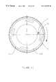
- FIG. 4A is a cross-sectional plan view through the spinning head of FIG. 3 showing the annular glass distribution plate.
- FIG. 4B is a view as in FIG. 4A showing an alternate form of distribution plate.
- FIG. 4C is a cross-sectional plan view through the spinning head of FIG. 4 showing a distribution plate pierced by holes.
- FIG. 5 is a side cross-sectional view of the gas burner located beneath the spinning head in FIG. 2 .
- molten glass from a forehearth 1 flows due to gravity through an electrically heated 90% platinum—10% rhodium alloy bushing 2 .
- Bushing 2 works as a sort of flow controlling device for molten glass.
- a molten glass stream 3 forms, gradually accelerating, and reducing in its diameter as it travels downwardly from bushing 2 .
- the glass stream 3 passes through a cut-out area 4 in fiberizer top plate 5 , and further moves down through annular cavity 6 . Cavity 6 is formed between the annular external (main) burner 7 and bearing housing 8 .
- the glass stream 3 continuing down, enters the rotating, open-from-the-top, conventional spinning head 10 .
- Conventional means such as an electric motor (not shown) with some step-up belt drive system, is used to drive spinning head 10 through mounting shaft 19 .
- Driven shaft 19 is supported by the bearing housing 8 .
- molten glass 3 A flows radially outwards, to the extrusion rim and then through a multiplicity of tiny holes or orifices. These holes are typically laser-drilled in the spinning head peripheral wall or extrusion rim 14 .
- the extruding glass emerges outside of the rim 14 as an array of primary fibres 15 .
- These primary fibres 15 on their way to become secondary fibres 18 , are subject to extensive attenuation by the combined action of the mass of fibre being spun by mechanical effect from the high speed rotating spinning head and aerodynamic drag on the fibre originating from both main burner 4 and blower 17 which together generate a gaseous flow field. Secondary fibre 18 forms the basis for further, subsequent, processing steps (not shown).
- the spinning head 20 of the invention structurally includes a spinning head floor 21 , an internal flow distribution flange 22 , a top flange 23 and a perforated peripheral rim wall, with a multiplicity of small orifices 44 or holes formed over the outer face surface of the rim wall.
- Internal flow distribution flange 22 has a set of circumferentially arranged slots or openings 25 A, 25 B (FIGS. 4A, 4 B). Slots 25 A, 25 B are positioned radially so as to periodically or cyclically align with the descending molten glass stream 3 .
- the function of the flow distribution flange 22 is to subdivide the glass stream, and the overall fibre forming function, into two or more, to some extent, independent and parallel, smaller glass fiber supply systems.
- Internal flange or plate 22 serves as a combined or integrated main molten glass supply flow divider and as a physical top and bottom chamber separator (solid wall). From a strictly structural point of view it also works as an annular stiffener rib for the peripheral extrusion rim wall 24 , so one can expect eventual disc face plastic deformation (creep) to be much less pronounced.
- top champer 27 temporarily ends, and the glass stream is admitted to the bottom disc area and lower chamber 26 through corresponding slot segment 25 A, 25 B.
- the whole glass stream chopping and top/bottom chamber feeding process cyclically repeats itself after that. Due to some additional factors such as the head's high rotational speed, stream deceleration during landing on a solid flange, inertia effects, the high viscosity of molten glass and the tendency for molten glass to stick or adhere to a hot metal surface, the real picture of stream chopping will not be exactly as described above, and can be reliably established only by experimental means.
- This invention is premised on the assumption that external conditions for attenuation or thinning of primary fibres 15 are not as favourable for those extruded from the bottom part of the fiberizing disc as they are for those created in the top part.
- This selected mass distribution ratio is easily achieved by simple mechanical means, namely by having circumferential slots 25 formed in internal flange 22 with a corresponding, appropriate, total circumferential coverage angle.
- the actual, preferred, circumferential slot coverage angle for a given percentage of total mass flow rate supplied to the bottom chamber may be determined experimentally for a given glass and given process operating conditions. It also depends on whether fewer, but longer circumferential slots, or more but shorter, circumferential slots are provided on the internal dividing flange 22 . It has been found that usually the total circumferential slot coverage angle has to be larger than the bottom chamber total pull rate fraction.
- This internal flow distributor device doesn't operate as a continuous molten glass stream splitter or divider. Instead, in principle, it operates as a main glass stream chopper, where at a given time instant glass is being supplied either to one chamber or the other, but not both at the same time. Due to this intermittent fashion of operation it is believed preferable to allow more than one feed period for a given chamber per revolution.
- FIG. 4B shows a flange 22 with four slots 25 B. Increasing the number of slots 25 B will reduce variations in the head or height H of glass in the chambers 26 , 27 and therefore will also smooth-out the differences in instantaneous pull rates per hole and resulting fibre diameters during the time interval between the subsequent feed periods into a given chamber.
- FIG. 4 C As an alternative to having a slotted distributor plate 22 a plate 22 A with a solid surface, interrupted by internal openings 41 may be provided as shown in FIG. 4 C.
- the centrifugally-forced radial movement of the glass over the plate surface towards the peripheral wall 24 directs a portion of the flowing glass 3 A to be intercepted by the series of holes 41 in the plate 22 A that divert glass 3 A into bottom chamber 26 .
- Glass flowing between the holes 41 is retained in top chamber 27 .
- Such holes can be additionally equipped with a raised and bevelled or otherwise shaped flow-diverters to make sure that at least a portion of glass flowing towards the slotted area has to divert into the bottom chamber 26 .
- An example of such a configuration is shown in U.S. Pat. No. 2,305,172.
- a spinning head of the described construction with a slotted or perforated internal dividing flange 22 serving as a glass partitioning means, can be considered to some extent as two separate spinning heads connected in parallel.
- the operation of one fiberizing chamber is to a degree independent of the other one, and it is possible to fiberize with different glass heads H in top and bottom chambers 26 , 27 .
- the amounts of molten glass admitted to both parts of the head are set in a predetermined ratio by use of a fixed glass partitioning means and this ratio doesn't change substantially with spinning head age or over its operating life time.
- an additional external source of heat is preferably provided to keep the spinning head floor area 21 hot enough for proper operation.
- bottom burner assembly 30 This primary objective of delivering sufficient amount of heat to the disc bottom floor 21 is fulfilled by a bottom burner assembly 30 .
- bottom heater means such as induction heaters, may be employed.
- the bottom heater means of preferred burner 30 form serves the following purposes:
- Bottom burner assembly 30 is held in place by means of clamping device 31 , attached directly to the fiberizing unit's top plate 5 (FIG. 2 ).
- a fuel-air (natural gas-air) mixture is delivered down through pipe 32 into bottom burner chamber 33 .
- Support pipe 32 is mounted inside hollow spinning head driving shaft 19 , co-axially with it.
- Gaseous combustible mixture flows out from burner chamber 33 through an array of small gas orifices 34 located in burner tip 35 . At the exit gas orifice 34 the mixture ignites and, in form of continuous circular flame, impinges upon the spinning head bottom 21 .
- Bottom burner has venting holes 36 for pressure equalization between the areas directly above and below the bottom burner structure, this also helps to stabilize the bottom burner flame. Also the chances of igniting combustible mixture inside bottom burner chamber 33 are slimmer since there is no stagnant air pocket right in contact with the hot spinning head bottom 21 to gradually, over time, heat and raise its temperature to the level sufficient to initiate the combustion process inside bottom burner chamber 33 .
- the bottom burner geometry just described has a closed structure (dish or bowl like) to simultaneously serve also as a bottom radiation shield for fiberizing spinning head bottom 21 . To some extent it also performs the function of a fibre veil stabilizer.
- a closed structure ish or bowl like
- a circular burner manifold is mechanically supported by and supplied with combustible mixture through some radial spokes connected to central supply and support pipe. This last design, however, doesn't help to reduce spinning head bottom radiative heat losses. It also is a much easier target for fibre build-up and accumulation.
Abstract
Description
Claims (7)
Priority Applications (3)
| Application Number | Priority Date | Filing Date | Title |
|---|---|---|---|
| US09/302,450 US6170298B1 (en) | 1999-04-30 | 1999-04-30 | Glass spinner with partitioned spinning head |
| CA002271514A CA2271514C (en) | 1999-04-30 | 1999-05-12 | Glass spinner with partitioned spinning head |
| GB9911601A GB2349383B (en) | 1999-04-30 | 1999-05-19 | Glass spinner with partition spinning head |
Applications Claiming Priority (1)
| Application Number | Priority Date | Filing Date | Title |
|---|---|---|---|
| US09/302,450 US6170298B1 (en) | 1999-04-30 | 1999-04-30 | Glass spinner with partitioned spinning head |
Publications (1)
| Publication Number | Publication Date |
|---|---|
| US6170298B1 true US6170298B1 (en) | 2001-01-09 |
Family
ID=23167781
Family Applications (1)
| Application Number | Title | Priority Date | Filing Date |
|---|---|---|---|
| US09/302,450 Expired - Lifetime US6170298B1 (en) | 1999-04-30 | 1999-04-30 | Glass spinner with partitioned spinning head |
Country Status (3)
| Country | Link |
|---|---|
| US (1) | US6170298B1 (en) |
| CA (1) | CA2271514C (en) |
| GB (1) | GB2349383B (en) |
Cited By (2)
| Publication number | Priority date | Publication date | Assignee | Title |
|---|---|---|---|---|
| US6793151B2 (en) | 2002-09-18 | 2004-09-21 | R&J Inventions, Llc | Apparatus and method for centrifugal material deposition and products thereof |
| US20050098670A1 (en) * | 2003-11-07 | 2005-05-12 | Michael Lasalle | Fiberizer thermocouple support frame |
Citations (10)
| Publication number | Priority date | Publication date | Assignee | Title |
|---|---|---|---|---|
| US1294909A (en) * | 1917-11-01 | 1919-02-18 | Barrett Co | Centrifugal process and device. |
| US3190736A (en) * | 1962-08-21 | 1965-06-22 | Johns Manville | Rotor for the forming of glass filaments |
| US3254482A (en) * | 1964-12-09 | 1966-06-07 | Owens Corning Fiberglass Corp | Apparatus for forming and processing fibers |
| US5312469A (en) * | 1992-03-25 | 1994-05-17 | Owens-Corning Fiberglas Technology Inc. | Centrifuging with protected fiberforming cones |
| US5482527A (en) * | 1994-09-20 | 1996-01-09 | Owens-Corning Fiberglas Technology, Inc. | Spinner apparatus for producing dual component fibers |
| EP0703196A1 (en) * | 1994-09-20 | 1996-03-27 | Owens-Corning Fiberglas Corporation | Spinner for producing dual-component fibers |
| US5523032A (en) * | 1994-12-23 | 1996-06-04 | Owens-Corning Fiberglas Technology, Inc. | Method for fiberizing mineral material with organic material |
| US5591459A (en) * | 1995-02-28 | 1997-01-07 | Owens Corning Fiberglas Technology, Inc. | Apparatus for reinforcing a fiber producing spinner |
| US5779760A (en) * | 1996-09-30 | 1998-07-14 | Owens Corning Fiberglas Technology, Inc. | Fiber manufacturing spinner |
| US5785996A (en) * | 1996-11-27 | 1998-07-28 | Owens Corning Fiberglas Technology, Inc. | Fiber manufacturing spinner and fiberizer |
-
1999
- 1999-04-30 US US09/302,450 patent/US6170298B1/en not_active Expired - Lifetime
- 1999-05-12 CA CA002271514A patent/CA2271514C/en not_active Expired - Fee Related
- 1999-05-19 GB GB9911601A patent/GB2349383B/en not_active Expired - Fee Related
Patent Citations (10)
| Publication number | Priority date | Publication date | Assignee | Title |
|---|---|---|---|---|
| US1294909A (en) * | 1917-11-01 | 1919-02-18 | Barrett Co | Centrifugal process and device. |
| US3190736A (en) * | 1962-08-21 | 1965-06-22 | Johns Manville | Rotor for the forming of glass filaments |
| US3254482A (en) * | 1964-12-09 | 1966-06-07 | Owens Corning Fiberglass Corp | Apparatus for forming and processing fibers |
| US5312469A (en) * | 1992-03-25 | 1994-05-17 | Owens-Corning Fiberglas Technology Inc. | Centrifuging with protected fiberforming cones |
| US5482527A (en) * | 1994-09-20 | 1996-01-09 | Owens-Corning Fiberglas Technology, Inc. | Spinner apparatus for producing dual component fibers |
| EP0703196A1 (en) * | 1994-09-20 | 1996-03-27 | Owens-Corning Fiberglas Corporation | Spinner for producing dual-component fibers |
| US5523032A (en) * | 1994-12-23 | 1996-06-04 | Owens-Corning Fiberglas Technology, Inc. | Method for fiberizing mineral material with organic material |
| US5591459A (en) * | 1995-02-28 | 1997-01-07 | Owens Corning Fiberglas Technology, Inc. | Apparatus for reinforcing a fiber producing spinner |
| US5779760A (en) * | 1996-09-30 | 1998-07-14 | Owens Corning Fiberglas Technology, Inc. | Fiber manufacturing spinner |
| US5785996A (en) * | 1996-11-27 | 1998-07-28 | Owens Corning Fiberglas Technology, Inc. | Fiber manufacturing spinner and fiberizer |
Cited By (5)
| Publication number | Priority date | Publication date | Assignee | Title |
|---|---|---|---|---|
| US6793151B2 (en) | 2002-09-18 | 2004-09-21 | R&J Inventions, Llc | Apparatus and method for centrifugal material deposition and products thereof |
| US20050082388A1 (en) * | 2002-09-18 | 2005-04-21 | R & J Inventions | Apparatus and method for centrifugal material deposition and products thereof |
| US7435152B2 (en) * | 2002-09-18 | 2008-10-14 | R & J Inventions Llc | Apparatus and method for centrifugal material deposition and products thereof |
| US20050098670A1 (en) * | 2003-11-07 | 2005-05-12 | Michael Lasalle | Fiberizer thermocouple support frame |
| US7210314B2 (en) | 2003-11-07 | 2007-05-01 | Certainteed Corporation | Fiberizer thermocouple support frame |
Also Published As
| Publication number | Publication date |
|---|---|
| GB2349383B (en) | 2001-08-22 |
| CA2271514C (en) | 2002-04-16 |
| GB2349383A (en) | 2000-11-01 |
| CA2271514A1 (en) | 2000-10-30 |
| GB9911601D0 (en) | 1999-07-21 |
Similar Documents
| Publication | Publication Date | Title |
|---|---|---|
| US3928009A (en) | Rotary forming unit for fine mineral fibers | |
| US2998620A (en) | Method and means for centrifuging curly fibers | |
| KR100188507B1 (en) | Method and apparatus for manufacturing mineral wool, and mineral wool produced thereby | |
| US4116656A (en) | Method of manufacturing fibers of inorganic material and apparatus for same | |
| US4433992A (en) | Process and apparatus for forming mineral fibers | |
| WO1996034834A1 (en) | Fiber manufacturing spinner and fiberizer | |
| EP0931027B1 (en) | Fiber manufacturing spinner | |
| KR100444927B1 (en) | Method and apparatus for producing mineral wool | |
| US4451276A (en) | Method and apparatus for glass fiberization | |
| US6170298B1 (en) | Glass spinner with partitioned spinning head | |
| EP0703196B1 (en) | Spinner for producing dual-component fibers | |
| US2980952A (en) | Apparatus for forming fibers | |
| US3177058A (en) | Apparatus for processing heatsoftenable materials | |
| US3013299A (en) | Method of and means for fiberization | |
| JPWO2004101459A1 (en) | Glass fiber manufacturing method and manufacturing apparatus | |
| US3265477A (en) | Apparatus for forming and collecting mineral fibers | |
| US3523774A (en) | Rotary apparatus for forming glass fibers | |
| US3077751A (en) | Method and apparatus for forming and processing fibers | |
| DK143127B (en) | METHOD AND APPARATUS FOR MANUFACTURING FIBERS OF THERMOPLASTIC MATERIAL | |
| CA2037426C (en) | Open bottomed spinner for mineral fibers | |
| HU213848B (en) | Process and apparatus for forming glass filaments | |
| US3048886A (en) | Apparatus for manufacturing mineral wool fibers | |
| US7685844B2 (en) | Method and device for producing mineral fibres | |
| US3058322A (en) | Apparatus for manufacturing mineral wool fibers | |
| US3607165A (en) | Glass fiber forming apparatus |
Legal Events
| Date | Code | Title | Description |
|---|---|---|---|
| AS | Assignment |
Owner name: OTTAWA FIBRE INC., CANADA Free format text: ASSIGNMENT OF ASSIGNORS INTEREST;ASSIGNORS:SKARZENSKI, JOSEPH;CSASTKIEWICZ, WITOLD S.;NASIOROWSKI, ANDRZEJ;AND OTHERS;REEL/FRAME:010077/0625 Effective date: 19990503 |
|
| STCF | Information on status: patent grant |
Free format text: PATENTED CASE |
|
| FPAY | Fee payment |
Year of fee payment: 4 |
|
| AS | Assignment |
Owner name: OFI HOLDINGS LTD., ONTARIO Free format text: AMALGAMATION;ASSIGNOR:OTTAWA FIBRE INC.;REEL/FRAME:016712/0717 Effective date: 20050829 |
|
| AS | Assignment |
Owner name: OFI HOLDINGS LTD., ONTARIO Free format text: ASSIGNMENT OF ASSIGNORS INTEREST;ASSIGNOR:OTTAWA FIBRE INC.;REEL/FRAME:016800/0404 Effective date: 20051020 |
|
| AS | Assignment |
Owner name: OTTAWA FIBRE LP, ONTARIO Free format text: ASSIGNMENT OF ASSIGNORS INTEREST;ASSIGNOR:OFI HOLDINGS LTD.;REEL/FRAME:017015/0181 Effective date: 20050901 |
|
| AS | Assignment |
Owner name: OTTAWA FIBRE LP, ONTARIO Free format text: CONFIRMATORY ASSIGNMENT;ASSIGNOR:FIBREGLASS HOLDINGS LTD. (FORMERLY KNOWN AS OFI HOLDINGS LTD.);REEL/FRAME:017025/0065 Effective date: 20060116 Owner name: FIBREGLASS HOLDINGS LTD., ONTARIO Free format text: CHANGE OF NAME;ASSIGNOR:OFI HOLDINGS LTD.;REEL/FRAME:017015/0958 Effective date: 20050906 Owner name: FIBREGLASS HOLDINGS LTD. (FORMERLY KNOWN AS OFI HO Free format text: CORRECTIVE AMENDMENT TO CONFIRMATORY U.S. PATENT ASSIGNMENT RECORDED AT REEL/FRAME 016800/0404;ASSIGNOR:OTTAWA FIBRE INC.;REEL/FRAME:017025/0058 Effective date: 20051231 |
|
| FPAY | Fee payment |
Year of fee payment: 8 |
|
| FPAY | Fee payment |
Year of fee payment: 12 |