US616632A - e y e a ii c ii - Google Patents
e y e a ii c ii Download PDFInfo
- Publication number
- US616632A US616632A US616632DA US616632A US 616632 A US616632 A US 616632A US 616632D A US616632D A US 616632DA US 616632 A US616632 A US 616632A
- Authority
- US
- United States
- Prior art keywords
- tube
- pitch
- tank
- kettle
- valve
- Prior art date
- Legal status (The legal status is an assumption and is not a legal conclusion. Google has not performed a legal analysis and makes no representation as to the accuracy of the status listed.)
- Expired - Lifetime
Links
- 239000011295 pitch Substances 0.000 description 46
- 239000007789 gas Substances 0.000 description 6
- 239000007788 liquid Substances 0.000 description 4
- 238000005336 cracking Methods 0.000 description 2
- 239000011339 hard pitch Substances 0.000 description 2
- 238000010438 heat treatment Methods 0.000 description 2
- 238000002844 melting Methods 0.000 description 2
- 239000000203 mixture Substances 0.000 description 2
- 230000000284 resting Effects 0.000 description 2
- 239000007921 spray Substances 0.000 description 2
- 239000000126 substance Substances 0.000 description 2
Images
Classifications
-
- B—PERFORMING OPERATIONS; TRANSPORTING
- B05—SPRAYING OR ATOMISING IN GENERAL; APPLYING FLUENT MATERIALS TO SURFACES, IN GENERAL
- B05B—SPRAYING APPARATUS; ATOMISING APPARATUS; NOZZLES
- B05B13/00—Machines or plants for applying liquids or other fluent materials to surfaces of objects or other work by spraying, not covered by groups B05B1/00 - B05B11/00
- B05B13/06—Machines or plants for applying liquids or other fluent materials to surfaces of objects or other work by spraying, not covered by groups B05B1/00 - B05B11/00 specially designed for treating the inside of hollow bodies
- B05B13/0627—Arrangements of nozzles or spray heads specially adapted for treating the inside of hollow bodies
- B05B13/0636—Arrangements of nozzles or spray heads specially adapted for treating the inside of hollow bodies by means of rotatable spray heads or nozzles
Definitions
- WITNESSES INVENTOR BY ATTQRNEY 114 means PETERS co, Puo-roLm-m. wAsumcj'ou, n. cy
- This invention relates to improvements in cask-pitchin g apparatuses generally,but more particularly to that form or kind of such apparatuses as I have described in my United States Patent No. 599,476, dated February 22, 1898.
- the apparatus described in this patent consists, briefly, of a kettle to receive the pitch, arranged over a suitable furnace and having below its bottom and preferably cast integrally with it one or more tanks to receive, through a valve-controlled inlet, pitch from the kettle.
- This tank, or each tank, if there be more than one, has an uprightoutlet-pipe with a spray-nozzle on its upper end to deliver the pitch in the form of spray into a cask supported on the cover of the kettle.
- the pitch is ejected from the tank by the admission of compressed air on it from some source of compressed air. So far as above described the apparatus is the same and operates the same as that described in my former patent. In operating such an apparatus a difficulty is apt to arise.
- the molten pitch left in the kettle after the pitching operation flows down into and fills the tank, and when the apparatus cools this mass of pitch in and filling the tank hardens. Consequently it is only with great care and skill that the apparatus can be reheated without creating in the tank such an internal pressure, due to expansion and to the generation of gases from the pitch, as will crack the walls of the full tank before the entire mass of pitch therein can melt.
- the purpose of the present invention which consists in providing the tank with a relief device for the expansion and the gen' erated gases, so that the latter may escape as generated until the entire mass of pitch shall have melted.
- the relief device which forms the subject of this-invention is designed to allow for expansion at the time of heating up the apparatus for operation again while the tank B contains, the hard pitch. Ordinarily under these conditions the tank will be absolutely full of the pitch, and it is necessary to provide relief.
- the preferred form of relief device (designated as a whole by G) will now be described.
- a tube 7b extends down through the cover of the kettle A and through the bottom 0 of the same, so as to open communication between the interior of the tank B and the outer air.
- This tube h will be secured permanently in position in the kettle.
- a vent-tube '5 which is adapted to fit into and he slipped down through the tube h, extends down into and nearly to the bottom of the tank B, as seen in Fig. 1.
- In the bottom of the tube t' is an tube 7L.
- valve-rod m Within the tube i is a valve-rod m, which has a conical valve m at its end to fit into a seat at the aperture j and close the latter. At its upper or outer end the rod m has a screw m which screws into the upper end of the tube 2' in seating the valve. It also has an eye m or some equivalent means of grasping it at its outer end.
- a relief device comprising a tube It, extending downinto the tank and open at its ends, means for closing the outer end of said tube h, a vent-tube i, which fits into the tube h and is adapted to extend down nearly to the bottom of the tank, said tube having a valve-seated aperture j in its lower end, and a valve-rod m, provided with a coned valve m, to close the aperture j, and a screw m to screw into the upper end of the vent-tube, substantially as set forth.
Description
No. 6l6,832. Patented Dec. 27, I898. H. BAUCH.
APPARATUS FOR PITCHING CASKS.
(Application filed Mar. 29, 1898.)
(No Model.)
|...Il| .IlllllL |||||||||l| llll.
WITNESSES INVENTOR BY ATTQRNEY 114: means PETERS co, Puo-roLm-m. wAsumcj'ou, n. cy
UNirnn Starts HENRY RAUOII,
NEXV YORK, N. Y.
APPARATUS FOR PITCHING CASKS.
SPECIFICATION forming part of Letters Patent No. 616,632, dated December 27, 1898-.
Application filed March 29, 1898.
To all whom, it may concern:
Be it known thatI, HENRY RAUCH,a citizen of the United States, residing in the borough of Manhattan and city, county, and State of New York,have invented certain new and useful Improvements in Apparatuses for Pitching Oasks, of which the following is a specification.
This invention relates to improvements in cask-pitchin g apparatuses generally,but more particularly to that form or kind of such apparatuses as I have described in my United States Patent No. 599,476, dated February 22, 1898. The apparatus described in this patent consists, briefly, of a kettle to receive the pitch, arranged over a suitable furnace and having below its bottom and preferably cast integrally with it one or more tanks to receive, through a valve-controlled inlet, pitch from the kettle. This tank, or each tank, if there be more than one, has an uprightoutlet-pipe with a spray-nozzle on its upper end to deliver the pitch in the form of spray into a cask supported on the cover of the kettle. The pitch is ejected from the tank by the admission of compressed air on it from some source of compressed air. So far as above described the apparatus is the same and operates the same as that described in my former patent. In operating such an apparatus a difficulty is apt to arise. The molten pitch left in the kettle after the pitching operation flows down into and fills the tank, and when the apparatus cools this mass of pitch in and filling the tank hardens. Consequently it is only with great care and skill that the apparatus can be reheated without creating in the tank such an internal pressure, due to expansion and to the generation of gases from the pitch, as will crack the walls of the full tank before the entire mass of pitch therein can melt. To obviate this danger of cracking the tank and to enable any ordinary workman to fire up under the kettle and operate the apparatus is the purpose of the present invention,which consists in providing the tank with a relief device for the expansion and the gen' erated gases, so that the latter may escape as generated until the entire mass of pitch shall have melted.
In the accompanying drawings an embodiment of the invention is illustrated as applied Serial No. 675,545, (No model.)
to an apparatus constructed in other-respects like that shown in my former patent.
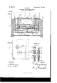
Figure l is a vertical mid-section of the apparatus in the plane indicated by line m in Fig. 2; and Fig. 2 is a fragmentary plan of the same. Fig. 3 illustrates the preferred form of the relief device.
A represents the kettle or reservoir set in walls X over a furnace Y. This kettle has a cover A with a covered opening a therein for feeding in the pitch, a screen I) to screen out foreign substances from the pitch, and one or more tanks B below the bottom 0 of the kettle to receive a predetermined quantity of the molten pitch, which latter flows down into the tank through a valve-controlled inlet (1. As here shown, there are four tanks B under the kettle, as indicated by the dotted, lines in Fig. 2, which show the positions of the partition-walls between the tanks. lVit-h four tanks four casks may be pitched at the same time. The compressed air is admitted to the tank by a pipe 6, and the pitch is discharged into the cask through an upright pipe f, having on its upper end a nose-nozzle g. All of the above is illustrated and fully described in my former patent, and the operation in detail will not need to be described herein. It will be sufficient to say that after the pitching operation of the dayis completed the apparatus is allowed to cool 0% and the mass of pitch .2' in the tank 13 becomes hard.
The relief device which forms the subject of this-invention is designed to allow for expansion at the time of heating up the apparatus for operation again while the tank B contains, the hard pitch. Ordinarily under these conditions the tank will be absolutely full of the pitch, and it is necessary to provide relief. The preferred form of relief device (designated as a whole by G) will now be described.
A tube 7b extends down through the cover of the kettle A and through the bottom 0 of the same, so as to open communication between the interior of the tank B and the outer air. This tube h will be secured permanently in position in the kettle. A vent-tube '5, which is adapted to fit into and he slipped down through the tube h, extends down into and nearly to the bottom of the tank B, as seen in Fig. 1. In the bottom of the tube t' is an tube 7L.
aperture 7', Fig. 3, and at its top it may have a flange k to rest on the top of the outer fixed This flange limits the depth to which the vent-tube i may enter the tank.
Within the tube i is a valve-rod m, which has a conical valve m at its end to fit into a seat at the aperture j and close the latter. At its upper or outer end the rod m has a screw m which screws into the upper end of the tube 2' in seating the valve. It also has an eye m or some equivalent means of grasping it at its outer end.
At the close of the days operations with the pitching apparatus and while the pitch is yet hot the workman inserts in the tube 71 the vent-tube t', the latter having in it the valverod m, with the valve thereonscrewed down to its seat, as seen in the view at the left in Fig. 3. "As the tube '1; fits the outer tube quite snugly, it acts as a plunger and forces the liquid pitch out from the tube h. The position of the relief device will now be as represented at the left in Fig. 1, the tip of the valve m resting on or being quite near down to the bottom of the tank BQ In the morning before starting a fire under the kettle the Workman unscrews the valve-rod and withdraws it. This he will not find diflicult, as the solidified pitch only has access for adherence to its exposed tip below the end of the vent-tube i; but this tube will itself be sealed fast by the pitch. The fire being now started, the pitch, melting first at the bottom of the tank, finds a vent for expansion and for the gases generated through the tube 2'. In a little while the pitch will be so softened that the vent-tube 2' can be withdrawn. After the pitch is thoroughly heated the tube h may be closed by a screw-cap n. (Seen detached in Fig. 3.)
I have given above the mode of using the relief device; but it will be understood that c into said tank and having an aperture and valve-seat at its lower end, means for closing the aperture at which said tube is inserted, and a valve-rod to extend through said tube, said rod being provided with a valve at its end to close the aperture in the tube, substantially as set forth.
2. The combination with a cask-pitching apparatus having a kettle A, a tank 13 below the bottom of the kettle and formed integrally therewith, and means for forcing the liquid pitch from said tank up into the cask, of a relief device comprising a tube It, extending downinto the tank and open at its ends, means for closing the outer end of said tube h, a vent-tube i, which fits into the tube h and is adapted to extend down nearly to the bottom of the tank, said tube having a valve-seated aperture j in its lower end, and a valve-rod m, provided with a coned valve m, to close the aperture j, and a screw m to screw into the upper end of the vent-tube, substantially as set forth.
In witness whereof I have hereunto signed my name, this 22d day of March, 1898, in the presence of two subscribing witnesses.
HENRY RAUCI-I. lVitnesses:
HENRY CONNETT, PETER A. Ross.
Publications (1)
| Publication Number | Publication Date |
|---|---|
| US616632A true US616632A (en) | 1898-12-27 |
Family
ID=2685241
Family Applications (1)
| Application Number | Title | Priority Date | Filing Date |
|---|---|---|---|
| US616632D Expired - Lifetime US616632A (en) | e y e a ii c ii |
Country Status (1)
| Country | Link |
|---|---|
| US (1) | US616632A (en) |
-
0
- US US616632D patent/US616632A/en not_active Expired - Lifetime
Similar Documents
| Publication | Publication Date | Title |
|---|---|---|
| US616632A (en) | e y e a ii c ii | |
| US1203512A (en) | Cleaning device. | |
| US977261A (en) | Valve-fitting. | |
| US551540A (en) | Liquid-dispensing apparatus | |
| US857674A (en) | Bottle-filling apparatus. | |
| US40347A (en) | Improved soda-water apparatus | |
| US615725A (en) | Philip lindemeyr | |
| US376471A (en) | Soda-water fountain | |
| US1695207A (en) | Milk pasteurizer | |
| US579629A (en) | William c | |
| US577784A (en) | Oil or gasolene can | |
| US572179A (en) | Bottle | |
| US95927A (en) | Improvement in cut-off nozzle for cans | |
| US599476A (en) | rauoh | |
| US977167A (en) | Bottle-stopper. | |
| US684923A (en) | Milk-can. | |
| US574075A (en) | Multiple syruping-machine | |
| US1451937A (en) | Device for the preservation and aseptic drawing off of liquids | |
| US1191484A (en) | Liquid measuring and dispensing device. | |
| US646185A (en) | Self-heating dinner-pail. | |
| US610521A (en) | bonafede | |
| US413471A (en) | zimmeemann | |
| US1043934A (en) | Non-refillable bottle. | |
| US106964A (en) | Improvement in apparatus for pitching barrels | |
| US504849A (en) | Soda-water apparatus |