US615744A - Tobacco-planter - Google Patents
Tobacco-planter Download PDFInfo
- Publication number
- US615744A US615744A US615744DA US615744A US 615744 A US615744 A US 615744A US 615744D A US615744D A US 615744DA US 615744 A US615744 A US 615744A
- Authority
- US
- United States
- Prior art keywords
- jaws
- plant
- tobacco
- valve
- planter
- Prior art date
- Legal status (The legal status is an assumption and is not a legal conclusion. Google has not performed a legal analysis and makes no representation as to the accuracy of the status listed.)
- Expired - Lifetime
Links
Images
Classifications
-
- A—HUMAN NECESSITIES
- A01—AGRICULTURE; FORESTRY; ANIMAL HUSBANDRY; HUNTING; TRAPPING; FISHING
- A01C—PLANTING; SOWING; FERTILISING
- A01C11/00—Transplanting machines
- A01C11/006—Other parts or details or planting machines
Definitions
- My invention relates to tobacco-planters and contemplates the provision of simple and reliable automatic plant-setting mechanism operative by and in concert with a water-discharging valve, as will be hereinafter fully described and claimed.
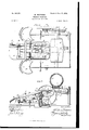
- Figure'l is a plan view of a tobacco-planter embracing my improvements.
- Fig. 2 is a longitudinal section taken in the plane indicated by line 2 2 of Fig. 1.
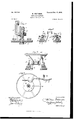
- Fig. 6 is a detail longitudinal section taken in the plane indicated by the line 6 6 of Fig. 1-.
- my improved planter comprises a suitable main frame A, traveling wheels B, supporting the same, a water barrel or tank G, carried by the frame, and a downwardlydisposed discharge-spout D, arranged in the longitudinal center of the frame and connected with the water-barrel.
- a rocking valve E designed to normally rest in a closed position and be opened at suitable intervals when the planter is in operation by one of the traveling wheels B through the medium of an interposed gear.
- the gear is best shown in Figs.
- crank a fixed to the valve, a disk I), fixed to Wheel 13 and having a plurality of equidistant lateral tappets c, a lever (Z, arranged to be en gaged and rocked by said tappets, a rockshaft 6, having a crank-arm f with a lateral projection 9, arranged to be engaged by the lever d, and also having an arm h, a bellcrank lover I, having one arm arranged to be engaged by the arm h of shaft 0, and a link j, connected to the other arm of said lever and arranged to engage the crank a of the valve, as best shown in Fig. 2.
- the connection between lever t' and link j is preferably an adjustable one, as shown, to permit of the throw of the valve being properly adjusted when necessary.
- the water-discharging spout D has its lower end arranged in a furrow-opener F, arranged between and connected to the forward por-' tion of two shoes G, which in turn are suitably connected to the main frame and are disposed at opposite sides of the longitudinal center of the machine.
- the furrow-opener is designed to serve the purpose its name implies, and the shoes are designed to press the wet earth about the plants after theyare set in the furrow in the manner common to tobacco-planters.
- H are seats connected to the main frame at opposite sides of the shoes G and designed to receive two attendants
- I are two baseirons arranged upon and connected to the shoes in such a manner as to permit of them being adjusted in an endwise direction thereon for a purpose presently described.
- This rock-shaft K carries two resilient plant-grasping jaws L and is designed to be actuated by the valve E through the medium of the crank a thereof and the pitman M, which is connected at one end to the said crank and is adjustably connected at its opposite end to an arm N of the rock-shaft, so as to permit of the throw of the said rockshaft and the jaws thereon being increased or diminished, as desired.
- a spring P connected to the pitman M and one of the irons I, serves to return the rock-shaft and jaws L to the position shown in Fig. 2 and normally hold the same in such position. It follows from this that the said spring will also serve to return the Valve E to and normally hold it in its closed position.
- Q is a plant-holder, which comprises two members connected to the water-discharge spout D and has for its purpose to receive and hold a plant until the same is engaged by the jaws L
- R are two cams, which have for their purpose to engage and move the jaws L together when the same are depressed, so as to enable said jaws to grasp a plant and set the same in the furrow formed by the opener F.
- the cams R are pivoted in body-plates S and are weighted, as indicated by 1), so as to normally rest in and reassume the position shown in Fig. at after the jaws L move out of engagement therewith.
- the body-plates S in turn are adjustably connected to the base-irons I, so as to permit of the cams B being moved in or out to regulate the extent of the movement of the jaws L toward each other.
- the body-plates S are also so connected to the base-irons as to permit of the cams B being raised or lowered when desired.
- the connection preferred consists of threaded bolts 0', taking through the baseirons and also through slots in the bod y-plates S, and two nuts .9 arranged below and one nut 25 arranged above each body-plate, as shown.
- T designates foot-rests for the attendants
- U designates a hand-rest, which is connected to uprights a, rising from the baseirons, as shown.
- the same may be accomplished by moving the base-irons I lengthwise on the shoes G and also by raising or lowering the uprights J, which, as before stated, are ad j ustably connected to the baseirons.
- my ll1V(- ⁇ l1ll0ll, ⁇ llftll I claim is- 1.
- a main frame provided with traveling wheels, a tank carried th ereby,a discharge-spout connected with the tank, a valve operative by one of the traveling wheels through the medium of an interposed gear, a plant-holder, plant-graspin g jaws, mechanism for depressing the jaws in concert wit-h the opening of the valve, and suitable means for moving the jaws together or toward each other during their downward movement, substantially as specified.
- a tobacco-planter the combination of a main frame provided with traveling wheels, shoes connected with said frame, a furrowopener connected to and arranged between the forward ends of the shoes, a tank arranged on the frame, a discharge-spout connected with the tank, a valve operative by one of the traveling wheels through the medium of an interposed gear, a plant-holder, plant-grasping jaws, mechanism connected with the valve for depressing the jaws in con cert with the opening of the valve, and suitable means for moving the jaws together or toward each other during their downward movement, substantially as specified.
- a tobacco-planter the combination of a main frame provided with traveling Wheels, a tank therein, a discharge-spout connected with the tank, a valve operative by one of the wheels through a suitable gear, plantgrasping jaws, mechanism for depressing the jaws in concert with the opening of the valve, and pivotally-mounted, weighted cams disposed on opposite sides of the jaws to press the same together or toward each other incident to their downward movement, substantially as specified.
- a tobacco-planter the combination of a plant-holder, resilient strips of metal form ing plant-grasping jaws, means for depressing said jaws, means for moving the jaws together or toward each other incident to their downward movement, means for returning the jaws to theirnorm al position,a-nd cushions arranged to engage the jaws when the same are in their normal position, substantially as specified.
- a tobacco-planter the combination of a main frame provided with traveling wheels, shoes connected with said frame, a furrowopener connected to and arranged between the forward ends of the shoes, a tank arranged on the frame, a discharge-spout connected with the tank and having its lower end arranged in the furrow-opener, a valve having a crank, a gear interposed between one of the traveling wheels and said crank, a rockshaft journaled in hearings on the shoes and having an arm connected with the crank of the Valve, a spring connecting said arm and one of the shoes, a plant-holder connected to the discharge-spout, plant-grasping jaws con-.
- a tobacco-planter the combination of a main frame provided with traveling wheels, shoes connected with said frame, a furrow- 35 opener connected to and arranged between the forward ends of the shoes, a tank arranged on the frame, a discharge-spout connected with the tank and having its lower end arranged in the furrow-opener, a valve having a crank, a I gear interposed between one of the traveling wheels and said crank, baseirons' adj ustably connected to the shoe, a rockshaft journaled in bearings on the base-irons and having an arm connected with the crank of the valve, a spring connecting said arm and one of the base-irons, a plant-holder connected to the discharge-spout, plant-grasping jaws connected to the rock-shaft, slides connected to the base-irons and adjustable at right angles thereto, and weighted cams pivotally mounted in said slides, substantially as specified.
Landscapes
- Life Sciences & Earth Sciences (AREA)
- Soil Sciences (AREA)
- Environmental Sciences (AREA)
- Soil Working Implements (AREA)
Description
No. 65,744. Patented Dec. 13, I898. W. PRETSMAN.
TOBACCDPLANTER.
[Application filed July 15, 1898.)
'2 sheets s'hee:
'(Nb Model.)
l'rcverd u?" THE N'cmms warns co.. mmaumu, WASN'NGTON, o. c.
vPatented Dec. I3, I898.
w PRETsMAN. TOBACCO PLANTER.
I (Application filed July 15. 1898.)
(No Model.) 2 Sheets-.$heet 2.
Int/6712??" m: mums PErERs co mum-drum, WASHINGTON, u. c.
NITED STATES PATENT OFFICE.
WILLIAM PRETSMAN, OF GREENVILLE, OHIO.
TOBACCO-PLANTER.
SPECIFICATION forming part of Letters Patent N 0. 615,744, dated December 13, 1898.
Application filed July 15,1898. Serial No. 686,086. (No model.)
To all whom it may concern.-
Be it known that I, WILLIAMPRETsMAN, a citizen of the United States, residing at Greenville, in the county of Darke and State of Ohio, have invented new and useful Improvements in Tobacco-Planters, of which the following is a specification.
My invention relates to tobacco-planters and contemplates the provision of simple and reliable automatic plant-setting mechanism operative by and in concert with a water-discharging valve, as will be hereinafter fully described and claimed.
In the accompanying drawings, Figure'l is a plan view of a tobacco-planter embracing my improvements. Fig. 2 is a longitudinal section taken in the plane indicated by line 2 2 of Fig. 1. Figs. 3, 4, and are detail transverse sections taken in the planesindicated by the lines 3 3, at 4, and 5 5, respectively, of Fig. 1. Fig. 6 is a detail longitudinal section taken in the plane indicated by the line 6 6 of Fig. 1-.
Similar letters of reference designate corresponding parts in all of the several views.
In common with tobacco planters at present in use my improved planter comprises a suitable main frame A, traveling wheels B, supporting the same, a water barrel or tank G, carried by the frame, and a downwardlydisposed discharge-spout D, arranged in the longitudinal center of the frame and connected with the water-barrel. In the said spout D is arranged a rocking valve E, designed to normally rest in a closed position and be opened at suitable intervals when the planter is in operation by one of the traveling wheels B through the medium of an interposed gear. The gear is best shown in Figs. 1, 2, and 6 and comprises a crank a, fixed to the valve, a disk I), fixed to Wheel 13 and having a plurality of equidistant lateral tappets c, a lever (Z, arranged to be en gaged and rocked by said tappets, a rockshaft 6, having a crank-arm f with a lateral projection 9, arranged to be engaged by the lever d, and also having an arm h, a bellcrank lover I, having one arm arranged to be engaged by the arm h of shaft 0, and a link j, connected to the other arm of said lever and arranged to engage the crank a of the valve, as best shown in Fig. 2. The connection between lever t' and link j is preferably an adjustable one, as shown, to permit of the throw of the valve being properly adjusted when necessary.
The water-discharging spout D has its lower end arranged in a furrow-opener F, arranged between and connected to the forward por-' tion of two shoes G, which in turn are suitably connected to the main frame and are disposed at opposite sides of the longitudinal center of the machine. The furrow-opener is designed to serve the purpose its name implies, and the shoes are designed to press the wet earth about the plants after theyare set in the furrow in the manner common to tobacco-planters.
H are seats connected to the main frame at opposite sides of the shoes G and designed to receive two attendants, and I are two baseirons arranged upon and connected to the shoes in such a manner as to permit of them being adjusted in an endwise direction thereon for a purpose presently described. .Connected to the said base-irons I, preferably in an adjustable manner, so as to permit them to be raised or lowered, are two uprights J, in which are journaled the ends of a rockshaft K. This rock-shaft K carries two resilient plant-grasping jaws L and is designed to be actuated by the valve E through the medium of the crank a thereof and the pitman M, which is connected at one end to the said crank and is adjustably connected at its opposite end to an arm N of the rock-shaft, so as to permit of the throw of the said rockshaft and the jaws thereon being increased or diminished, as desired. A spring P, connected to the pitman M and one of the irons I, serves to return the rock-shaft and jaws L to the position shown in Fig. 2 and normally hold the same in such position. It follows from this that the said spring will also serve to return the Valve E to and normally hold it in its closed position.
Q is a plant-holder, which comprises two members connected to the water-discharge spout D and has for its purpose to receive and hold a plant until the same is engaged by the jaws L, and R are two cams, which have for their purpose to engage and move the jaws L together when the same are depressed, so as to enable said jaws to grasp a plant and set the same in the furrow formed by the opener F. The cams R are pivoted in body-plates S and are weighted, as indicated by 1), so as to normally rest in and reassume the position shown in Fig. at after the jaws L move out of engagement therewith. The body-plates S in turn are adjustably connected to the base-irons I, so as to permit of the cams B being moved in or out to regulate the extent of the movement of the jaws L toward each other. The body-plates S are also so connected to the base-irons as to permit of the cams B being raised or lowered when desired. The connection preferred consists of threaded bolts 0', taking through the baseirons and also through slots in the bod y-plates S, and two nuts .9 arranged below and one nut 25 arranged above each body-plate, as shown.
T designates foot-rests for the attendants, and U designates a hand-rest, which is connected to uprights a, rising from the baseirons, as shown.
In the practical operation of the planter plants are placed by the attendants in the holder Q. As the machine advances the valve E is opened and the shaft K is rocked to de press the jaws L every time a tappet c of wheel B engages the lever d. The opening of the valve results in a quantity of water being discharged into the furrow formed by the opener F, and the depression of the jaws L results in their engaging the cams R and being pressed together or toward each other by the same. \Vhen so pressed together, the jaws L will grasp the plant and draw it down from the holder Q and set it in the furrow. At this time the jaws L will be disengaged from the cams R and springing apart will release the plant and leave the same in the furrow, in which position it will be fixed by reason of the shoes packing the moistened earth about it. Immediately after the jaws L spring apart to release the plant which they have set the spring Poperates through the medium of the mechanism described to close the valve E and raise the jaws L to their normal position above the cams R, which by reason of their being weighted, as indicated by p, assume and norm ally rest in the position shown in Fig. 4:.
It will be appreciated from the foregoing that in virtue of my improvements the water is always discharged into the furrow at points closely adjacent to the points at which the plants are set, with the result that the earth pressed about the plant is better able to hold the same, and at the same time the plant is watered.
hen it is desired to regulate the throw of the plant-grasping jaws L, the same may be accomplished by moving the base-irons I lengthwise on the shoes G and also by raising or lowering the uprights J, which, as before stated, are ad j ustably connected to the baseirons.
In order to prevent quivering or shaking of the plant-grasping jaws L when in their normal position, which is very injurious to the eyes of the operators, I provide the cushions V on the uprights 1b of the hand-grasp U. These cushions afford a hearing for the jaws when the same are in their normal position and effectually prevent quivering of said jaws for the reason stated.
In feeding plants to the holder Q, the operators bear with one hand on the rest U and place the plants with the other hand. Two operators or attendants are necessary because the machine is adapted to set four plants at each complete revolution of the traveling wheels, and a plant must be in the holder at each depression of the grasping-jaws.
Having thus described my ll1V(-}l1ll0ll,\\llftll I claim is- 1. In a tobacco-planter, the combination of a main frame provided with traveling wheels, a tank carried th ereby,a discharge-spout connected with the tank, a valve operative by one of the traveling wheels through the medium of an interposed gear, a plant-holder, plant-graspin g jaws, mechanism for depressing the jaws in concert wit-h the opening of the valve, and suitable means for moving the jaws together or toward each other during their downward movement, substantially as specified.
2. In a tobacco-planter, the combination of a main frame provided with traveling wheels, shoes connected with said frame, a furrowopener connected to and arranged between the forward ends of the shoes, a tank arranged on the frame, a discharge-spout connected with the tank, a valve operative by one of the traveling wheels through the medium of an interposed gear, a plant-holder, plant-grasping jaws, mechanism connected with the valve for depressing the jaws in con cert with the opening of the valve, and suitable means for moving the jaws together or toward each other during their downward movement, substantially as specified.
3. In a tobacco-planter, the combination of a main frame provided with traveling Wheels, a tank therein, a discharge-spout connected with the tank, a valve operative by one of the wheels through a suitable gear, plantgrasping jaws, mechanism for depressing the jaws in concert with the opening of the valve, and pivotally-mounted, weighted cams disposed on opposite sides of the jaws to press the same together or toward each other incident to their downward movement, substantially as specified.
4.. In a tobacco-planter, the combination of a plant-holder, plant-grasping jaws, a suitable means for depressing the plant-grasp ing jaws, and pivotally-mounted, weighted cams disposed on opposite sides of the jaws to press the same together or toward each other incident to their downward movement, substantially as specified.
5. In a tobacco-planter, the combination of resilient strips of metal forming plant-grasping jaws, and cushions arranged to engage the said strips when the same are in their normal position, substantially as specified.
6. In a tobacco-planter, the combination of a plant-holder, resilient strips of metal form ing plant-grasping jaws, means for depressing said jaws, means for moving the jaws together or toward each other incident to their downward movement, means for returning the jaws to theirnorm al position,a-nd cushions arranged to engage the jaws when the same are in their normal position, substantially as specified.
7. In a tobacco-planter, the combination of a main frame provided with traveling wheels, shoes connected with said frame, a furrowopener connected to and arranged between the forward ends of the shoes, a tank arranged on the frame, a discharge-spout connected with the tank and having its lower end arranged in the furrow-opener, a valve having a crank, a gear interposed between one of the traveling wheels and said crank, a rockshaft journaled in hearings on the shoes and having an arm connected with the crank of the Valve, a spring connecting said arm and one of the shoes, a plant-holder connected to the discharge-spout, plant-grasping jaws con-.
nected to the rock-shaft, and means for mov in g said jaws together incident to their downward movement, substantially as specified.
8. In a tobacco-planter, the combination of a main frame provided with traveling wheels, shoes connected with said frame, a furrow- 35 opener connected to and arranged between the forward ends of the shoes, a tank arranged on the frame, a discharge-spout connected with the tank and having its lower end arranged in the furrow-opener, a valve having a crank, a I gear interposed between one of the traveling wheels and said crank, baseirons' adj ustably connected to the shoe, a rockshaft journaled in bearings on the base-irons and having an arm connected with the crank of the valve, a spring connecting said arm and one of the base-irons, a plant-holder connected to the discharge-spout, plant-grasping jaws connected to the rock-shaft, slides connected to the base-irons and adjustable at right angles thereto, and weighted cams pivotally mounted in said slides, substantially as specified.
In testimony whereof I have hereunto set my hand in presence of two subscribing witnesses.
WILLIAM PRETSMAN. Witnesses: 1
VIRA I-I. MARTIN,
0. It. J OBEY.
Publications (1)
| Publication Number | Publication Date |
|---|---|
| US615744A true US615744A (en) | 1898-12-13 |
Family
ID=2684354
Family Applications (1)
| Application Number | Title | Priority Date | Filing Date |
|---|---|---|---|
| US615744D Expired - Lifetime US615744A (en) | Tobacco-planter |
Country Status (1)
| Country | Link |
|---|---|
| US (1) | US615744A (en) |
-
0
- US US615744D patent/US615744A/en not_active Expired - Lifetime
Similar Documents
| Publication | Publication Date | Title |
|---|---|---|
| US9006A (en) | Improvement in seed-planters | |
| US615744A (en) | Tobacco-planter | |
| US633216A (en) | Tobacco-planter. | |
| US32056A (en) | Improvement in corn-planners | |
| US22156A (en) | Improvement in seed-planters | |
| US242063A (en) | Signoe op one-half to william e | |
| US59559A (en) | Improvement in corn-planters | |
| US593493A (en) | Planting and seeding machine | |
| US63685A (en) | Andrew r | |
| US82853A (en) | lowth and thomas j | |
| US1311010A (en) | And edward m | |
| US132306A (en) | Improvement in corn-planters | |
| US995225A (en) | Automatic planter and check-rower. | |
| US594037A (en) | Planter | |
| US50246A (en) | Improvement in corn-planters | |
| US28142A (en) | Improvement in seeding-machines | |
| US357470A (en) | Corn-planter and marker | |
| US665008A (en) | Corn-planter attachment. | |
| US47518A (en) | Improvement in seeding-machines | |
| US9740A (en) | Improvement in seed-planters | |
| US132355A (en) | Improvement in corn-planters | |
| US1137933A (en) | Planter. | |
| US329203A (en) | Corn-planter | |
| US46480A (en) | Improved combined seeder, cultivator, and roller | |
| US23357A (en) | Improvement in seeding-machines |