US6153042A - Label removing method and apparatus - Google Patents
Label removing method and apparatus Download PDFInfo
- Publication number
- US6153042A US6153042A US09/190,139 US19013998A US6153042A US 6153042 A US6153042 A US 6153042A US 19013998 A US19013998 A US 19013998A US 6153042 A US6153042 A US 6153042A
- Authority
- US
- United States
- Prior art keywords
- label
- article
- cutting
- cut
- cutter
- Prior art date
- Legal status (The legal status is an assumption and is not a legal conclusion. Google has not performed a legal analysis and makes no representation as to the accuracy of the status listed.)
- Expired - Fee Related
Links
Images


Classifications
-
- G—PHYSICS
- G03—PHOTOGRAPHY; CINEMATOGRAPHY; ANALOGOUS TECHNIQUES USING WAVES OTHER THAN OPTICAL WAVES; ELECTROGRAPHY; HOLOGRAPHY
- G03D—APPARATUS FOR PROCESSING EXPOSED PHOTOGRAPHIC MATERIALS; ACCESSORIES THEREFOR
- G03D13/00—Processing apparatus or accessories therefor, not covered by groups G11B3/00 - G11B11/00
- G03D13/001—Cassette breaking apparatus
-
- G—PHYSICS
- G03—PHOTOGRAPHY; CINEMATOGRAPHY; ANALOGOUS TECHNIQUES USING WAVES OTHER THAN OPTICAL WAVES; ELECTROGRAPHY; HOLOGRAPHY
- G03B—APPARATUS OR ARRANGEMENTS FOR TAKING PHOTOGRAPHS OR FOR PROJECTING OR VIEWING THEM; APPARATUS OR ARRANGEMENTS EMPLOYING ANALOGOUS TECHNIQUES USING WAVES OTHER THAN OPTICAL WAVES; ACCESSORIES THEREFOR
- G03B17/00—Details of cameras or camera bodies; Accessories therefor
- G03B17/02—Bodies
-
- G—PHYSICS
- G03—PHOTOGRAPHY; CINEMATOGRAPHY; ANALOGOUS TECHNIQUES USING WAVES OTHER THAN OPTICAL WAVES; ELECTROGRAPHY; HOLOGRAPHY
- G03B—APPARATUS OR ARRANGEMENTS FOR TAKING PHOTOGRAPHS OR FOR PROJECTING OR VIEWING THEM; APPARATUS OR ARRANGEMENTS EMPLOYING ANALOGOUS TECHNIQUES USING WAVES OTHER THAN OPTICAL WAVES; ACCESSORIES THEREFOR
- G03B2219/00—Cameras
- G03B2219/02—Still-picture cameras
- G03B2219/04—Roll-film cameras
- G03B2219/045—Roll-film cameras adapted for unloading the film in the processing laboratory, e.g. disposable, reusable or recyclable cameras
-
- Y—GENERAL TAGGING OF NEW TECHNOLOGICAL DEVELOPMENTS; GENERAL TAGGING OF CROSS-SECTIONAL TECHNOLOGIES SPANNING OVER SEVERAL SECTIONS OF THE IPC; TECHNICAL SUBJECTS COVERED BY FORMER USPC CROSS-REFERENCE ART COLLECTIONS [XRACs] AND DIGESTS
- Y10—TECHNICAL SUBJECTS COVERED BY FORMER USPC
- Y10S—TECHNICAL SUBJECTS COVERED BY FORMER USPC CROSS-REFERENCE ART COLLECTIONS [XRACs] AND DIGESTS
- Y10S156/00—Adhesive bonding and miscellaneous chemical manufacture
- Y10S156/934—Apparatus having delaminating means adapted for delaminating a specified article
- Y10S156/935—Delaminating means in preparation for post consumer recycling
- Y10S156/936—Means for delaminating container component in preparation for recycling, e.g. glass bottle, plastic bottle
-
- Y—GENERAL TAGGING OF NEW TECHNOLOGICAL DEVELOPMENTS; GENERAL TAGGING OF CROSS-SECTIONAL TECHNOLOGIES SPANNING OVER SEVERAL SECTIONS OF THE IPC; TECHNICAL SUBJECTS COVERED BY FORMER USPC CROSS-REFERENCE ART COLLECTIONS [XRACs] AND DIGESTS
- Y10—TECHNICAL SUBJECTS COVERED BY FORMER USPC
- Y10T—TECHNICAL SUBJECTS COVERED BY FORMER US CLASSIFICATION
- Y10T156/00—Adhesive bonding and miscellaneous chemical manufacture
- Y10T156/11—Methods of delaminating, per se; i.e., separating at bonding face
- Y10T156/1142—Changing dimension during delaminating [e.g., crushing, expanding, warping, etc.]
-
- Y—GENERAL TAGGING OF NEW TECHNOLOGICAL DEVELOPMENTS; GENERAL TAGGING OF CROSS-SECTIONAL TECHNOLOGIES SPANNING OVER SEVERAL SECTIONS OF THE IPC; TECHNICAL SUBJECTS COVERED BY FORMER USPC CROSS-REFERENCE ART COLLECTIONS [XRACs] AND DIGESTS
- Y10—TECHNICAL SUBJECTS COVERED BY FORMER USPC
- Y10T—TECHNICAL SUBJECTS COVERED BY FORMER US CLASSIFICATION
- Y10T156/00—Adhesive bonding and miscellaneous chemical manufacture
- Y10T156/11—Methods of delaminating, per se; i.e., separating at bonding face
- Y10T156/1168—Gripping and pulling work apart during delaminating
- Y10T156/1179—Gripping and pulling work apart during delaminating with poking during delaminating [e.g., jabbing, etc.]
-
- Y—GENERAL TAGGING OF NEW TECHNOLOGICAL DEVELOPMENTS; GENERAL TAGGING OF CROSS-SECTIONAL TECHNOLOGIES SPANNING OVER SEVERAL SECTIONS OF THE IPC; TECHNICAL SUBJECTS COVERED BY FORMER USPC CROSS-REFERENCE ART COLLECTIONS [XRACs] AND DIGESTS
- Y10—TECHNICAL SUBJECTS COVERED BY FORMER USPC
- Y10T—TECHNICAL SUBJECTS COVERED BY FORMER US CLASSIFICATION
- Y10T156/00—Adhesive bonding and miscellaneous chemical manufacture
- Y10T156/19—Delaminating means
-
- Y—GENERAL TAGGING OF NEW TECHNOLOGICAL DEVELOPMENTS; GENERAL TAGGING OF CROSS-SECTIONAL TECHNOLOGIES SPANNING OVER SEVERAL SECTIONS OF THE IPC; TECHNICAL SUBJECTS COVERED BY FORMER USPC CROSS-REFERENCE ART COLLECTIONS [XRACs] AND DIGESTS
- Y10—TECHNICAL SUBJECTS COVERED BY FORMER USPC
- Y10T—TECHNICAL SUBJECTS COVERED BY FORMER US CLASSIFICATION
- Y10T83/00—Cutting
- Y10T83/04—Processes
- Y10T83/0448—With subsequent handling [i.e., of product]
- Y10T83/0467—By separating products from each other
-
- Y—GENERAL TAGGING OF NEW TECHNOLOGICAL DEVELOPMENTS; GENERAL TAGGING OF CROSS-SECTIONAL TECHNOLOGIES SPANNING OVER SEVERAL SECTIONS OF THE IPC; TECHNICAL SUBJECTS COVERED BY FORMER USPC CROSS-REFERENCE ART COLLECTIONS [XRACs] AND DIGESTS
- Y10—TECHNICAL SUBJECTS COVERED BY FORMER USPC
- Y10T—TECHNICAL SUBJECTS COVERED BY FORMER US CLASSIFICATION
- Y10T83/00—Cutting
- Y10T83/202—With product handling means
- Y10T83/2074—Including means to divert one portion of product from another
-
- Y—GENERAL TAGGING OF NEW TECHNOLOGICAL DEVELOPMENTS; GENERAL TAGGING OF CROSS-SECTIONAL TECHNOLOGIES SPANNING OVER SEVERAL SECTIONS OF THE IPC; TECHNICAL SUBJECTS COVERED BY FORMER USPC CROSS-REFERENCE ART COLLECTIONS [XRACs] AND DIGESTS
- Y10—TECHNICAL SUBJECTS COVERED BY FORMER USPC
- Y10T—TECHNICAL SUBJECTS COVERED BY FORMER US CLASSIFICATION
- Y10T83/00—Cutting
- Y10T83/647—With means to convey work relative to tool station
- Y10T83/6572—With additional mans to engage work and orient it relative to tool station
- Y10T83/6576—By opposed lateral guide means
-
- Y—GENERAL TAGGING OF NEW TECHNOLOGICAL DEVELOPMENTS; GENERAL TAGGING OF CROSS-SECTIONAL TECHNOLOGIES SPANNING OVER SEVERAL SECTIONS OF THE IPC; TECHNICAL SUBJECTS COVERED BY FORMER USPC CROSS-REFERENCE ART COLLECTIONS [XRACs] AND DIGESTS
- Y10—TECHNICAL SUBJECTS COVERED BY FORMER USPC
- Y10T—TECHNICAL SUBJECTS COVERED BY FORMER US CLASSIFICATION
- Y10T83/00—Cutting
- Y10T83/647—With means to convey work relative to tool station
- Y10T83/6584—Cut made parallel to direction of and during work movement
- Y10T83/6603—Tool shiftable relative to work-conveying means
Definitions
- the present invention relates to a label removing method and apparatus. More particularly, the present invention relates to a label removing method and apparatus for removal of a label which is wound about an article in a belt-shape and adhered to the article.
- a vessel or an article formed from plastic material or glass is provided with a label in various manners.
- a labeling structure in which a label has a front surface printed with patterns and information, and a back surface coated with adhesive agent, and is wound about the center of the article in a manner one distal end of the label is overlapped on the other.
- the labeling structure is advantageous in the small amount of the covering material in use, and thus a reduced packaging cost.
- the labeling structure can reduce the size of the covered shape of the material, to reduce its space required in stores where a great numbers of bottles or the like are displayed commercially.
- the vessel or article after being used is withdrawn collectively by dealers or manufacturers in consideration of effective use of limited resource, and protection of environment. After the label is peeled, the article is crushed and pelleted to be reused as raw material. If the article is safe without damages, it is provided with a new label and recycled.
- an object of the present invention is to provide a label removing method and apparatus in which a label can be easily peeled from an article efficiently, by creating a label portion to be chucked reliably.
- a label is wound about an article in a belt-shape, and at least partially adhered to the article.
- the label is cut in a predetermined cutting direction crosswise to a winding direction of the label, to form first and second cut ends on the label.
- the first cut end is pushed open away from the article. After the first cut end is pushed open, the first cut end and the article are moved relative to one another, so as to peel the label from the article.
- the article is a housing of a lens-fitted photo film unit (i.e., a camera).
- a lens-fitted photo film unit i.e., a camera
- a cutter cuts the label in a predetermined cutting direction crosswise to a winding direction of the label, to form first and second cut ends on the label.
- a spreader is disposed to be offset rearwards from the cutter in the cutting direction, and to protrude in the winding direction from the cutter, for pushing open the first cut end away from the article.
- a peeler moves the first cut end and the article relative to one another after the first cut end is pushed open, so as to peel the label from the article.
- a conveyor conveys the article in the cutting direction relative to the cutter, so as to cut the label.
- the cutter and the spreader are constituted by a single knife blade.
- the knife blade further includes a shank portion disposed to extend rearwards from the spreader in the cutting direction, at least the shank portion in the knife blade being flexed by the article when the cutter is pressed against the article.
- the cutter includes an advancing end, which is narrow, for passing between the label and the article in an advance position.
- a cutting portion is disposed to extend rearwards from the advancing end in the cutting direction, and to protrude opposite to the spreader in the winding direction, and has an inclined edge inclined relative to the cutting direction, for cutting the label in a cutting position, the cutting position being offset from the advance position.
- the article includes a substantially straight groove, formed to extend in the cutting direction, disposed in the advance position, for receiving insertion of the advancing end, to facilitate cutting of the label.
- the peeler includes a chuck for capturing the first cut end, and for moving away from the article.
- the peeler includes a pusher member for pushing the first cut end away from the article in the winding direction.
- the label can be easily peeled from the article efficiently.
- FIG. 1 is a front perspective illustrating a lens-fitted photo film unit
- FIG. 2 is a rear perspective illustrating the lens-fitted photo film unit
- FIG. 3 is a plan illustrating a label of the lens-fitted photo film unit
- FIG. 4 is a rear perspective illustrating the lens-fitted photo film unit with a knife blade and a passageway for peeling
- FIG. 5 is a perspective illustrating the knife blade
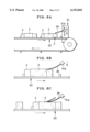
- FIG. 6A is an explanatory view in elevation, illustrating a label peeling apparatus
- FIG. 6B is an explanatory view in elevation, illustrating a state of the label peeling apparatus where the knife blade is about to cut the label;
- FIG. 6C is an explanatory view in elevation, illustrating a state where the knife blade is cutting the label
- FIG. 7 is a side elevation, partially broken, illustrating a relationship between the knife blade and the lens-fitted photo film unit having a straight groove
- FIG. 8 is an explanatory view in perspective, illustrating a relationship between a pusher member and a cut end of the label
- FIG. 9 is an explanatory view in perspective, illustrating the lens-fitted photo film unit, a peeler chuck, and its relevant construction
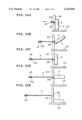
- FIG. 10A is an explanatory view in elevation, illustrating a state where the peeler chuck initially chucks the cut end;
- FIGS. 10B and 10C are explanatory views in elevation, illustrating states where the peeler chuck is peeling the label
- FIG. 10D is an explanatory view in elevation, illustrating a state of the finish of the label peeling.
- FIG. 10E is an explanatory view in elevation, illustrating a state where the chuck finally separates the label from a housing of the lens-fitted photo film unit.
- FIGS. 1 and 2 a lens-fitted photo film unit 2 is depicted.
- the lens-fitted photo film unit 2 is constituted of a housing 3 and a label or sticker 4.
- the housing 3 accommodates a mechanism for taking an exposure, and is preloaded with photo film.
- the housing 3 constitutes an article to be unwrapped in the present invention, and has a shape of a rectangular parallelepipedic prism.
- the label 4 is attached to the housing 3, and has a printed decorative pattern. Adhesive agent is applied to the whole or edges of the back surface of the label 4, to attach the label 4 to the housing 3.
- the label 4 is wound a bout the center of the housing 3 in a belt shape.
- the label 4 is formed from paper or a thin plastic sheet. Of course any of suitable materials may be selected as desired in the form of the label 4 as a thin sheet.
- the inside of the housing 3 has a cassette holder chamber (not shown) and a roll chamber (not shown).
- the cassette holder chamber contains a cassette shell of a photo film cassette.
- the roll chamber contains a roll of photo film, which is drawn out of the cassette shell.
- a left portion of the front of the housing 3 has a grip 7, which is shaped to cover the curved shape of the front of the cassette holder chamber containing the cassette shell.
- the right portion of the front of the housing 3 has a flash emitter window 5 and a flash charger button 6, which is depressible to start charging of a flash device.
- a projecting portion 9 In the center of the housing 3, there are a projecting portion 9 and a viewfinder window 10.
- the projecting portion 9 is so shaped as to cover internal elements including the shutter mechanism and a taking lens 8.
- a shutter button 12 is formed on the top of the housing 3.
- a counter window 13 is formed to keep a part of a counter disk (not shown) uncovered for indicating the number of remaining available frames of the photo film.
- the label 4 has a number of openings, through which the viewfinder window 10, the counter window 13 and the like appear externally.
- FIG. 3 an outer surface of the label 4 is depicted.
- the label 4 has the openings for the projecting portion 9 and the viewfinder window 10.
- An overlapping portion 15 is disposed on one end of the label 4.
- a bottom portion 16 is disposed on a remaining end of the label 4 to cover a bottom face of the housing 3.
- the bottom portion 16 is overlapped on the overlapping portion 15 on the bottom face of the housing 3, and attached to it with the adhesive agent.
- a rear portion 17 is used to cover the rear of the housing 3.
- the perforation train 19 defines a predetermined cutting direction.
- the perforation train 19 extends in the width direction of the spread shape of the label 4, from its one lateral edge 4a to the other lateral edge 4b.
- a perforation train 21 is also formed for the purpose of opening a bottom lid 26 for the purpose of removal of a photo film cassette from the housing 3.
- FIG. 2 the bottom face of the lens-fitted photo film unit is depicted.
- the label 4 is indicated by the phantom line.
- a bottom lid 25 closes the roll chamber light-tightly.
- the bottom lid 26 closes the cassette holder chamber light-tightly. Both of the bottom lids 25 and 26 are partially covered by the label 4, and prevented from opening incidentally.
- the straight groove 27 In the rear of the housing 3, there is a straight groove 27 disposed near to a bottom side of the rear.
- the straight groove 27 extends in the width direction of the label 4.
- the center of the straight groove 27 is covered by the label 4 with its both ends exposed beside the label 4.
- the straight groove 27 operates for ensuring insertion of a knife blade 36 between the housing 3 and the label 4 to facilitating removal of the label.
- One longer side 28 of the housing 3 defined between its rear face and bottom face is provided with a notch 30, for the purpose of peeling the label.
- the notch 30 has a notch bottom face 30a, which is inclined to decrease a depth in a direction perpendicular to the perforation train 19.
- the lens-fitted photo film unit 2 is forwarded to a photo laboratory without being disassembled.
- the bottom lid 26 is opened to remove the photo film cassette, to subject the photo film to photofinishing operation of development and printing.
- the lens-fitted photo film unit 2 from which the photo film cassette is removed is withdrawn by a manufacturer having produced it originally.
- the label 4 is removed from the housing 3 by the removing operation, which will be described later.
- the housing 3 without the label 4 is disassembled into various parts, which are inspected in various aspects. Parts, which are determined acceptable, are reused as parts of new lens-fitted photo film units. Parts, which are determined unacceptable, are crushed, pelleted and melted, to be used for raw material for new lens-fitted photo film units.
- FIG. 4 A construction suitable for peeling the label 4 from the housing 3 is now described.
- the label is being cut in its width direction.
- the knife blade 36 is disposed in a position along the passageway 35, for cutting the perforation train 19 while the lens-fitted photo film unit 2 is conveyed, and for pushing open the label 4 away from the housing 3 at a small width along the perforation train 19.
- the knife blade 36 is secured to a shifter 51, and shifted up and down in the position of the lens-fitted photo film unit 2.
- the knife blade 36 includes an advancing end 36a, a cutting portion 36b, and a spreader 36c.
- the advancing end 36a is bent, and caused to enter the straight groove 27.
- the cutting portion 36b cuts the label 4 along the perforation train 19.
- the spreader 36c after the cutting operation of the cutting portion 36b, shifts away the cut ends of the label 4 from the housing 3 to a predetermined small amount, for the purpose of causing one of the cut ends to be captured by a chuck of a label peeler device, which will be described later.
- the advancing end 36a has a bend angle ⁇ of 5-10°.
- the knife blade 36 has a thickness t of approximately 0.5 mm.
- the knife blade 36 consists of a flexible resilient plate with a small thickness, for example SUB steel (spring steel), SK steel or the like.
- a surface of the knife blade 36 is provided with a great number of narrow grooves in the longitudinal direction of the knife blade 36, in order to avoid cutting errors by preventing itself from being stuck on the adhesive-coated surface of the label 4 in the course of cutting the label 4.
- the surface of the knife blade 36 can be smoothly finished for the purpose of reliable avoidance of such cutting errors.
- the knife blade 36 may be coated with teflon, or provided with minute patterns of projections or recesses.
- surface active agent may be applied to the surface of the knife blade 36 to reduce resistance.
- FIGS. 6A-6C the lens-fitted photo film unit 2 is placed on a conveyor 52.
- a chuck 51a with the knife blade 36 comes down, so that the knife blade 36 is pressed against the rear of the housing 3, and flexed resiliently. See FIG. 6B.
- the lens-fitted photo film unit 2 is further conveyed by the conveyor 52, so that the cutting portion 36b of the knife blade 36 cuts the label 4 along the perforation train 19.
- the spreader 36c peels the label 4 at a regular width from the housing 3, to form a cut end 17a of the label 4. See FIG. 8.
- FIG. 8 one preferred embodiment for peeling the label is depicted.
- a pusher member 37 of a peeler in a stick shape is inserted into the notch 30 in contact with the notch bottom face 30a.
- a pusher end 37a of the pusher member 37 pushes a back surface of the rear portion 17. Consequently the pusher member 37 presses and peels the cut end 17a having been moved away from the housing 3 by the spreader 36c to the small extent.
- any suitable structure may be used for turning up the cut end 17a.
- compressed air may be applied to the back surface of the cut end 17a to move it away from the housing 3.
- a plate-shaped guide member, a roller or any device may be pressed against the cut end 17a to provide the cut end 17a with an inclination of being turned up away from the housing 3.
- a compressor of air may be used to suck the surface of the label 4 to turn up the cut end 17a away from the housing 3.
- a label peeler device is constituted by a pair of wall members 40 and 41, a support tray 42 and a peeler chuck 43.
- the wall members 40 and 41 are disposed erectly on the support tray 42 at an interval which is greater than a width of the label 4 and smaller than a range of the housing 3 in the width direction of the label 4.
- the peeler chuck 43 captures the cut end 17a, and moves in the arrow direction to pull it from between the wall members 40 and 41.
- the peeler chuck 43 is constituted by plates 46 and 47.
- the housing 3 is pulled to the wall members 40 and 41 when the peeler chuck 43 is moved.
- the wall members 40 and 41 keep the housing 3 from moving together with the peeler chuck 43. Pulling force of the peeler chuck 43 causes the housing 3 to turn in contact with the wall members 40 and 41, so as to peel the label 4 from the housing 3.
- the housing 3 When the housing 3 is turned, the housing 3 is forcibly rubbed on the wall members 40 and 41. Accordingly the wall members 40 and 41 are provided with smooth surfaces having low friction to contact the housing 3, for the purpose of reducing friction between the housing 3 and the wall members 40 and 41. It is possible to turn t h e housing 3 at high speed and smoothly, and prevent the housing 3 from being ground, damaged, and the label 4 from being broken.
- a horizontally arranged guide rod 39 can be used between the wall members 40 and 41.
- the cut end 17a is moved in contact with the guide rod 39 by the peeler chuck 43, so that the label 4 is transferred while supported on the guide rod 39.
- the label 4 is kept regular without being entangled.
- the lens-fitted photo film unit 2 is placed on the support tray 42.
- the peeler chuck 43 captures the cut end 17a between the wall members 40 and 41 as depicted in FIG. 10A.
- the peeler chuck 43 is moved in the arrow direction to pull the label 4.
- pulling force to the housing 3 is exerted to keep the housing 3 in contact with the wall members 40 and 41.
- the housing 3 is turned over behind the wall members 40 and 41 until the label 4 is peeled away at a high speed.
- FIG. 10E the housing 3 drops on the support tray 42 in such a direction that its front is directed upwards.
- a pair of nip rollers can be disposed to nip the cut end 17a, and can be driven to pull the cut end 17a.
- a conveyor belt having an adhesive surface may be used to stick on the cut end 17a, to pull and peel it.
- a suction pipe can be used to pull the cut end 17a by use of suction air.
- the cut end 17a can be wound on a spindle and pulled by rotation of the spindle.
- the article from which the label 4 is to be removed is the housing 3 of the lens-fitted photo film unit.
- the label 4 may be removed from a glass bottle, a PET bottle or other vessels to be recycled or reused. Such a bottle or vessels may be formed from any materials including plastic or glass.
- the label 4 may be removed from a vessel of any shapes, cylindrical, prismatic or the like. Such a vessel may have angular corners, and may have recesses or projections.
- a label may be removed from a cassette shell of a photo film cassette. Such a cassette shell may be formed from plastic material.
- the label may be heated by a heater, or else immersed in hot water, aqueous solution of alkali or other suitable liquid, for the purpose of weakening the adhesion.
- the label or the adhesive agent has a characteristic of coming to have weaker adhesion in response to ultraviolet rays or low temperature or high temperature, it is possible to apply ultraviolet rays to the label, or to apply hot or cool air to it.
- the adhesive agent is provided for the whole or edges of the back surface of the label 4.
- adhesive agent may be provided in any of suitable partial regions predetermined on the back surface of the label 4, in consideration of various purposes.
- the cut end of the label is moved away from the housing of the lens-fitted photo film unit.
- the housing of the lens-fitted photo film unit may be forcibly pulled away from the cut end of the label while the cut end is held in a stationary manner.
- the perforation train 19 is formed in the label 4 in a position offset from the straight groove 27 where the cutter cuts the label 4.
- the perforation train 19 may formed in the label 4 in a position directly along the straight groove 27.
Abstract
Description
Claims (31)
Applications Claiming Priority (2)
| Application Number | Priority Date | Filing Date | Title |
|---|---|---|---|
| JP9310675A JPH11138665A (en) | 1997-11-12 | 1997-11-12 | Method and apparatus for peeling label |
| JP9-310675 | 1997-11-12 |
Publications (1)
| Publication Number | Publication Date |
|---|---|
| US6153042A true US6153042A (en) | 2000-11-28 |
Family
ID=18008108
Family Applications (1)
| Application Number | Title | Priority Date | Filing Date |
|---|---|---|---|
| US09/190,139 Expired - Fee Related US6153042A (en) | 1997-11-12 | 1998-11-12 | Label removing method and apparatus |
Country Status (2)
| Country | Link |
|---|---|
| US (1) | US6153042A (en) |
| JP (1) | JPH11138665A (en) |
Cited By (10)
| Publication number | Priority date | Publication date | Assignee | Title |
|---|---|---|---|---|
| US6381409B1 (en) * | 1998-10-20 | 2002-04-30 | Fuji Photo Film Co., Ltd. | Method of disassembling lens-fitted photo film unit and disassembling apparatus therefor |
| US6522836B2 (en) * | 1995-07-19 | 2003-02-18 | Fuji Photo Film Co., Ltd. | Lens-fitted photo film unit having a recess and ridges in a housing thereof |
| US6678471B2 (en) * | 1999-03-12 | 2004-01-13 | Fuji Photo Film Co., Ltd. | Camera and wrapping sheet therefor |
| US20060005931A1 (en) * | 2004-05-06 | 2006-01-12 | Rocky Sherman | Label removing tool |
| US20080121335A1 (en) * | 2006-11-29 | 2008-05-29 | Nitto Denko Corporation | Method for attaching and peeling pressure-sensitive adhesive sheet, and attaching apparatus of pressure-sensitive adhesive sheet and peeling apparatus of pressure-sensitive adhesive sheet |
| US20080289763A1 (en) * | 2007-05-21 | 2008-11-27 | Beijing Boe Optoelectronics Technology Co., Ltd. | Striping apparatus and striping method |
| US20090229765A1 (en) * | 2008-03-13 | 2009-09-17 | Ngk Insulators, Ltd. | Automatic mask peeling apparatus |
| US20090294039A1 (en) * | 2008-05-27 | 2009-12-03 | Heidelberger Druckmaschinen Ag | Film Transfer Apparatus, Cassette for a Film Transfer Apparatus and Method for Operating a Film Transfer Apparatus |
| US20140060747A1 (en) * | 2012-09-05 | 2014-03-06 | Krones Ag | Method and Device for Recycling Labeled Plastic Articles |
| US8932706B2 (en) | 2005-10-27 | 2015-01-13 | Multi-Color Corporation | Laminate with a heat-activatable expandable layer |
Citations (12)
| Publication number | Priority date | Publication date | Assignee | Title |
|---|---|---|---|---|
| US3750504A (en) * | 1970-12-03 | 1973-08-07 | Aluminum Ag Corp | Method for the unpacking of cylindrical bodies interconnected groupwise by bands, and device for the performance thereof |
| US3889442A (en) * | 1972-03-13 | 1975-06-17 | Platmanufaktur Ab | Method of and device for removing a shrinkable plastic wrapping from a number of units, e.g. bottles, forming a substantially parallelepipedical body |
| US4717442A (en) * | 1983-06-21 | 1988-01-05 | Metal Box Public Limited Company | Apparatus for removing labels or carriers from containers |
| US4834826A (en) * | 1986-05-19 | 1989-05-30 | Gunze Kabushiki Kaisha | Method of an apparatus for cutting heat-shrinkable labels by melting |
| JPH06106150A (en) * | 1992-06-11 | 1994-04-19 | Alfill Getraenketechnik Gmbh | Device for peeling off label from container |
| US5442851A (en) * | 1992-09-08 | 1995-08-22 | Automated Label Systems Company | Delabelling apparatus |
| JPH0954399A (en) * | 1995-08-14 | 1997-02-25 | Fuji Photo Film Co Ltd | Film unit with lens and peeling method of outside case |
| US5685053A (en) * | 1995-05-24 | 1997-11-11 | Illinois Tool Works Inc. | Delabeling method |
| US5725349A (en) * | 1996-03-26 | 1998-03-10 | Garvey Corporation | Method and apparatus for removing shrinkwrap from a package of bottles |
| US5758362A (en) * | 1994-10-11 | 1998-06-02 | Focke & Co., (Gmbh & Co) | Process and device for handling stacks of blanks having wrappings |
| US5885401A (en) * | 1994-06-01 | 1999-03-23 | Krones Ag Hermann Kronseder Maschinenfabrik | Process and an apparatus for removing shrunk-on sleeves or all-round labels from vessels |
| US5933658A (en) * | 1995-07-19 | 1999-08-03 | Fuji Photo Film Co., Ltd. | Lens-fitted photo film unit, having a recess and ridges in a housing thereof |
-
1997
- 1997-11-12 JP JP9310675A patent/JPH11138665A/en active Pending
-
1998
- 1998-11-12 US US09/190,139 patent/US6153042A/en not_active Expired - Fee Related
Patent Citations (13)
| Publication number | Priority date | Publication date | Assignee | Title |
|---|---|---|---|---|
| US3750504A (en) * | 1970-12-03 | 1973-08-07 | Aluminum Ag Corp | Method for the unpacking of cylindrical bodies interconnected groupwise by bands, and device for the performance thereof |
| US3889442A (en) * | 1972-03-13 | 1975-06-17 | Platmanufaktur Ab | Method of and device for removing a shrinkable plastic wrapping from a number of units, e.g. bottles, forming a substantially parallelepipedical body |
| US4717442A (en) * | 1983-06-21 | 1988-01-05 | Metal Box Public Limited Company | Apparatus for removing labels or carriers from containers |
| US4834826A (en) * | 1986-05-19 | 1989-05-30 | Gunze Kabushiki Kaisha | Method of an apparatus for cutting heat-shrinkable labels by melting |
| JPH06106150A (en) * | 1992-06-11 | 1994-04-19 | Alfill Getraenketechnik Gmbh | Device for peeling off label from container |
| US5372672A (en) * | 1992-06-11 | 1994-12-13 | Alfill Getranketecnik Gmbh | Apparatus for mechanically removing circumferentially complete sheets from containers |
| US5442851A (en) * | 1992-09-08 | 1995-08-22 | Automated Label Systems Company | Delabelling apparatus |
| US5885401A (en) * | 1994-06-01 | 1999-03-23 | Krones Ag Hermann Kronseder Maschinenfabrik | Process and an apparatus for removing shrunk-on sleeves or all-round labels from vessels |
| US5758362A (en) * | 1994-10-11 | 1998-06-02 | Focke & Co., (Gmbh & Co) | Process and device for handling stacks of blanks having wrappings |
| US5685053A (en) * | 1995-05-24 | 1997-11-11 | Illinois Tool Works Inc. | Delabeling method |
| US5933658A (en) * | 1995-07-19 | 1999-08-03 | Fuji Photo Film Co., Ltd. | Lens-fitted photo film unit, having a recess and ridges in a housing thereof |
| JPH0954399A (en) * | 1995-08-14 | 1997-02-25 | Fuji Photo Film Co Ltd | Film unit with lens and peeling method of outside case |
| US5725349A (en) * | 1996-03-26 | 1998-03-10 | Garvey Corporation | Method and apparatus for removing shrinkwrap from a package of bottles |
Cited By (15)
| Publication number | Priority date | Publication date | Assignee | Title |
|---|---|---|---|---|
| US6522836B2 (en) * | 1995-07-19 | 2003-02-18 | Fuji Photo Film Co., Ltd. | Lens-fitted photo film unit having a recess and ridges in a housing thereof |
| US6381409B1 (en) * | 1998-10-20 | 2002-04-30 | Fuji Photo Film Co., Ltd. | Method of disassembling lens-fitted photo film unit and disassembling apparatus therefor |
| US6678471B2 (en) * | 1999-03-12 | 2004-01-13 | Fuji Photo Film Co., Ltd. | Camera and wrapping sheet therefor |
| US20060005931A1 (en) * | 2004-05-06 | 2006-01-12 | Rocky Sherman | Label removing tool |
| US8932706B2 (en) | 2005-10-27 | 2015-01-13 | Multi-Color Corporation | Laminate with a heat-activatable expandable layer |
| US20080121335A1 (en) * | 2006-11-29 | 2008-05-29 | Nitto Denko Corporation | Method for attaching and peeling pressure-sensitive adhesive sheet, and attaching apparatus of pressure-sensitive adhesive sheet and peeling apparatus of pressure-sensitive adhesive sheet |
| US8137502B2 (en) * | 2007-05-21 | 2012-03-20 | Beijing Boe Optoelectronics Technology Co., Ltd. | Striping apparatus and striping method |
| US20080289763A1 (en) * | 2007-05-21 | 2008-11-27 | Beijing Boe Optoelectronics Technology Co., Ltd. | Striping apparatus and striping method |
| US20090229765A1 (en) * | 2008-03-13 | 2009-09-17 | Ngk Insulators, Ltd. | Automatic mask peeling apparatus |
| US8074696B2 (en) * | 2008-03-13 | 2011-12-13 | Ngk Insulators, Ltd. | Automatic mask peeling apparatus |
| US8136563B2 (en) * | 2008-05-27 | 2012-03-20 | Heidelberger Druckmaschinen Ag | Film transfer apparatus, cassette for a film transfer apparatus and method for operating a film transfer apparatus |
| CN101590715B (en) * | 2008-05-27 | 2013-03-06 | 海德堡印刷机械股份公司 | Film beating device |
| US20090294039A1 (en) * | 2008-05-27 | 2009-12-03 | Heidelberger Druckmaschinen Ag | Film Transfer Apparatus, Cassette for a Film Transfer Apparatus and Method for Operating a Film Transfer Apparatus |
| US20140060747A1 (en) * | 2012-09-05 | 2014-03-06 | Krones Ag | Method and Device for Recycling Labeled Plastic Articles |
| US9126354B2 (en) * | 2012-09-05 | 2015-09-08 | Krones Ag | Method and device for recycling labeled plastic articles |
Also Published As
| Publication number | Publication date |
|---|---|
| JPH11138665A (en) | 1999-05-25 |
Similar Documents
| Publication | Publication Date | Title |
|---|---|---|
| EP2118669B1 (en) | Device and method for removing a peelable seal | |
| US6153042A (en) | Label removing method and apparatus | |
| JP2865504B2 (en) | How to separate the package | |
| US5149078A (en) | Recording sheet storing apparatus for an image forming system | |
| JP2005306007A (en) | Cleaning cassette and cleaning sheet | |
| JP3848910B2 (en) | Coating film transfer tool, housing holding mechanism and holding member thereof | |
| JP2022090125A (en) | feeder | |
| EP0634276B1 (en) | Tape cutting apparatus | |
| US5169137A (en) | Magazine for photosensitive sheets | |
| US5848316A (en) | Method and apparatus for extracting material from a dispenser | |
| EP1491945B1 (en) | Method and apparatus for disassembling a lens-fitted photo film unit | |
| JP6799973B2 (en) | feeder | |
| US3725168A (en) | Method of splicing the two ends of film strips | |
| JPH09142431A (en) | Printing/cutting apparatus for label with no mount | |
| JP3668321B2 (en) | Label peeling method and apparatus | |
| US3841934A (en) | Method of splicing and identifying a web | |
| US6522836B2 (en) | Lens-fitted photo film unit having a recess and ridges in a housing thereof | |
| JP7101060B2 (en) | Long body support device and long body support method | |
| JPH1020793A (en) | Label treatment method | |
| JP3594156B2 (en) | Pickup roller cleaning jig | |
| JPH0990597A (en) | Joining device for short leader for automatic developing machine and photographic film | |
| JP2637732B2 (en) | Instant photo equipment | |
| JP2728247B2 (en) | Instant photo equipment | |
| JPH03200635A (en) | Cover winding device | |
| JPH11255411A (en) | Paper sorter and storage case |
Legal Events
| Date | Code | Title | Description |
|---|---|---|---|
| AS | Assignment |
Owner name: FUJI PHOTO FILM CO., LTD., JAPAN Free format text: ASSIGNMENT OF ASSIGNORS INTEREST;ASSIGNOR:TOMINAGA, YOSHIHIRO;REEL/FRAME:009657/0902 Effective date: 19981130 |
|
| FPAY | Fee payment |
Year of fee payment: 4 |
|
| AS | Assignment |
Owner name: FUJIFILM CORPORATION, JAPAN Free format text: ASSIGNMENT OF ASSIGNORS INTEREST;ASSIGNOR:FUJIFILM HOLDINGS CORPORATION (FORMERLY FUJI PHOTO FILM CO., LTD.);REEL/FRAME:018904/0001 Effective date: 20070130 Owner name: FUJIFILM CORPORATION,JAPAN Free format text: ASSIGNMENT OF ASSIGNORS INTEREST;ASSIGNOR:FUJIFILM HOLDINGS CORPORATION (FORMERLY FUJI PHOTO FILM CO., LTD.);REEL/FRAME:018904/0001 Effective date: 20070130 |
|
| FPAY | Fee payment |
Year of fee payment: 8 |
|
| FEPP | Fee payment procedure |
Free format text: PAYOR NUMBER ASSIGNED (ORIGINAL EVENT CODE: ASPN); ENTITY STATUS OF PATENT OWNER: LARGE ENTITY |
|
| REMI | Maintenance fee reminder mailed | ||
| LAPS | Lapse for failure to pay maintenance fees | ||
| LAPS | Lapse for failure to pay maintenance fees |
Free format text: PATENT EXPIRED FOR FAILURE TO PAY MAINTENANCE FEES (ORIGINAL EVENT CODE: EXP.); ENTITY STATUS OF PATENT OWNER: LARGE ENTITY |
|
| STCH | Information on status: patent discontinuation |
Free format text: PATENT EXPIRED DUE TO NONPAYMENT OF MAINTENANCE FEES UNDER 37 CFR 1.362 |
|
| FP | Lapsed due to failure to pay maintenance fee |
Effective date: 20121128 |