US6152782A - Contact pin having anchoring wings in opposite directions, and connector elements - Google Patents
Contact pin having anchoring wings in opposite directions, and connector elements Download PDFInfo
- Publication number
- US6152782A US6152782A US09/006,110 US611098A US6152782A US 6152782 A US6152782 A US 6152782A US 611098 A US611098 A US 611098A US 6152782 A US6152782 A US 6152782A
- Authority
- US
- United States
- Prior art keywords
- contact pin
- wings
- retaining
- pair
- connector
- Prior art date
- Legal status (The legal status is an assumption and is not a legal conclusion. Google has not performed a legal analysis and makes no representation as to the accuracy of the status listed.)
- Expired - Fee Related
Links
Images
Classifications
-
- H—ELECTRICITY
- H01—ELECTRIC ELEMENTS
- H01R—ELECTRICALLY-CONDUCTIVE CONNECTIONS; STRUCTURAL ASSOCIATIONS OF A PLURALITY OF MUTUALLY-INSULATED ELECTRICAL CONNECTING ELEMENTS; COUPLING DEVICES; CURRENT COLLECTORS
- H01R13/00—Details of coupling devices of the kinds covered by groups H01R12/70 or H01R24/00 - H01R33/00
- H01R13/40—Securing contact members in or to a base or case; Insulating of contact members
- H01R13/405—Securing in non-demountable manner, e.g. moulding, riveting
- H01R13/41—Securing in non-demountable manner, e.g. moulding, riveting by frictional grip in grommet, panel or base
Definitions
- the present invention relates to a contact pin which can be plugged into a receiving chamber of a connector body or can be inserted into a mold for the production of a connector body and subsequently be encapsulated by injection molding, in order to form a connector element in the form of a pin cup, male strip connector or the like, and also to a connector having such contact pins.
- EP-A-0 647 986 discloses providing them with at least two pairs of lateral retaining wings situated opposite one another on the contact pin.
- the contact pins are press-fitted from the connection side into receiving chambers of a male strip connector or the like.
- top faces which diverge in the shape of a wedge on the retaining wings displace part of the material surrounding the chamber. After the passage of the retaining wings, some of the material returns to its initial position. In the process, it comes to lie on retaining faces at the rear side of the wings and in this way produces resistance against the pin being forced out counter to the press-fitting direction.
- the object of the invention is a contact pin for a connector which withstands high plugging force loading, yet causes only minimal stresses when it is press-fitted into a connector body.
- the pair of wings oriented in the press-fitting direction acts in the known manner described above as protection against the pin being torn out.
- the pair of wings oriented counter to the press-fitting direction pushes material of the connector body in front of it, compresses the material and, in this way, automatically produces for itself a stable support in the chamber.
- the pin is well secured against displacement in the connector body in both directions.
- the loadability in the plugging direction is increased by a factor of 2-3 compared with the conventional pin. Since the wings may be smaller than in the prior art for the purpose of obtaining sufficient anchoring, the loading of the connector body by material which is laterally displaced during the press-fitting operation can be kept significantly lower, with the result that there is no longer a risk of the connector body being deformed or bursting.
- the retaining wings of the first pair are preferably rotated about the longitudinal axis of the pin through approximately 90° with respect to the wings of the second pair.
- the contact pins can be produced automatically from wire having a round or, preferably, square cross-section.
- the retaining wings can be produced by embossing.
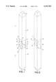
- FIG. 1 is a perspective view of a first embodiment of a contact pin
- FIG. 2 is a perspective view of a second embodiment of the contact pin
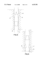
- FIGS. 3 and 4 show a partial section through a connector body which illustrates the method of operation of the invention
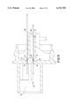
- FIG. 5 shows a section through a male strip connector as an example of a connector element according to the invention.
- the contact pin shown in FIG. 1 and having a square cross-section has two halves, 1, 1', each having a tip 2, 2' in the shape of a truncated pyramid, a stem section 3, 3' having an essentially constant cross-section in the longitudinal direction of the pin, and a wing section 4, 4' having a pair of wings 5, 5' situated opposite one another.
- the wings 5 are oriented in the opposite direction to the wings 5'.
- the essentially trapezoidal top faces 6, 6' of the wings 5, 5' merge at their broad side with a surface of the plug-in section 1 and 1', respectively.
- the narrow side of the trapezium is respectively adjoined by a retaining face 7, 7', which is oriented essentially perpendicularly to the longitudinal axis L.
- the retaining wings projecting beyond the surface of the stem sections 3, 3' have been formed by material displaced, for example by an embossing tool, from the volume illustrated by dashed lines at 9. Lying between the mutually facing retaining faces 7, 7' is a section 8 whose cross-section corresponds to that of the stem sections 3, 3' and whose length can be defined depending on the length of the chamber of the connector body in which the pin is to be mounted.
- FIG. 2 shows a second embodiment of the contact pin according to the invention.
- This contact pin differs from that shown in FIG. 1 by virtue of the fact that the retaining faces 7, 7' of the pairs of wings 5, 5' are remote from one another.
- this second embodiment affords greater protection against lateral tilting of the pins.
- a higher loadability in the direction of the pin axis can be achieved with the first embodiment since in this embodiment the retaining faces come to lie nearer to the center of the chamber 10 of the connector body.
- FIGS. 3 and 4 in each case show a side view of the middle region of a contact pin according to the second embodiment.
- the pin shown in FIG. 3 has been plugged into the chamber 10 from the top.
- the cross-section of the stem section 3 is somewhat smaller than that of the chamber 10, with the result that a small clearance 11 exists between the wall of the chamber and the pin.
- FIG. 4 shows the same pin turned through 90°. It is evident that the retaining faces 7' have pushed material in front of themselves during the press-fitting operation. The clearance 1 has largely disappeared at these sides of the pin; instead the displaced, compressed material 13 presses both against the retaining faces 7' and against the walls of the pin and, as a result, further reinforces the anchoring of the pin.
- FIG. 5 shows a male strip connector having contact pins according to the invention.
- the male strip connector has a plugging side 15 for plugging together with a female strip connector (not shown) and has chambers 10 which are provided with entry chamfers 16 and serve to receive the contact pins.
- the latter are press-fitted in the direction of the arrow 17, the pair of wings 5' oriented counter to the press-fitting direction 17 being oriented transversely with respect to the longitudinal direction of the male strip connector.
- the wings 5, 5' are preferably arranged, in the press-fitting direction, in the center of the chamber 10 or before that.
- the pins In order to complete the male strip connector shown, the pins must still be bent away at right angles, following the contour of the male strip connector, in the regions designated by 18, as a result of which they are additionally protected against being drawn out.
Abstract
Description
Claims (7)
Applications Claiming Priority (2)
| Application Number | Priority Date | Filing Date | Title |
|---|---|---|---|
| DE29700452U DE29700452U1 (en) | 1997-01-13 | 1997-01-13 | Contact pin with opposite anchoring wings and connector element |
| DE29700452U | 1997-01-13 |
Publications (1)
| Publication Number | Publication Date |
|---|---|
| US6152782A true US6152782A (en) | 2000-11-28 |
Family
ID=8034457
Family Applications (1)
| Application Number | Title | Priority Date | Filing Date |
|---|---|---|---|
| US09/006,110 Expired - Fee Related US6152782A (en) | 1997-01-13 | 1998-01-13 | Contact pin having anchoring wings in opposite directions, and connector elements |
Country Status (4)
| Country | Link |
|---|---|
| US (1) | US6152782A (en) |
| EP (1) | EP0854542B1 (en) |
| DE (2) | DE29700452U1 (en) |
| ES (1) | ES2296302T3 (en) |
Cited By (25)
| Publication number | Priority date | Publication date | Assignee | Title |
|---|---|---|---|---|
| US6328576B1 (en) * | 1999-02-19 | 2001-12-11 | Yazaki Corporation | Substrate-use terminal structure using rectangular rod |
| US20030216080A1 (en) * | 2002-05-18 | 2003-11-20 | Hans-Michael Schmitt | Conductive adhesive bond |
| US20040180584A1 (en) * | 2003-03-14 | 2004-09-16 | Klein David Allen | Pin retention apparatus, methods and articles of manufacture |
| US20040203293A1 (en) * | 2003-04-11 | 2004-10-14 | Snower Hu | Electrical contact with symmetric support means |
| US20040219841A1 (en) * | 2003-02-06 | 2004-11-04 | Sumitomo Wiring Systems, Ltd. | Connector and a terminal fitting |
| US20050159038A1 (en) * | 2004-01-16 | 2005-07-21 | Sumitomo Wiring Systems, Ltd. | Terminal fitting and a connector |
| US20050277341A1 (en) * | 2004-06-09 | 2005-12-15 | Yukio Noguchi | Terminal press-fitting structure |
| US20080032536A1 (en) * | 2006-08-04 | 2008-02-07 | Erni-Elektro-Apparate Gmbh | Plug-in connector |
| US20080124980A1 (en) * | 2006-11-23 | 2008-05-29 | Erni Electronics Gmbh | Plug-in-connector |
| US20090142967A1 (en) * | 2007-11-29 | 2009-06-04 | Yoshinori Watanabe | Contact Member, Holding Structure of Contact Member and Electrical Connector |
| US20120297852A1 (en) * | 2010-02-03 | 2012-11-29 | Yazaki Corporation | Method for manufacturing terminals having press-fit engaging parts |
| CN102891384A (en) * | 2011-07-22 | 2013-01-23 | 李尔公司 | Electrical connector |
| US20140154930A1 (en) * | 2012-12-05 | 2014-06-05 | E.G.O. Elektro-Geraetebau Gmbh | Apparatuses and methods for a plug connector |
| US20160020544A1 (en) * | 2014-07-16 | 2016-01-21 | Yazaki Corporation | Connector |
| US9455503B2 (en) | 2012-02-07 | 2016-09-27 | 3M Innovative Properties Company | Electrical connector contact terminal |
| US9509094B2 (en) | 2012-02-07 | 2016-11-29 | 3M Innovative Properties Company | Board mount electrical connector with latch opening on bottom wall |
| US9509089B2 (en) | 2012-02-07 | 2016-11-29 | 3M Innovative Properties Company | Electrical connector latch |
| US9537278B2 (en) * | 2015-02-09 | 2017-01-03 | Yazaki Corporation | Terminal group and connector |
| US9553401B2 (en) | 2012-02-07 | 2017-01-24 | 3M Innovative Properties Company | Electrical connector for strain relief for an electrical cable |
| US20180013225A1 (en) * | 2016-07-06 | 2018-01-11 | Tyco Electronics (Shanghai) Co. Ltd. | Connection Terminal and Electrical Connector |
| US9948026B2 (en) | 2012-02-07 | 2018-04-17 | 3M Innovative Properties Company | Wire mount electrical connector |
| US10236603B2 (en) * | 2015-04-22 | 2019-03-19 | Sumitomo Wiring Systems, Ltd. | Press-fit terminal |
| JP2021002475A (en) * | 2019-06-21 | 2021-01-07 | 日本圧着端子製造株式会社 | connector |
| US20220021144A1 (en) * | 2020-07-20 | 2022-01-20 | Tyco Electronics (Shanghai) Co. Ltd. | Conductive Terminal |
| US11264741B2 (en) * | 2018-02-14 | 2022-03-01 | Sumitomo Wiring Systems, Ltd. | Press-fit terminal |
Families Citing this family (2)
| Publication number | Priority date | Publication date | Assignee | Title |
|---|---|---|---|---|
| JP2004164932A (en) * | 2002-11-11 | 2004-06-10 | Sumitomo Wiring Syst Ltd | Connector |
| DE102017111293A1 (en) * | 2017-05-23 | 2018-11-29 | Te Connectivity Germany Gmbh | pin |
Citations (5)
| Publication number | Priority date | Publication date | Assignee | Title |
|---|---|---|---|---|
| DE647986C (en) * | 1936-03-01 | 1937-07-17 | Jacob Horn | Device for round grinding of pearls |
| US4707050A (en) * | 1983-01-28 | 1987-11-17 | Grote & Hartmann Gmbh & Co. Kg | Extra locking element for round plugs |
| US5035656A (en) * | 1990-05-15 | 1991-07-30 | E. I. Du Pont De Nemours And Company | Connector, circuit board contact element and retention portion |
| US5064389A (en) * | 1991-06-19 | 1991-11-12 | Amp Incorporated | Electrical slave connector |
| US5147227A (en) * | 1991-10-17 | 1992-09-15 | Amp Incorporated | Terminal retention device |
Family Cites Families (1)
| Publication number | Priority date | Publication date | Assignee | Title |
|---|---|---|---|---|
| DE9314676U1 (en) * | 1993-09-28 | 1994-02-24 | Siemens Ag | Contact pin for plug connections |
-
1997
- 1997-01-13 DE DE29700452U patent/DE29700452U1/en not_active Expired - Lifetime
- 1997-12-09 DE DE69738308T patent/DE69738308T2/en not_active Expired - Lifetime
- 1997-12-09 ES ES97121662T patent/ES2296302T3/en not_active Expired - Lifetime
- 1997-12-09 EP EP97121662A patent/EP0854542B1/en not_active Expired - Lifetime
-
1998
- 1998-01-13 US US09/006,110 patent/US6152782A/en not_active Expired - Fee Related
Patent Citations (5)
| Publication number | Priority date | Publication date | Assignee | Title |
|---|---|---|---|---|
| DE647986C (en) * | 1936-03-01 | 1937-07-17 | Jacob Horn | Device for round grinding of pearls |
| US4707050A (en) * | 1983-01-28 | 1987-11-17 | Grote & Hartmann Gmbh & Co. Kg | Extra locking element for round plugs |
| US5035656A (en) * | 1990-05-15 | 1991-07-30 | E. I. Du Pont De Nemours And Company | Connector, circuit board contact element and retention portion |
| US5064389A (en) * | 1991-06-19 | 1991-11-12 | Amp Incorporated | Electrical slave connector |
| US5147227A (en) * | 1991-10-17 | 1992-09-15 | Amp Incorporated | Terminal retention device |
Cited By (45)
| Publication number | Priority date | Publication date | Assignee | Title |
|---|---|---|---|---|
| US6328576B1 (en) * | 1999-02-19 | 2001-12-11 | Yazaki Corporation | Substrate-use terminal structure using rectangular rod |
| US7416420B2 (en) * | 2002-05-18 | 2008-08-26 | Preh-Werke Gmbh & Co. Kg | Conductive adhesive bond |
| US20030216080A1 (en) * | 2002-05-18 | 2003-11-20 | Hans-Michael Schmitt | Conductive adhesive bond |
| US20040219841A1 (en) * | 2003-02-06 | 2004-11-04 | Sumitomo Wiring Systems, Ltd. | Connector and a terminal fitting |
| US20040180584A1 (en) * | 2003-03-14 | 2004-09-16 | Klein David Allen | Pin retention apparatus, methods and articles of manufacture |
| US6896559B2 (en) * | 2003-03-14 | 2005-05-24 | Tyco Electronics Corporation | Pin retention apparatus, methods and articles of manufacture |
| US20040203293A1 (en) * | 2003-04-11 | 2004-10-14 | Snower Hu | Electrical contact with symmetric support means |
| US7175480B2 (en) * | 2003-06-02 | 2007-02-13 | Sumitomo Wiring Systems, Ltd. | Connector and a terminal fitting |
| US20050159038A1 (en) * | 2004-01-16 | 2005-07-21 | Sumitomo Wiring Systems, Ltd. | Terminal fitting and a connector |
| US7033229B2 (en) * | 2004-01-16 | 2006-04-25 | Sumitomo Wiring Systems, Ltd. | Terminal fitting and a connector |
| US20050277341A1 (en) * | 2004-06-09 | 2005-12-15 | Yukio Noguchi | Terminal press-fitting structure |
| US20080032536A1 (en) * | 2006-08-04 | 2008-02-07 | Erni-Elektro-Apparate Gmbh | Plug-in connector |
| US7591691B2 (en) * | 2006-08-04 | 2009-09-22 | Erni Electronics Gmbh | Plug-in connector |
| US20080124980A1 (en) * | 2006-11-23 | 2008-05-29 | Erni Electronics Gmbh | Plug-in-connector |
| US7448918B2 (en) * | 2006-11-23 | 2008-11-11 | Erni Electronics Gmbh | Plug-in-connector |
| US20090142967A1 (en) * | 2007-11-29 | 2009-06-04 | Yoshinori Watanabe | Contact Member, Holding Structure of Contact Member and Electrical Connector |
| US7775832B2 (en) * | 2007-11-29 | 2010-08-17 | Tyco Electronics Japan G.K. | Holding structure of a contact member for an electrical connector |
| US20120297852A1 (en) * | 2010-02-03 | 2012-11-29 | Yazaki Corporation | Method for manufacturing terminals having press-fit engaging parts |
| EP2533378A1 (en) * | 2010-02-03 | 2012-12-12 | Yazaki Corporation | Method of manufacturing terminal with press-fit engaging section |
| EP2533378A4 (en) * | 2010-02-03 | 2014-07-23 | Yazaki Corp | Method of manufacturing terminal with press-fit engaging section |
| US8951066B2 (en) | 2011-07-22 | 2015-02-10 | Lear Corporation | Electrical connector |
| CN102891384A (en) * | 2011-07-22 | 2013-01-23 | 李尔公司 | Electrical connector |
| US9553401B2 (en) | 2012-02-07 | 2017-01-24 | 3M Innovative Properties Company | Electrical connector for strain relief for an electrical cable |
| US10063006B2 (en) | 2012-02-07 | 2018-08-28 | 3M Innovative Properties Company | Wire mount electrical connector |
| US9948026B2 (en) | 2012-02-07 | 2018-04-17 | 3M Innovative Properties Company | Wire mount electrical connector |
| US9876285B2 (en) | 2012-02-07 | 2018-01-23 | 3M Innovative Properties Company | Electrical connector contact terminal |
| US9455503B2 (en) | 2012-02-07 | 2016-09-27 | 3M Innovative Properties Company | Electrical connector contact terminal |
| US9509094B2 (en) | 2012-02-07 | 2016-11-29 | 3M Innovative Properties Company | Board mount electrical connector with latch opening on bottom wall |
| US9509089B2 (en) | 2012-02-07 | 2016-11-29 | 3M Innovative Properties Company | Electrical connector latch |
| US10290954B2 (en) | 2012-02-07 | 2019-05-14 | 3M Innovative Properties Company | Electrical connector contact terminal |
| US9728864B2 (en) | 2012-02-07 | 2017-08-08 | 3M Innovative Properties Company | Electrical connector contact terminal |
| US20140154930A1 (en) * | 2012-12-05 | 2014-06-05 | E.G.O. Elektro-Geraetebau Gmbh | Apparatuses and methods for a plug connector |
| US9437951B2 (en) | 2012-12-05 | 2016-09-06 | E.G.O. Elektro-Geraetebau Gmbh | Apparatuses and methods for a plug connector |
| US9196990B2 (en) * | 2012-12-05 | 2015-11-24 | E.G.O. Elektro-Geraetebau Gmbh | Apparatuses and methods for a plug connector |
| US9515407B2 (en) * | 2014-07-16 | 2016-12-06 | Yazaki Corporation | Electrical connector with press-fitted rectangular wire terminal |
| US20160020544A1 (en) * | 2014-07-16 | 2016-01-21 | Yazaki Corporation | Connector |
| US9537278B2 (en) * | 2015-02-09 | 2017-01-03 | Yazaki Corporation | Terminal group and connector |
| US10236603B2 (en) * | 2015-04-22 | 2019-03-19 | Sumitomo Wiring Systems, Ltd. | Press-fit terminal |
| US20180013225A1 (en) * | 2016-07-06 | 2018-01-11 | Tyco Electronics (Shanghai) Co. Ltd. | Connection Terminal and Electrical Connector |
| US10680375B2 (en) * | 2016-07-06 | 2020-06-09 | Tyco Electronics (Shanghai) Co. Ltd. | Connection terminal and electrical connector |
| US11264741B2 (en) * | 2018-02-14 | 2022-03-01 | Sumitomo Wiring Systems, Ltd. | Press-fit terminal |
| JP2021002475A (en) * | 2019-06-21 | 2021-01-07 | 日本圧着端子製造株式会社 | connector |
| JP7191380B2 (en) | 2019-06-21 | 2022-12-19 | 日本圧着端子製造株式会社 | connector |
| US20220021144A1 (en) * | 2020-07-20 | 2022-01-20 | Tyco Electronics (Shanghai) Co. Ltd. | Conductive Terminal |
| US11764507B2 (en) * | 2020-07-20 | 2023-09-19 | Tyco Electronics (Shangahi) Co., Ltd. | Conductive terminal for electronic circuit board including pressing and support structures |
Also Published As
| Publication number | Publication date |
|---|---|
| DE69738308D1 (en) | 2008-01-03 |
| DE29700452U1 (en) | 1997-02-27 |
| EP0854542B1 (en) | 2007-11-21 |
| EP0854542A3 (en) | 1999-10-13 |
| DE69738308T2 (en) | 2008-10-02 |
| EP0854542A2 (en) | 1998-07-22 |
| ES2296302T3 (en) | 2008-04-16 |
Similar Documents
| Publication | Publication Date | Title |
|---|---|---|
| US6152782A (en) | Contact pin having anchoring wings in opposite directions, and connector elements | |
| US20180351275A1 (en) | Terminal fitting | |
| EP0333837B1 (en) | Connector with compressible insulative body | |
| JP3724610B2 (en) | Terminal bracket cover | |
| US4591230A (en) | Electrical connector receptacle | |
| US20020123275A1 (en) | Electrical terminal socket assembly including 90 angled and sealed connectors | |
| US6729904B2 (en) | Terminal fitting and a connector provided therewith | |
| EP1035616B1 (en) | Flexible printed circuit board crimp terminal and crimping structure for core therewith | |
| EP2157669A1 (en) | A connector and assembling method therefor | |
| CN108376870B (en) | Water-proof connector | |
| EP0845835B1 (en) | Pressure contact terminal fitting | |
| EP1294056B1 (en) | Terminal fitting, connector provided therewith and method for producing the terminal fitting | |
| US6796837B2 (en) | Connector with lock piece that longitudinally deforms | |
| EP1369963B1 (en) | A connector and a method for inserting a terminal fitting thereinto | |
| EP1376768B1 (en) | An electrical connector | |
| US6247966B1 (en) | Electrical connector with exposed molded latches | |
| US4983130A (en) | Insulation displacement contact | |
| US5487686A (en) | Pin terminal | |
| JP3561464B2 (en) | Male contact | |
| EP0991143A2 (en) | Electrical connector with contact element | |
| US6332814B2 (en) | Crimp connector with uniform bending die | |
| JP4374288B2 (en) | Wire pressure welding type connector | |
| US6155885A (en) | Terminal press-fitting construction in connector housing | |
| EP0600402B1 (en) | Electrical connector with improved terminal retention | |
| US5989076A (en) | Molded-in connector |
Legal Events
| Date | Code | Title | Description |
|---|---|---|---|
| AS | Assignment |
Owner name: FRAMATOME CONNECTORS INTERNATIONAL, FRANCE Free format text: ASSIGNMENT OF ASSIGNORS INTEREST;ASSIGNORS:VOLKERT, PETER;KOBMANN, WILLI;MAY, GUNTRAM;REEL/FRAME:009260/0349;SIGNING DATES FROM 19980515 TO 19980527 |
|
| FPAY | Fee payment |
Year of fee payment: 4 |
|
| FPAY | Fee payment |
Year of fee payment: 8 |
|
| AS | Assignment |
Owner name: FCI AUTOMOTIVE HOLDING, FRANCE Free format text: ASSIGNMENT OF ASSIGNORS INTEREST;ASSIGNOR:FCI;REEL/FRAME:026307/0310 Effective date: 20110407 |
|
| REMI | Maintenance fee reminder mailed | ||
| LAPS | Lapse for failure to pay maintenance fees | ||
| STCH | Information on status: patent discontinuation |
Free format text: PATENT EXPIRED DUE TO NONPAYMENT OF MAINTENANCE FEES UNDER 37 CFR 1.362 |
|
| FP | Lapsed due to failure to pay maintenance fee |
Effective date: 20121128 |