US6152759A - Strain relief mechanism for an insulation displacement connector - Google Patents
Strain relief mechanism for an insulation displacement connector Download PDFInfo
- Publication number
- US6152759A US6152759A US09/217,772 US21777298A US6152759A US 6152759 A US6152759 A US 6152759A US 21777298 A US21777298 A US 21777298A US 6152759 A US6152759 A US 6152759A
- Authority
- US
- United States
- Prior art keywords
- wire
- connector
- strain relief
- cap section
- cap
- Prior art date
- Legal status (The legal status is an assumption and is not a legal conclusion. Google has not performed a legal analysis and makes no representation as to the accuracy of the status listed.)
- Expired - Lifetime
Links
- 238000009413 insulation Methods 0.000 title claims abstract description 19
- 238000006073 displacement reaction Methods 0.000 title claims abstract description 17
- 238000003780 insertion Methods 0.000 claims abstract description 37
- 230000037431 insertion Effects 0.000 claims abstract description 37
- 230000000717 retained effect Effects 0.000 claims abstract description 6
- 238000004891 communication Methods 0.000 claims abstract description 4
- 239000012530 fluid Substances 0.000 claims abstract description 4
- 238000005452 bending Methods 0.000 claims description 6
- 230000001012 protector Effects 0.000 description 5
- 239000004020 conductor Substances 0.000 description 2
- 238000013461 design Methods 0.000 description 2
- 238000000034 method Methods 0.000 description 2
- 238000012360 testing method Methods 0.000 description 2
- 230000000694 effects Effects 0.000 description 1
- 238000005516 engineering process Methods 0.000 description 1
- 231100001261 hazardous Toxicity 0.000 description 1
- 230000014759 maintenance of location Effects 0.000 description 1
- 239000000463 material Substances 0.000 description 1
- 230000013011 mating Effects 0.000 description 1
- 238000006467 substitution reaction Methods 0.000 description 1
Images
Classifications
-
- H—ELECTRICITY
- H01—ELECTRIC ELEMENTS
- H01R—ELECTRICALLY-CONDUCTIVE CONNECTIONS; STRUCTURAL ASSOCIATIONS OF A PLURALITY OF MUTUALLY-INSULATED ELECTRICAL CONNECTING ELEMENTS; COUPLING DEVICES; CURRENT COLLECTORS
- H01R13/00—Details of coupling devices of the kinds covered by groups H01R12/70 or H01R24/00 - H01R33/00
- H01R13/58—Means for relieving strain on wire connection, e.g. cord grip, for avoiding loosening of connections between wires and terminals within a coupling device terminating a cable
- H01R13/582—Means for relieving strain on wire connection, e.g. cord grip, for avoiding loosening of connections between wires and terminals within a coupling device terminating a cable the cable being clamped between assembled parts of the housing
- H01R13/5829—Means for relieving strain on wire connection, e.g. cord grip, for avoiding loosening of connections between wires and terminals within a coupling device terminating a cable the cable being clamped between assembled parts of the housing the clamping part being flexibly or hingedly connected to the housing
-
- H—ELECTRICITY
- H01—ELECTRIC ELEMENTS
- H01R—ELECTRICALLY-CONDUCTIVE CONNECTIONS; STRUCTURAL ASSOCIATIONS OF A PLURALITY OF MUTUALLY-INSULATED ELECTRICAL CONNECTING ELEMENTS; COUPLING DEVICES; CURRENT COLLECTORS
- H01R4/00—Electrically-conductive connections between two or more conductive members in direct contact, i.e. touching one another; Means for effecting or maintaining such contact; Electrically-conductive connections having two or more spaced connecting locations for conductors and using contact members penetrating insulation
- H01R4/24—Connections using contact members penetrating or cutting insulation or cable strands
- H01R4/2416—Connections using contact members penetrating or cutting insulation or cable strands the contact members having insulation-cutting edges, e.g. of tuning fork type
- H01R4/242—Connections using contact members penetrating or cutting insulation or cable strands the contact members having insulation-cutting edges, e.g. of tuning fork type the contact members being plates having a single slot
- H01R4/2425—Flat plates, e.g. multi-layered flat plates
- H01R4/2429—Flat plates, e.g. multi-layered flat plates mounted in an insulating base
- H01R4/2433—Flat plates, e.g. multi-layered flat plates mounted in an insulating base one part of the base being movable to push the cable into the slot
Definitions
- This invention relates generally to the field of telephone wire connectors and distribution systems, and specifically to a strain relief mechanism for an insulation displacement connector (IDC).
- IDC insulation displacement connector
- Telephone lines which are carried by electrical conductors known as tip ring wire pairs, are generally aggregated at a particular point in a building prior to being distributed and connected to various types of telephone equipment, such as, for example, telephones, fax machines, modems etc.
- the individual tip ring wire pairs must first be broken out from the cable into individual wire pairs. This is normally accomplished in a junction box known as, for example, a building entrance protector (BEP), or network interface unit (NIU).
- BEP building entrance protector
- NNU network interface unit
- protector device inserted between the telephone and central office, or network side of the telephone line and the customer equipment or terminal side of the telephone line to protect the telephone and user, or other equipment connected to the telephone line, from hazardous overvoltages induced in the telephone network or in the cables passing between the telephone central office and the building within which the line is terminated.
- the telephone lines coming from the network are first wired to a protector field, which is an array of connectors for receiving the protector device, which is in turn hard wired to a first connector block which provides a first test point for testing the telephone line connections between the building and telephone central office.
- This first terminal block is hard wired to a multi pair connector, most typically a twenty-five pair connector of the RJ21 type, for further connection to an array of customer bridges which are also hard wired and connectorized via a mating RJ21 connector.
- the use of a customer bridge permits a subscriber to disconnect terminal equipment from a telephone line so that the subscriber can isolate troubles on the line as originating in the telephone network, or on the terminal equipment side of the telephone line.
- insulation displacement connector (IDC) blocks for use in such junction boxes and/or distribution fields, such as the ubiquitous punch down connector block, also known as a 66-type connector block, and the tool-less insulation displacement connector blocks utilizing push cap connectors, such as that described in U.S. Pat. No. 4,913,659 dated Apr. 3, 1990, the entire disclosure of which is incorporated herein by reference.
- a connector block is commercially available under the product designation SC99 from Lucent Technologies Inc.
- SC99 product designation
- Other connectors used for telephony wiring applications are described in U.S. Pat. No. 4,662,699 to Vachhani et al., dated May 5, 1987, and in U.S. Pat. No. 3,611,264 to Ellis, dated Oct. 5, 1971.
- Mini-Rocker Connectors such as those sold by A. C. Egerton Ltd., which hold a tip-ring wire pair in terminals retained under a single movable cap through which both wires of the pair are inserted.
- a strain relief mechanism for an insulation displacement connector comprises a cap section and a base section.
- the base section is connected to the cap section at a pivot point.
- the cap section has at least one wire insertion channel and a first wall.
- the wire insertion channel has an entrance aperture which is in fluid communication with an exit aperture for passage therethrough in an insertion direction of an inserted wire.
- the exit aperture is contained in the first wall.
- the cap section is pivotally moveable between an open position which facilitates insertion of the wire into the cap section through the entrance aperture and out through the exit aperture, and a closed position.
- the base section has a side wall and a base hole or depression formed in the base section at the foot of the side wall.
- the base hole includes a wire stop portion at its bottom.
- the base hole is disposed such that passage of the inserted wire out through the exit aperture into the open portion of the base hole is limited by abutment against the wire stop portion at the bottom of the base hole.
- the wire is retained in the base hole at a first orientation which is substantially parallel to the insertion direction of the inserted wire.
- the first wall of the cap section forces the wire into contact with the side wall so as to cause the wire to be bent and thus oriented at a wire bend angle in a second orientation. In this second orientation, the wire is restrained in the connector as a result of this forced bend and thereby is strain relieved.
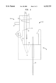
- FIG. 1 is a side elevational view of a connector constructed in accordance with a preferred embodiment of the present invention with the cap section in the open position;
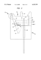
- FIG. 2 is a side elevational view of the connector of FIG. 1 with the cap section in the closed position;
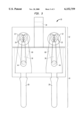
- FIG. 3 is a front elevational view of the connector of FIG. 1 with the cap section in the closed position.
- FIGS. 1-2 illustrate an insulation displacement connector of the present invention, generally indicated as 10.
- Connector 10 has a cap section, generally indicated as 12, and a base section, generally indicated as 14.
- Cap section 12 is connected to base section 14 at a preferably hinged pivot point 32.
- Cap section 12 pivots about pivot point 32 and is moveable between an open position, as illustrated in FIG. 1, and a closed position, as illustrated in FIG. 2.
- Base section 14 is preferably fixed to, for example, a connector block (not shown) or other mounting surface and includes at least one terminal strip 28.
- Cap section 12 of connector 10 has at least one wire insertion channel 20.
- cap section 12 of connector 10 comprises two wire insertion channels 20, one for each wire of a tip-ring wire pair. Although the discussion here will focus on one wire insertion channel, cap section 12 of connector 10 may contain a plurality of wire insertion channels 20.
- FIG. 3 illustrates a front elevational view of the connector of FIGS. 1-2, and shows that cap section 12 of connector 10 has two wire insertion channels 20.
- Each wire insertion channel 20 includes an entrance aperture 22 and an exit aperture 23. Entrance aperture 22 is in fluid communication with exit aperture 23. Exit aperture 23 is disposed on a first wall 25 of cap section 12. Entrance aperture 22 and exit aperture 23 allow for the passage, in an insertion direction I, of an inserted wire 30 through wire insertion channel 20 and beyond.
- Base section 14 includes a base hole 60 and a side wall 59.
- Base hole 60 includes a wire stop portion 44.
- Base hole 60 is disposed such that with cap section 12 in the open position, passage of wire 30 from exit aperture 23 guides wire 30 along side wall 59 into base hole 60. Entry of wire 30 into base hole 60 is limited by the abutment of wire 30 against wire stop portion 44.
- wire 30 is retained in base hole 60 at a first orientation which is substantially parallel to the direction of wire insertion discussed above.
- Base hole 60 is preferably tapered as shown so as to facilitate the bending of wire 30 at a predetermined bend angle discussed below. The designer of ordinary skill will, however, recognize that hole 60 can be formed of numerous shapes and sizes to meet application design-specific needs.
- Cap section 12 of connector 10 also includes terminal strip receiving portions 26, which are constructed so as to be capable of receiving therein terminal strips 28 when cap section 12 is in the closed position, as illustrated in FIG. 2.
- terminal strip receiving portions 26 When cap section 12 of connector 10 is in the open position, terminal strips 28 are not housed in terminal strip receiving portions 26 and do not intersect wire insertion channel 20. However, when cap section 12 is in the closed position, as illustrated in FIGS. 2-3, terminal strips 28 are housed in terminal strip receiving portions 26 and intersect wire insertion channel 20.
- wire 30 is generally passed through cap section 12 by inserting it in the insertion direction I (FIG. 1) into entrance aperture 22 and causing it to exit cap section 12 through exit aperture 23.
- exit aperture 23 substantially overlies base hole 60 of base section 14.
- Wire 30 passing through entrance aperture 22 and exit aperture 23 can be guidedly received in base hole 60 by slidable, guided movement along side wall 59.
- Wire 30 can travel down side wall 59 into base hole 60 until it abuts against wire stop portion 44.
- wire 30 is positioned in base hole 60 at a first orientation as illustrated in FIG. 1.
- a slight bend occurs in wire 30 as it slides down side wall 59, as shown in FIG. 1. This facilitates bending of wire 30, as discussed further below.
- FIG. 2 depicts connector 10 with cap section 12 in the closed position.
- This closed position is achieved by pushing cap section 12 in a downward direction towards base section 14.
- Cap section 12 may be gripped at finger grip member 34 to facilitate the hinged pivoting movement of cap section 12.
- wire 30 is driven into contact with terminal strip 28 whereupon it is stripped of insulation and mechanically and electrically coupled with terminal strip 28 within connector 10, in a manner known in the art (FIG. 3).
- terminal strips 28 are housed in terminal strip receiving portions 26, as best seen in FIG. 2.
- cap section 12 when cap section 12 is moved from the open position as illustrated in FIG. 1 to the closed position as illustrated in FIG. 2, first wall 25 of cap section 12 forces wire 30 into contact with side wall 59 of base section 14. This results in wire 30 being bent at a wire bend angle 55, as illustrated in FIG. 2.
- the length of wire 30 contained within wire insertion channel 20 is disposed at a second orientation which is angled, at the wire bend angle 55, relative to the orientation of the length of wire 30 contained within base hole 60.
- the bending of wire 30 at bend angle 55 creates a strain relief on wire 30, resisting any pulling on wire 30 in the direction of force F, shown in FIG. 2.
- first wall 25 In the closed position, first wall 25 preferably, although not necessarily, causes wire 30 to be pushed against side wall 59 of base section 14 at a pressure zone 50.
- the pressure applied by first wall 25 on wire 30 provides additional resistance to any pulling force that may be applied to wire 30.
- resistance to any pulling force on wire 30 is provided by the length of wire 30 contained between first wall 25 and side wall 59 in pressure zone 50, and not solely by the compressive force exerted by terminal strip 28 on the portion of wire 30 gripped thereby, as in prior art connectors.
- Pressure zone 50 fields the brunt of any pulling force that may be applied to wire 30. Consequently, the wire portion retained within terminal strip 28 is relieved from any strain which may result from the application of a pulling force F on wire 30 (FIG. 2).
- this mechanism provides for strong strain relief for connector 10.
- strain relief can be exclusively provided by the bending of wire 30 at bend angle 55, as discussed above.
- Connector 10, along with cap section 12, is preferably, although not necessarily, designed in such a manner that wire 30 will break before it is released at pressure zone 50 and slides out of base hole 60, exit aperture 23, and entrance aperture 22.
- This provides for an efficient strain relief mechanism for connector 10.
- wire bend angle 55 of wire 30 is approximately equal to or less than 90°, although the person of skill will recognize that the precise angle 55, the length of wire 30 disposed in base hole 60, as well as the dimensions of wire insertion channel 20 and base hole 60, are a matter of application specific design requirements and are thus readily adaptable by the person of skill utilizing the teachings herein.
- wire bend angle 55 may be, for example, about 60° to about 120°.
- wire insertion channel 20 may be shaped and sized to provide additional retention of wire 30 through frictional engagement of wire 30 and the interior surface of wire insertion channel 20, provided that the friction introduced is not unduly high, so as to avoid the introduction of strain on wire 30 as cap section 12 of connector 10 is moved from the open position to the closed position.
- Cap section 12 and base section 14 may be formed of any art-recognized material having the proper insulating and mechanical properties. Preferably, plastic is employed.
- the strain relieving mechanism of the present invention can be applied to a variety of connectors including Network Interface Device (NID) connectors and tool less IDC connectors. NID connectors normally face a great deal of wire tracing activities. Frequently, pulling forces applied on the wire during the wire tracing process causes the tip and ring wire to be dislodged from the IDC terminal strip. Consequently, the strain relief mechanism of the present invention helps prevent such dislodgment during the wire tracing process. Further, the strain relieved connector of the present invention may be used on a connector block wherein selective or all connectors on the connector block are strain relieved. Additionally, the connector of the present invention may be used in a wiring enclosure, such as a Building Entrance Protector (BEP) or a Network Interface Unit (NIU).
- BEP Building Entrance Protector
- NU Network Interface Unit
Abstract
Description
Claims (26)
Priority Applications (1)
| Application Number | Priority Date | Filing Date | Title |
|---|---|---|---|
| US09/217,772 US6152759A (en) | 1998-12-21 | 1998-12-21 | Strain relief mechanism for an insulation displacement connector |
Applications Claiming Priority (1)
| Application Number | Priority Date | Filing Date | Title |
|---|---|---|---|
| US09/217,772 US6152759A (en) | 1998-12-21 | 1998-12-21 | Strain relief mechanism for an insulation displacement connector |
Publications (1)
| Publication Number | Publication Date |
|---|---|
| US6152759A true US6152759A (en) | 2000-11-28 |
Family
ID=22812446
Family Applications (1)
| Application Number | Title | Priority Date | Filing Date |
|---|---|---|---|
| US09/217,772 Expired - Lifetime US6152759A (en) | 1998-12-21 | 1998-12-21 | Strain relief mechanism for an insulation displacement connector |
Country Status (1)
| Country | Link |
|---|---|
| US (1) | US6152759A (en) |
Cited By (10)
| Publication number | Priority date | Publication date | Assignee | Title |
|---|---|---|---|---|
| US6500020B2 (en) | 2000-06-20 | 2002-12-31 | Corning Cable Systems Llc | Top loading customer bridge |
| KR100440051B1 (en) * | 2001-05-02 | 2004-07-14 | 대은전자 주식회사 | Splitter terminal board |
| US20050227529A1 (en) * | 2004-04-08 | 2005-10-13 | Gelcore Llc | Multi-conductor parallel splice connection |
| US20080293288A1 (en) * | 2007-05-22 | 2008-11-27 | Panduit Corp. | Raceway IDC Connector |
| WO2011051691A1 (en) * | 2009-11-02 | 2011-05-05 | Robert Edward Clark | Electrical connection box |
| EP2343782A3 (en) * | 2010-01-12 | 2012-11-07 | Yamaichi Electronics Deutschland GmbH | Fast connect interface |
| US9035184B2 (en) | 2011-11-03 | 2015-05-19 | Blazing Products, Inc. | Electrical connectors |
| US9627795B2 (en) | 2014-11-21 | 2017-04-18 | Duane K. Smith | Electrical connecting assemblies, and related methods |
| GB2586833A (en) * | 2019-09-05 | 2021-03-10 | Thelwell Robert | A connector and method for making electrical connection between a terminal and a wire |
| US11081848B2 (en) * | 2019-10-22 | 2021-08-03 | John Holtzman | Charger extension device |
Citations (5)
| Publication number | Priority date | Publication date | Assignee | Title |
|---|---|---|---|---|
| US3611264A (en) * | 1968-12-27 | 1971-10-05 | Bell Telephone Labor Inc | Wire connecting blocks |
| US4426125A (en) * | 1980-11-05 | 1984-01-17 | Amp Incorporated | Flat cable electrical connector |
| US4684195A (en) * | 1985-12-19 | 1987-08-04 | American Telephone And Telegraph Company, At&T Bell Laboratories | Solderless electrical connector |
| EP0274948A1 (en) * | 1986-12-15 | 1988-07-20 | Telemecanique | Insulation displacement connector for a monoconductor cable |
| US6045392A (en) * | 1998-06-30 | 2000-04-04 | Lucent Technologies Inc. | Modified index strip with integrated push cap for wire termination |
-
1998
- 1998-12-21 US US09/217,772 patent/US6152759A/en not_active Expired - Lifetime
Patent Citations (5)
| Publication number | Priority date | Publication date | Assignee | Title |
|---|---|---|---|---|
| US3611264A (en) * | 1968-12-27 | 1971-10-05 | Bell Telephone Labor Inc | Wire connecting blocks |
| US4426125A (en) * | 1980-11-05 | 1984-01-17 | Amp Incorporated | Flat cable electrical connector |
| US4684195A (en) * | 1985-12-19 | 1987-08-04 | American Telephone And Telegraph Company, At&T Bell Laboratories | Solderless electrical connector |
| EP0274948A1 (en) * | 1986-12-15 | 1988-07-20 | Telemecanique | Insulation displacement connector for a monoconductor cable |
| US6045392A (en) * | 1998-06-30 | 2000-04-04 | Lucent Technologies Inc. | Modified index strip with integrated push cap for wire termination |
Cited By (12)
| Publication number | Priority date | Publication date | Assignee | Title |
|---|---|---|---|---|
| US6500020B2 (en) | 2000-06-20 | 2002-12-31 | Corning Cable Systems Llc | Top loading customer bridge |
| KR100440051B1 (en) * | 2001-05-02 | 2004-07-14 | 대은전자 주식회사 | Splitter terminal board |
| US20050227529A1 (en) * | 2004-04-08 | 2005-10-13 | Gelcore Llc | Multi-conductor parallel splice connection |
| US20080293288A1 (en) * | 2007-05-22 | 2008-11-27 | Panduit Corp. | Raceway IDC Connector |
| US7530827B2 (en) | 2007-05-22 | 2009-05-12 | Penduit Corp. | Raceway IDC connector |
| WO2011051691A1 (en) * | 2009-11-02 | 2011-05-05 | Robert Edward Clark | Electrical connection box |
| EP2343782A3 (en) * | 2010-01-12 | 2012-11-07 | Yamaichi Electronics Deutschland GmbH | Fast connect interface |
| US9035184B2 (en) | 2011-11-03 | 2015-05-19 | Blazing Products, Inc. | Electrical connectors |
| US9614297B2 (en) | 2011-11-03 | 2017-04-04 | Blazing Products, Inc. | Electrical connectors |
| US9627795B2 (en) | 2014-11-21 | 2017-04-18 | Duane K. Smith | Electrical connecting assemblies, and related methods |
| GB2586833A (en) * | 2019-09-05 | 2021-03-10 | Thelwell Robert | A connector and method for making electrical connection between a terminal and a wire |
| US11081848B2 (en) * | 2019-10-22 | 2021-08-03 | John Holtzman | Charger extension device |
Similar Documents
| Publication | Publication Date | Title |
|---|---|---|
| US5860829A (en) | Cross connect terminal block | |
| CA2160377C (en) | Telecommunications terminal block | |
| KR100591673B1 (en) | Outlet and connecting block and plug of telecommunications | |
| AU751272B2 (en) | Communication cable terminating plug | |
| EP0154414B1 (en) | Round cable adaptor for modular plug | |
| US5727962A (en) | Modular plug connector | |
| US6159036A (en) | Locking latch mechanism for an insulation displacement connector | |
| HUT64799A (en) | Electric connector protected against harmful electric effects | |
| US6113421A (en) | Strain relief mechanism for an insulation displacement connector | |
| US6152759A (en) | Strain relief mechanism for an insulation displacement connector | |
| US4351579A (en) | Clamp for electrical cable and cable terminating system | |
| US5004433A (en) | Interconnection device | |
| US4099819A (en) | Modular termination system for telecommunication devices | |
| US6319048B1 (en) | Crimp locked wire manager for a communication plug | |
| US6123566A (en) | Terminal strip with integrated strain relief mechanism for an insulation displacement connector | |
| EP1221184A2 (en) | Vertical and right angle modular outlets | |
| EP0122286A1 (en) | Communication plug connection tool | |
| US7097513B2 (en) | Telecommunication connector | |
| US4019801A (en) | Electrical splice | |
| US6231373B1 (en) | Connector with integrated living hinge and resettable spring | |
| US6368143B1 (en) | Modular plug with two piece housing | |
| US6056584A (en) | Dual sided insulation displacement connector block | |
| US6139352A (en) | Insulation displacement connector with selectively removable abutment wall | |
| US6283785B1 (en) | Connector top cap | |
| US5961342A (en) | Dual sided insulation displacement connector terminal strip |
Legal Events
| Date | Code | Title | Description |
|---|---|---|---|
| AS | Assignment |
Owner name: LUCENT TECHNOLOGIES INC., NEW JERSEY Free format text: ASSIGNMENT OF ASSIGNORS INTEREST;ASSIGNORS:DAOUD, BASSEL H.;HELMSTETTER, CHRISTOPHER M.;FIGUEIREDO, ANTONIO A.;AND OTHERS;REEL/FRAME:009674/0199 Effective date: 19981218 |
|
| STCF | Information on status: patent grant |
Free format text: PATENTED CASE |
|
| AS | Assignment |
Owner name: AVAYA TECHNOLOGY CORP., NEW JERSEY Free format text: ASSIGNMENT OF ASSIGNORS INTEREST;ASSIGNOR:LUCENT TECHNOLOGIES INC.;REEL/FRAME:012691/0572 Effective date: 20000929 |
|
| AS | Assignment |
Owner name: BANK OF NEW YORK, THE, NEW YORK Free format text: SECURITY INTEREST;ASSIGNOR:AVAYA TECHNOLOGY CORP.;REEL/FRAME:012762/0098 Effective date: 20020405 |
|
| FPAY | Fee payment |
Year of fee payment: 4 |
|
| AS | Assignment |
Owner name: AVAYA TECHNOLOGY CORPORATION, NEW JERSEY Free format text: RELEASE BY SECURED PARTY;ASSIGNOR:THE BANK OF NEW YORK;REEL/FRAME:019881/0532 Effective date: 20040101 |
|
| AS | Assignment |
Owner name: COMMSCOPE SOLUTIONS PROPERTIES, LLC, NEVADA Free format text: ASSIGNMENT OF ASSIGNORS INTEREST;ASSIGNOR:AVAYA TECHNOLOGY CORPORATION;REEL/FRAME:019984/0055 Effective date: 20040129 |
|
| AS | Assignment |
Owner name: COMMSCOPE, INC. OF NORTH CAROLINA, NORTH CAROLINA Free format text: MERGER;ASSIGNOR:COMMSCOPE SOLUTIONS PROPERTIES, LLC;REEL/FRAME:019991/0643 Effective date: 20061220 Owner name: COMMSCOPE, INC. OF NORTH CAROLINA,NORTH CAROLINA Free format text: MERGER;ASSIGNOR:COMMSCOPE SOLUTIONS PROPERTIES, LLC;REEL/FRAME:019991/0643 Effective date: 20061220 |
|
| AS | Assignment |
Owner name: BANK OF AMERICA, N.A., AS ADMINISTRATIVE AGENT, CA Free format text: SECURITY AGREEMENT;ASSIGNORS:COMMSCOPE, INC. OF NORTH CAROLINA;ALLEN TELECOM, LLC;ANDREW CORPORATION;REEL/FRAME:020362/0241 Effective date: 20071227 Owner name: BANK OF AMERICA, N.A., AS ADMINISTRATIVE AGENT,CAL Free format text: SECURITY AGREEMENT;ASSIGNORS:COMMSCOPE, INC. OF NORTH CAROLINA;ALLEN TELECOM, LLC;ANDREW CORPORATION;REEL/FRAME:020362/0241 Effective date: 20071227 |
|
| FPAY | Fee payment |
Year of fee payment: 8 |
|
| AS | Assignment |
Owner name: COMMSCOPE, INC. OF NORTH CAROLINA, NORTH CAROLINA Free format text: PATENT RELEASE;ASSIGNOR:BANK OF AMERICA, N.A., AS ADMINISTRATIVE AGENT;REEL/FRAME:026039/0005 Effective date: 20110114 Owner name: ALLEN TELECOM LLC, NORTH CAROLINA Free format text: PATENT RELEASE;ASSIGNOR:BANK OF AMERICA, N.A., AS ADMINISTRATIVE AGENT;REEL/FRAME:026039/0005 Effective date: 20110114 Owner name: ANDREW LLC (F/K/A ANDREW CORPORATION), NORTH CAROL Free format text: PATENT RELEASE;ASSIGNOR:BANK OF AMERICA, N.A., AS ADMINISTRATIVE AGENT;REEL/FRAME:026039/0005 Effective date: 20110114 |
|
| AS | Assignment |
Owner name: JPMORGAN CHASE BANK, N.A., AS COLLATERAL AGENT, NE Free format text: SECURITY AGREEMENT;ASSIGNORS:ALLEN TELECOM LLC, A DELAWARE LLC;ANDREW LLC, A DELAWARE LLC;COMMSCOPE, INC. OF NORTH CAROLINA, A NORTH CAROLINA CORPORATION;REEL/FRAME:026276/0363 Effective date: 20110114 |
|
| AS | Assignment |
Owner name: JPMORGAN CHASE BANK, N.A., AS COLLATERAL AGENT, NE Free format text: SECURITY AGREEMENT;ASSIGNORS:ALLEN TELECOM LLC, A DELAWARE LLC;ANDREW LLC, A DELAWARE LLC;COMMSCOPE, INC OF NORTH CAROLINA, A NORTH CAROLINA CORPORATION;REEL/FRAME:026272/0543 Effective date: 20110114 |
|
| FPAY | Fee payment |
Year of fee payment: 12 |
|
| AS | Assignment |
Owner name: WILMINGTON TRUST, NATIONAL ASSOCIATION, AS COLLATERAL AGENT, CONNECTICUT Free format text: SECURITY INTEREST;ASSIGNORS:ALLEN TELECOM LLC;COMMSCOPE TECHNOLOGIES LLC;COMMSCOPE, INC. OF NORTH CAROLINA;AND OTHERS;REEL/FRAME:036201/0283 Effective date: 20150611 Owner name: WILMINGTON TRUST, NATIONAL ASSOCIATION, AS COLLATE Free format text: SECURITY INTEREST;ASSIGNORS:ALLEN TELECOM LLC;COMMSCOPE TECHNOLOGIES LLC;COMMSCOPE, INC. OF NORTH CAROLINA;AND OTHERS;REEL/FRAME:036201/0283 Effective date: 20150611 |
|
| AS | Assignment |
Owner name: ALLEN TELECOM LLC, NORTH CAROLINA Free format text: RELEASE OF SECURITY INTEREST PATENTS (RELEASES RF 036201/0283);ASSIGNOR:WILMINGTON TRUST, NATIONAL ASSOCIATION;REEL/FRAME:042126/0434 Effective date: 20170317 Owner name: COMMSCOPE TECHNOLOGIES LLC, NORTH CAROLINA Free format text: RELEASE OF SECURITY INTEREST PATENTS (RELEASES RF 036201/0283);ASSIGNOR:WILMINGTON TRUST, NATIONAL ASSOCIATION;REEL/FRAME:042126/0434 Effective date: 20170317 Owner name: COMMSCOPE, INC. OF NORTH CAROLINA, NORTH CAROLINA Free format text: RELEASE OF SECURITY INTEREST PATENTS (RELEASES RF 036201/0283);ASSIGNOR:WILMINGTON TRUST, NATIONAL ASSOCIATION;REEL/FRAME:042126/0434 Effective date: 20170317 Owner name: REDWOOD SYSTEMS, INC., NORTH CAROLINA Free format text: RELEASE OF SECURITY INTEREST PATENTS (RELEASES RF 036201/0283);ASSIGNOR:WILMINGTON TRUST, NATIONAL ASSOCIATION;REEL/FRAME:042126/0434 Effective date: 20170317 |
|
| AS | Assignment |
Owner name: AVAYA INC. (FORMERLY KNOWN AS AVAYA TECHNOLOGY COR Free format text: BANKRUPTCY COURT ORDER RELEASING ALL LIENS INCLUDING THE SECURITY INTEREST RECORDED AT REEL/FRAME 012762/0098;ASSIGNOR:THE BANK OF NEW YORK;REEL/FRAME:044893/0001 Effective date: 20171128 |
|
| AS | Assignment |
Owner name: COMMSCOPE TECHNOLOGIES LLC, NORTH CAROLINA Free format text: RELEASE BY SECURED PARTY;ASSIGNOR:JPMORGAN CHASE BANK, N.A.;REEL/FRAME:048840/0001 Effective date: 20190404 Owner name: ALLEN TELECOM LLC, ILLINOIS Free format text: RELEASE BY SECURED PARTY;ASSIGNOR:JPMORGAN CHASE BANK, N.A.;REEL/FRAME:048840/0001 Effective date: 20190404 Owner name: COMMSCOPE, INC. OF NORTH CAROLINA, NORTH CAROLINA Free format text: RELEASE BY SECURED PARTY;ASSIGNOR:JPMORGAN CHASE BANK, N.A.;REEL/FRAME:048840/0001 Effective date: 20190404 Owner name: REDWOOD SYSTEMS, INC., NORTH CAROLINA Free format text: RELEASE BY SECURED PARTY;ASSIGNOR:JPMORGAN CHASE BANK, N.A.;REEL/FRAME:048840/0001 Effective date: 20190404 Owner name: ANDREW LLC, NORTH CAROLINA Free format text: RELEASE BY SECURED PARTY;ASSIGNOR:JPMORGAN CHASE BANK, N.A.;REEL/FRAME:048840/0001 Effective date: 20190404 Owner name: COMMSCOPE, INC. OF NORTH CAROLINA, NORTH CAROLINA Free format text: RELEASE BY SECURED PARTY;ASSIGNOR:JPMORGAN CHASE BANK, N.A.;REEL/FRAME:049260/0001 Effective date: 20190404 Owner name: ALLEN TELECOM LLC, ILLINOIS Free format text: RELEASE BY SECURED PARTY;ASSIGNOR:JPMORGAN CHASE BANK, N.A.;REEL/FRAME:049260/0001 Effective date: 20190404 Owner name: ANDREW LLC, NORTH CAROLINA Free format text: RELEASE BY SECURED PARTY;ASSIGNOR:JPMORGAN CHASE BANK, N.A.;REEL/FRAME:049260/0001 Effective date: 20190404 Owner name: REDWOOD SYSTEMS, INC., NORTH CAROLINA Free format text: RELEASE BY SECURED PARTY;ASSIGNOR:JPMORGAN CHASE BANK, N.A.;REEL/FRAME:049260/0001 Effective date: 20190404 Owner name: COMMSCOPE TECHNOLOGIES LLC, NORTH CAROLINA Free format text: RELEASE BY SECURED PARTY;ASSIGNOR:JPMORGAN CHASE BANK, N.A.;REEL/FRAME:049260/0001 Effective date: 20190404 |