US6152638A - Extendable legs for stands or similar appliances - Google Patents
Extendable legs for stands or similar appliances Download PDFInfo
- Publication number
- US6152638A US6152638A US09/171,872 US17187299A US6152638A US 6152638 A US6152638 A US 6152638A US 17187299 A US17187299 A US 17187299A US 6152638 A US6152638 A US 6152638A
- Authority
- US
- United States
- Prior art keywords
- final
- leg
- respect
- locking device
- intermediate member
- Prior art date
- Legal status (The legal status is an assumption and is not a legal conclusion. Google has not performed a legal analysis and makes no representation as to the accuracy of the status listed.)
- Expired - Lifetime
Links
- 230000003287 optical effect Effects 0.000 description 2
Images

Classifications
-
- F—MECHANICAL ENGINEERING; LIGHTING; HEATING; WEAPONS; BLASTING
- F16—ENGINEERING ELEMENTS AND UNITS; GENERAL MEASURES FOR PRODUCING AND MAINTAINING EFFECTIVE FUNCTIONING OF MACHINES OR INSTALLATIONS; THERMAL INSULATION IN GENERAL
- F16M—FRAMES, CASINGS OR BEDS OF ENGINES, MACHINES OR APPARATUS, NOT SPECIFIC TO ENGINES, MACHINES OR APPARATUS PROVIDED FOR ELSEWHERE; STANDS; SUPPORTS
- F16M11/00—Stands or trestles as supports for apparatus or articles placed thereon ; Stands for scientific apparatus such as gravitational force meters
- F16M11/20—Undercarriages with or without wheels
- F16M11/24—Undercarriages with or without wheels changeable in height or length of legs, also for transport only, e.g. by means of tubes screwed into each other
- F16M11/26—Undercarriages with or without wheels changeable in height or length of legs, also for transport only, e.g. by means of tubes screwed into each other by telescoping, with or without folding
- F16M11/28—Undercarriages for supports with one single telescoping pillar
-
- F—MECHANICAL ENGINEERING; LIGHTING; HEATING; WEAPONS; BLASTING
- F16—ENGINEERING ELEMENTS AND UNITS; GENERAL MEASURES FOR PRODUCING AND MAINTAINING EFFECTIVE FUNCTIONING OF MACHINES OR INSTALLATIONS; THERMAL INSULATION IN GENERAL
- F16M—FRAMES, CASINGS OR BEDS OF ENGINES, MACHINES OR APPARATUS, NOT SPECIFIC TO ENGINES, MACHINES OR APPARATUS PROVIDED FOR ELSEWHERE; STANDS; SUPPORTS
- F16M11/00—Stands or trestles as supports for apparatus or articles placed thereon ; Stands for scientific apparatus such as gravitational force meters
- F16M11/20—Undercarriages with or without wheels
- F16M11/24—Undercarriages with or without wheels changeable in height or length of legs, also for transport only, e.g. by means of tubes screwed into each other
- F16M11/26—Undercarriages with or without wheels changeable in height or length of legs, also for transport only, e.g. by means of tubes screwed into each other by telescoping, with or without folding
- F16M11/32—Undercarriages for supports with three or more telescoping legs
-
- F—MECHANICAL ENGINEERING; LIGHTING; HEATING; WEAPONS; BLASTING
- F16—ENGINEERING ELEMENTS AND UNITS; GENERAL MEASURES FOR PRODUCING AND MAINTAINING EFFECTIVE FUNCTIONING OF MACHINES OR INSTALLATIONS; THERMAL INSULATION IN GENERAL
- F16M—FRAMES, CASINGS OR BEDS OF ENGINES, MACHINES OR APPARATUS, NOT SPECIFIC TO ENGINES, MACHINES OR APPARATUS PROVIDED FOR ELSEWHERE; STANDS; SUPPORTS
- F16M2200/00—Details of stands or supports
- F16M2200/02—Locking means
- F16M2200/025—Locking means for translational movement
- F16M2200/028—Locking means for translational movement by positive interaction, e.g. male-female connections
-
- Y—GENERAL TAGGING OF NEW TECHNOLOGICAL DEVELOPMENTS; GENERAL TAGGING OF CROSS-SECTIONAL TECHNOLOGIES SPANNING OVER SEVERAL SECTIONS OF THE IPC; TECHNICAL SUBJECTS COVERED BY FORMER USPC CROSS-REFERENCE ART COLLECTIONS [XRACs] AND DIGESTS
- Y10—TECHNICAL SUBJECTS COVERED BY FORMER USPC
- Y10T—TECHNICAL SUBJECTS COVERED BY FORMER US CLASSIFICATION
- Y10T403/00—Joints and connections
- Y10T403/32—Articulated members
- Y10T403/32254—Lockable at fixed position
- Y10T403/32426—Plural distinct positions
-
- Y—GENERAL TAGGING OF NEW TECHNOLOGICAL DEVELOPMENTS; GENERAL TAGGING OF CROSS-SECTIONAL TECHNOLOGIES SPANNING OVER SEVERAL SECTIONS OF THE IPC; TECHNICAL SUBJECTS COVERED BY FORMER USPC CROSS-REFERENCE ART COLLECTIONS [XRACs] AND DIGESTS
- Y10—TECHNICAL SUBJECTS COVERED BY FORMER USPC
- Y10T—TECHNICAL SUBJECTS COVERED BY FORMER US CLASSIFICATION
- Y10T403/00—Joints and connections
- Y10T403/32—Articulated members
- Y10T403/32254—Lockable at fixed position
- Y10T403/32467—Telescoping members
- Y10T403/32475—Telescoping members having detent
- Y10T403/32483—Spring biased
-
- Y—GENERAL TAGGING OF NEW TECHNOLOGICAL DEVELOPMENTS; GENERAL TAGGING OF CROSS-SECTIONAL TECHNOLOGIES SPANNING OVER SEVERAL SECTIONS OF THE IPC; TECHNICAL SUBJECTS COVERED BY FORMER USPC CROSS-REFERENCE ART COLLECTIONS [XRACs] AND DIGESTS
- Y10—TECHNICAL SUBJECTS COVERED BY FORMER USPC
- Y10T—TECHNICAL SUBJECTS COVERED BY FORMER US CLASSIFICATION
- Y10T403/00—Joints and connections
- Y10T403/32—Articulated members
- Y10T403/32254—Lockable at fixed position
- Y10T403/32467—Telescoping members
- Y10T403/32475—Telescoping members having detent
- Y10T403/32501—Cam or wedge
Definitions
- This invention relates to an extendable leg for a stand or similar appliance and is particularly although not exclusively applicable to a stand in the form of a tripod for mounting a camera or similar optical equipment.
- extendable leg A number of different forms of extendable leg are known for camera tripods and the like. Such legs have a plurality of extensions, each one locked and released by separate controls at spaced locations down the leg. This is inconvenient since each extension of each leg has to be re-locked separately which can be difficult for the camera operator to do, particularly in the case of a relatively heavy camera.
- GB-A-1260368 discloses a leg for a photographic stand which is adjustable in length, the leg having a lower tubular member mounted for axial movement within an upper, outer tubular member to vary the length of the leg.
- a clamping device holds the lower member in a variety of desired positions along the leg axis, the clamping device being released from an upper part of the stand via a push-rod extending between the tubular members.
- the object of the present invention is to provide an extendible leg consisting of at least three members with an arrangement for ensuring that one member is fully extended before the next member extends and, likewise, in retraction.
- This invention provides an extendable leg for a stand or similar appliance having a plurality of elongate members interconnected to extend and retract with respect to each other including a first member at least one intermediate member and a final member, the intermediate member have a first releasable locking device adjacent to one end of the leg engagable with the first member and remote release means for releasing the first locking device from the other end of the leg to permit, when released, the first member to extend with respect to the intermediate member; wherein the final member has a second releasable locking device adjacent to said in one end of the leg engagable with the intermediate member and remote release means for releasing the second locking device from said other end of the leg; and in that additional locking means are provided between the intermediate and final members arranged to be released automatically on full extension of the first member with respect to the intermediate member to release the intermediate member for full extension with respect to the final member for full extension of the leg and to re-engage automatically on completion of retraction of the intermediate member with respect to the final member.
- the locking means comprises a latch mounted on the intermediate member at a location adjacent said other end of the leg and held in locking engagement with the final member by the first member when the latter is in its retracted position and released therefrom when the first member is in its extended position.
- the latch may have a projection which is engagable in an aperture in the final member to lock the intermediate member to the final member.
- the latch may have an abutment engagable with the first member when the latter is in its retracted condition and released from the first member when the latter is in its fully extended condition to allow the latch member to disengage from the final member.
- the latch member may be pivotally mounted on the intermediate member.
- the releasable locking devices may be spring biased in the locking direction and the remote release members may comprise push members extending from the other end of the leg acting on the locking devices so that when the first member is fully extended with respect to the intermediate member and the intermediate member commences to extend with respect to the final member, the locking device disengages from its push member so that the spring means acting on the locking device locks the device to the first member to lock the first and intermediate members together and so that when the intermediate member reaches its fully extended position, the push member for the locking device can be released to lock the intermediate member with respect to the final member.
- first, intermediate and final members are telescopically interconnected sleeves, the innermost of which is the first member and the outermost of which is the final member.
- a plurality of intermediate members each having a remotely operable releasable locking device at said one end of the leg and a further locking device automatically released by the preceding member to allow the intermediate member to be extended with respect to the succeeding member.
- the invention may include a tripod having a mounting head and extendable legs as claimed in any of the preceding claims depending from the head.
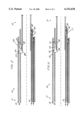
- FIG. 1 is a sectional view through a multi-tube telescopic leg for a camera stand or the like showing the leg in the retracted condition;
- FIG. 2 is a similar view to FIG. 1 showing the inner tube of the leg fully extended;
- FIG. 3 is a similar view to FIG. 1 showing the intermediate tube partially extended
- FIG. 4 is a similar view to FIG. 1 showing a telescopic leg including several intermediate members.
- FIG. 1 of the drawings there is shown a telescopic leg for a camera stand indicated generally at 10 having a head end indicated generally at 11 on which a camera mounting is supported and a foot end indicated generally at 12 to engage the ground.
- the leg comprises three telescopically interconnected tubes comprising a first inner tube 13, an intermediate tube 14 and an outer tube 15.
- the intermediate tube has a locking device engagable with the inner tube 13 and comprising a pair of cooperating wedges 16, 17 spring loaded in a locking direction by a spring indicated at 18.
- the locking device is released by separating the wedges against the action of the spring 18 through a push member in the form of an arcuate cross section sleeve 19 extending coaxially between the first and intermediate sleeves from the head end of the leg.
- a similar locking device is provided at the foot end of the outer tube 15 to engage the intermediate tube and like parts have been allotted the same reference numerals.
- a latch 20 is pivotally mounted in a slot 21 in the intermediate tube 14 towards the foot end thereof and has an outwardly extending projection 22 which is engagable in an aperture 23 in the wall of the outer tube 15.
- the latch has an inwardly projecting abutment 24 which bears on the outer surface of the first tube 13 when the latter is in its retracted condition.
- Extension of the leg is effected by pressing the push members 19 from the head end of the leg to release the locking devices 16 and 17 between the intermediate member and first member and final member and intermediate member respectively.
- the first member 13 can then be extended with respect to the intermediate member as illustrated in FIG. 2 until the end of the first member is drawn beyond the abutment 24 of the latch 20.
- the abutment 24 on the latch then drops behind the end of the inner sleeve 13 extracting the projection 22 from the aperture in the outer sleeve and thereby permitting the intermediate member to extend with respect to the outer sleeve.
- the locking device 16/17 on the intermediate member disengages from the push member 19 allowing the spring 18 to lock the device between the intermediate member and first member so that the first and intermediate members then move together as can be seen in FIG. 3.
- the intermediate member is extended with respect to the outer member 15 as required and the push member controlling its extension is released when the required extension has been reached.
- the leg is collapsed in the reverse manner by pressing the push members 19 to release the locking devices between the final and intermediate sleeve to allow the intermediate sleeve to telescope into the final sleeve re-engaging the locking device between the intermediate and first sleeve with its push member to release the locking action and allow the first sleeve to move inwardly with respect to the intermediate sleeve deflecting the latch outwardly to engage the projection 22 in the aperture 23 to lock the intermediate and final sleeves together and finally to return the first sleeve to its fully retracted starting position, as shown in FIG. 1.
- the telescopic leg is particularly suitable for a tripod form stand suitable for carrying a camera or other optical equipment.
- the head end 11 of the each leg is pivotally mounted on a camera supporting platform which is provided with a device such as a rotary cam for acting on the push members 19 for each of the legs so that operation of one member controls release and retraction of all three legs.
- the arrangement therefore provides a very convenient and easily operated telescopic stand for the camera operator.
Landscapes
- Engineering & Computer Science (AREA)
- General Engineering & Computer Science (AREA)
- Mechanical Engineering (AREA)
- Accessories Of Cameras (AREA)
- Walking Sticks, Umbrellas, And Fans (AREA)
- Ladders (AREA)
- Legs For Furniture In General (AREA)
Abstract
Description
Claims (8)
Applications Claiming Priority (3)
| Application Number | Priority Date | Filing Date | Title |
|---|---|---|---|
| GB9608945 | 1996-04-29 | ||
| GBGB9608945.3A GB9608945D0 (en) | 1996-04-29 | 1996-04-29 | Improvements in or relating to extendible legs for stands or similar appliances |
| PCT/GB1997/000227 WO1997041383A1 (en) | 1996-04-29 | 1997-01-24 | Improvements in or relating to extendable legs for stands or similar appliances |
Publications (1)
| Publication Number | Publication Date |
|---|---|
| US6152638A true US6152638A (en) | 2000-11-28 |
Family
ID=10792886
Family Applications (1)
| Application Number | Title | Priority Date | Filing Date |
|---|---|---|---|
| US09/171,872 Expired - Lifetime US6152638A (en) | 1996-04-29 | 1997-01-24 | Extendable legs for stands or similar appliances |
Country Status (7)
| Country | Link |
|---|---|
| US (1) | US6152638A (en) |
| JP (1) | JP3450860B2 (en) |
| CN (1) | CN1080400C (en) |
| AU (1) | AU709650B2 (en) |
| DE (1) | DE19781733T1 (en) |
| GB (2) | GB9608945D0 (en) |
| WO (1) | WO1997041383A1 (en) |
Cited By (16)
| Publication number | Priority date | Publication date | Assignee | Title |
|---|---|---|---|---|
| US6536723B1 (en) * | 1999-08-24 | 2003-03-25 | Nihon Nelbon Seiki Kogyo Kabushiki Kaisha | Tripod with improved telescopic extension |
| US20040206879A1 (en) * | 2001-05-10 | 2004-10-21 | Steyn Jasper L | Multi-legged equipment support for cameras, spotting telescopes and the like and jam-plate lock for same |
| WO2008028490A1 (en) * | 2006-09-07 | 2008-03-13 | Falck Schmidt Defence Systems A/S | Telescopic mast having reduced play |
| US20080253832A1 (en) * | 2007-04-13 | 2008-10-16 | O'connell Tim | Non-interfering spring operated button assembly |
| US20100146873A1 (en) * | 2007-04-16 | 2010-06-17 | Falck Schmidt Defence Systems A/S | Telescoping mast |
| US7845602B1 (en) | 2006-02-09 | 2010-12-07 | Primos, Inc. | Telescoping support stand apparatus |
| US20110173867A1 (en) * | 2010-01-15 | 2011-07-21 | Desert Manufacturing, Llc | Adjustable support for firearms |
| US8146876B1 (en) | 2006-02-09 | 2012-04-03 | Primos, Inc. | Telescoping support stand apparatus |
| US9234362B2 (en) * | 2012-09-11 | 2016-01-12 | Steeldeck Industries Limited | Rostrum and rostrum support structure |
| US9670948B1 (en) * | 2016-01-27 | 2017-06-06 | The Will-Burt Company | Latch for sequentially extended mechanical mast |
| US10539170B2 (en) | 2015-12-31 | 2020-01-21 | Sleep Number Corporation | Foundation and frame for bed |
| WO2022000032A1 (en) * | 2020-06-30 | 2022-01-06 | Clemseven Holdings Pty Ltd | A support leg |
| US11226067B1 (en) * | 2018-12-11 | 2022-01-18 | Amazon Technologies, Inc. | Mechanism for sequenced deployment of a mast |
| US11383394B1 (en) | 2018-12-11 | 2022-07-12 | Amazon Technologies, Inc. | Extensible mast for an autonomous mobile device |
| US11396266B1 (en) * | 2018-12-11 | 2022-07-26 | Amazon Technologies, Inc. | Autonomous mobile device with extensible mast |
| US11467628B1 (en) | 2018-12-11 | 2022-10-11 | Amazon Technologies, Inc. | Pan and tilt assembly for autonomous mobile device |
Families Citing this family (7)
| Publication number | Priority date | Publication date | Assignee | Title |
|---|---|---|---|---|
| IL134285A0 (en) * | 2000-01-30 | 2001-04-30 | Sherwin Daniel | Tripod |
| IT1315720B1 (en) * | 2000-07-14 | 2003-03-18 | Manfrotto Lino & C Spa | TELESCOPIC SUPPORT FOR OPTICAL, PHOTOGRAPHIC AND SIMILAR EQUIPMENT |
| AUPQ910500A0 (en) | 2000-07-31 | 2000-08-24 | R.E. Miller Pty. Ltd. | Support means |
| ITPD20030020A1 (en) * | 2003-01-30 | 2004-07-31 | Manfrotto Lino & C Spa | FOOT FOR OPTICAL OR PHOTOGRAPHIC SUPPORTS |
| ITRM20060613A1 (en) * | 2006-11-13 | 2008-05-14 | Cartoni S P A | IMPROVED TRIPOD |
| JP4321874B2 (en) * | 2007-03-19 | 2009-08-26 | ベルボン株式会社 | Telescopic device and tripod |
| GB2536277B (en) * | 2015-03-12 | 2018-03-07 | Vitec Group Plc | An extendible tripod leg |
Citations (11)
| Publication number | Priority date | Publication date | Assignee | Title |
|---|---|---|---|---|
| US2455525A (en) * | 1945-09-14 | 1948-12-07 | Schulz Herman | Tripod |
| US2600735A (en) * | 1948-04-29 | 1952-06-17 | Corneliussen Carl | Longitudinally adjustable legs, for example for seats, stools, or the like |
| GB1260368A (en) * | 1968-03-29 | 1972-01-19 | Heer & Co | Improvements in stands for photographic apparatus |
| US4029279A (en) * | 1975-07-25 | 1977-06-14 | Koma Nakatani | Device for holding each of the legs of a tripod |
| US4174900A (en) * | 1977-06-29 | 1979-11-20 | Mitsuwa Shashin Kogyo Kabushiki Kaisha | Camera tripod |
| EP0063783A1 (en) * | 1981-04-28 | 1982-11-03 | DORNIER SYSTEM GmbH | Telescopic extension device |
| US4362415A (en) * | 1981-03-31 | 1982-12-07 | Norco, Inc. | Extensible and retractable strut with safety latch |
| US4793197A (en) * | 1986-09-10 | 1988-12-27 | Dornier Gmbh | Telescoping device |
| US5492430A (en) * | 1994-10-14 | 1996-02-20 | Carl A. Hammoms | Telescopic tubes locking device |
| US5593239A (en) * | 1994-04-28 | 1997-01-14 | Tracor, Inc. | Extendable support pole |
| US5660495A (en) * | 1995-11-02 | 1997-08-26 | Japan Skyrobot Co., Ltd | Locking-unlocking mechanism for telescopic device |
-
1996
- 1996-04-29 GB GBGB9608945.3A patent/GB9608945D0/en active Pending
-
1997
- 1997-01-24 WO PCT/GB1997/000227 patent/WO1997041383A1/en not_active Ceased
- 1997-01-24 JP JP53864897A patent/JP3450860B2/en not_active Expired - Fee Related
- 1997-01-24 US US09/171,872 patent/US6152638A/en not_active Expired - Lifetime
- 1997-01-24 CN CN97195697A patent/CN1080400C/en not_active Expired - Fee Related
- 1997-01-24 DE DE19781733T patent/DE19781733T1/en not_active Withdrawn
- 1997-01-24 AU AU14533/97A patent/AU709650B2/en not_active Ceased
- 1997-01-24 GB GB9823051A patent/GB2331697B/en not_active Expired - Fee Related
Patent Citations (11)
| Publication number | Priority date | Publication date | Assignee | Title |
|---|---|---|---|---|
| US2455525A (en) * | 1945-09-14 | 1948-12-07 | Schulz Herman | Tripod |
| US2600735A (en) * | 1948-04-29 | 1952-06-17 | Corneliussen Carl | Longitudinally adjustable legs, for example for seats, stools, or the like |
| GB1260368A (en) * | 1968-03-29 | 1972-01-19 | Heer & Co | Improvements in stands for photographic apparatus |
| US4029279A (en) * | 1975-07-25 | 1977-06-14 | Koma Nakatani | Device for holding each of the legs of a tripod |
| US4174900A (en) * | 1977-06-29 | 1979-11-20 | Mitsuwa Shashin Kogyo Kabushiki Kaisha | Camera tripod |
| US4362415A (en) * | 1981-03-31 | 1982-12-07 | Norco, Inc. | Extensible and retractable strut with safety latch |
| EP0063783A1 (en) * | 1981-04-28 | 1982-11-03 | DORNIER SYSTEM GmbH | Telescopic extension device |
| US4793197A (en) * | 1986-09-10 | 1988-12-27 | Dornier Gmbh | Telescoping device |
| US5593239A (en) * | 1994-04-28 | 1997-01-14 | Tracor, Inc. | Extendable support pole |
| US5492430A (en) * | 1994-10-14 | 1996-02-20 | Carl A. Hammoms | Telescopic tubes locking device |
| US5660495A (en) * | 1995-11-02 | 1997-08-26 | Japan Skyrobot Co., Ltd | Locking-unlocking mechanism for telescopic device |
Cited By (28)
| Publication number | Priority date | Publication date | Assignee | Title |
|---|---|---|---|---|
| US6536723B1 (en) * | 1999-08-24 | 2003-03-25 | Nihon Nelbon Seiki Kogyo Kabushiki Kaisha | Tripod with improved telescopic extension |
| US20040206879A1 (en) * | 2001-05-10 | 2004-10-21 | Steyn Jasper L | Multi-legged equipment support for cameras, spotting telescopes and the like and jam-plate lock for same |
| US7178767B2 (en) | 2001-05-10 | 2007-02-20 | Massachusetts Institute Of Technology | Multi-legged equipment support for cameras, spotting telescopes and the like and jam-plate lock for same |
| US8714508B1 (en) | 2006-02-09 | 2014-05-06 | Primos, Inc. | Telescoping support stand apparatus |
| US9010710B1 (en) | 2006-02-09 | 2015-04-21 | Primos, Inc. | Telescoping support stand apparatus |
| US8820693B1 (en) | 2006-02-09 | 2014-09-02 | Primos, Inc. | Telescoping support stand apparatus |
| US8469326B1 (en) | 2006-02-09 | 2013-06-25 | Primos, Inc. | Telescoping support stand apparatus |
| US7845602B1 (en) | 2006-02-09 | 2010-12-07 | Primos, Inc. | Telescoping support stand apparatus |
| US8256732B1 (en) | 2006-02-09 | 2012-09-04 | Primos, Inc. | Telescoping support stand apparatus |
| US8146876B1 (en) | 2006-02-09 | 2012-04-03 | Primos, Inc. | Telescoping support stand apparatus |
| US8695286B2 (en) | 2006-09-07 | 2014-04-15 | Falck Schmidt Defence Systems A/S | Telescopic mast having reduced play |
| WO2008028490A1 (en) * | 2006-09-07 | 2008-03-13 | Falck Schmidt Defence Systems A/S | Telescopic mast having reduced play |
| US20100050557A1 (en) * | 2006-09-07 | 2010-03-04 | Falck Schmidt Defence Systems A/S | Telescopic mast having reduced play |
| US20080253832A1 (en) * | 2007-04-13 | 2008-10-16 | O'connell Tim | Non-interfering spring operated button assembly |
| US20100146873A1 (en) * | 2007-04-16 | 2010-06-17 | Falck Schmidt Defence Systems A/S | Telescoping mast |
| US8661744B2 (en) * | 2007-04-16 | 2014-03-04 | Falck Schmidt Defence Systems A/S | Telescoping mast |
| US20110173867A1 (en) * | 2010-01-15 | 2011-07-21 | Desert Manufacturing, Llc | Adjustable support for firearms |
| US9234362B2 (en) * | 2012-09-11 | 2016-01-12 | Steeldeck Industries Limited | Rostrum and rostrum support structure |
| US12117028B2 (en) | 2015-12-31 | 2024-10-15 | Sleep Number Corporation | Foundation and frame for bed |
| US10539170B2 (en) | 2015-12-31 | 2020-01-21 | Sleep Number Corporation | Foundation and frame for bed |
| US11085479B2 (en) | 2015-12-31 | 2021-08-10 | Sleep Number Corporation | Foundation and frame for bed |
| US9670948B1 (en) * | 2016-01-27 | 2017-06-06 | The Will-Burt Company | Latch for sequentially extended mechanical mast |
| US11226067B1 (en) * | 2018-12-11 | 2022-01-18 | Amazon Technologies, Inc. | Mechanism for sequenced deployment of a mast |
| US11383394B1 (en) | 2018-12-11 | 2022-07-12 | Amazon Technologies, Inc. | Extensible mast for an autonomous mobile device |
| US11396266B1 (en) * | 2018-12-11 | 2022-07-26 | Amazon Technologies, Inc. | Autonomous mobile device with extensible mast |
| US11467628B1 (en) | 2018-12-11 | 2022-10-11 | Amazon Technologies, Inc. | Pan and tilt assembly for autonomous mobile device |
| WO2022000032A1 (en) * | 2020-06-30 | 2022-01-06 | Clemseven Holdings Pty Ltd | A support leg |
| US12297955B2 (en) | 2020-06-30 | 2025-05-13 | Clemseven Holdings Pty Ltd | Support leg |
Also Published As
| Publication number | Publication date |
|---|---|
| AU709650B2 (en) | 1999-09-02 |
| AU1453397A (en) | 1997-11-19 |
| CN1222961A (en) | 1999-07-14 |
| JP2000504095A (en) | 2000-04-04 |
| DE19781733T1 (en) | 1999-04-08 |
| JP3450860B2 (en) | 2003-09-29 |
| WO1997041383A1 (en) | 1997-11-06 |
| GB9823051D0 (en) | 1998-12-16 |
| CN1080400C (en) | 2002-03-06 |
| GB2331697A (en) | 1999-06-02 |
| GB2331697B (en) | 2000-05-31 |
| GB9608945D0 (en) | 1996-07-03 |
Similar Documents
| Publication | Publication Date | Title |
|---|---|---|
| US6152638A (en) | Extendable legs for stands or similar appliances | |
| JP4128953B2 (en) | Stabilizer with telescoping rod for tripod etc. | |
| US6478037B2 (en) | Foldable sunshade with a tiltable canopy | |
| CN108361521B (en) | Tripod leg telescopic opening mechanism and adjusting method thereof | |
| US10969657B2 (en) | Support stand for photography and the like having a plurality of rotatable legs | |
| US3064932A (en) | Adjustable stand for cameras, lights and the like | |
| CN101346576B (en) | Adjustable telescopic supporting device | |
| JP2001235092A (en) | Tripod mount | |
| US2455525A (en) | Tripod | |
| CN112334700B (en) | Support device for video/photographic equipment | |
| US6260238B1 (en) | Adjustable length handle for flat finishers | |
| EP4078010B1 (en) | Tripod for shooting equipment | |
| US20080283713A1 (en) | Support Particularly for Optical or Photographic Use | |
| US2430649A (en) | Tripod | |
| US5678843A (en) | Luggage trolley structure | |
| US20210381312A1 (en) | A stabiliser system for a collapsible ladder | |
| SE9202115L (en) | Lockable, telescoping device | |
| CN115654319B (en) | Supporting device | |
| US3292956A (en) | Clamping arrangement for pipes | |
| JP3022902U (en) | Leg structure of tripod | |
| CN113701020A (en) | Multifunctional support | |
| US20070125915A1 (en) | Multiple telescoping tube comprising a load-controlled locking device | |
| CN222351996U (en) | Stand and use its photographic cloud platform | |
| JPH074893A (en) | Rod expanding/contracting mechanism and nightstick using extending or retracting mechanism | |
| US1750273A (en) | Music stand |
Legal Events
| Date | Code | Title | Description |
|---|---|---|---|
| AS | Assignment |
Owner name: VITEC GROUP, PLC, UNITED KINGDOM Free format text: ASSIGNMENT OF ASSIGNORS INTEREST;ASSIGNOR:LINDSAY, RICHARD ARTHUR;REEL/FRAME:009923/0812 Effective date: 19981030 |
|
| STCF | Information on status: patent grant |
Free format text: PATENTED CASE |
|
| AS | Assignment |
Owner name: SEALY TECHNOLOGY LLC, NORTH CAROLINA Free format text: ASSIGNMENT OF ASSIGNORS INTEREST;ASSIGNORS:DEMOSS, LARRY;ZOU, JOE;REEL/FRAME:011297/0095 Effective date: 20001121 |
|
| AS | Assignment |
Owner name: VITEC GROUP PLC, THE, UNITED KINGDOM Free format text: CHANGE OF NAME;ASSIGNOR:VITEC GROUP PLC;REEL/FRAME:014066/0055 Effective date: 20010417 |
|
| FPAY | Fee payment |
Year of fee payment: 4 |
|
| FPAY | Fee payment |
Year of fee payment: 8 |
|
| FPAY | Fee payment |
Year of fee payment: 12 |
|
| AS | Assignment |
Owner name: BANK OF AMERICA, N.A., AS COLLATERAL AGENT, TEXAS Free format text: PATENT SECURITY AGREEMENT;ASSIGNORS:TEMPUR-PEDIC MANAGEMENT, LLC;SEALY TECHNOLOGY LLC;REEL/FRAME:030165/0264 Effective date: 20130318 |
|
| AS | Assignment |
Owner name: SEALY TECHNOLOGY LLC, NORTH CAROLINA Free format text: RELEASE OF SECURITY INTEREST IN PATENT RIGHTS;ASSIGNOR:BANK OF AMERICA, N.A., AS COLLATERAL AGENT;REEL/FRAME:038403/0036 Effective date: 20160406 Owner name: TEMPUR-PEDIC MANAGEMENT, LLC, KENTUCKY Free format text: RELEASE OF SECURITY INTEREST IN PATENT RIGHTS;ASSIGNOR:BANK OF AMERICA, N.A., AS COLLATERAL AGENT;REEL/FRAME:038403/0036 Effective date: 20160406 |