US6152388A - Spray nozzle apparatus - Google Patents
Spray nozzle apparatus Download PDFInfo
- Publication number
- US6152388A US6152388A US09/317,331 US31733199A US6152388A US 6152388 A US6152388 A US 6152388A US 31733199 A US31733199 A US 31733199A US 6152388 A US6152388 A US 6152388A
- Authority
- US
- United States
- Prior art keywords
- pipe
- liquid
- spray nozzle
- nipple
- nozzle apparatus
- Prior art date
- Legal status (The legal status is an assumption and is not a legal conclusion. Google has not performed a legal analysis and makes no representation as to the accuracy of the status listed.)
- Expired - Fee Related
Links
- 239000007921 spray Substances 0.000 title claims abstract description 15
- 239000007788 liquid Substances 0.000 claims abstract description 28
- 210000002445 nipple Anatomy 0.000 claims abstract description 16
- 238000005507 spraying Methods 0.000 abstract description 6
- 230000000712 assembly Effects 0.000 description 3
- 238000000429 assembly Methods 0.000 description 3
- 241000196324 Embryophyta Species 0.000 description 2
- 239000003518 caustics Substances 0.000 description 1
- 238000009313 farming Methods 0.000 description 1
- 239000003337 fertilizer Substances 0.000 description 1
- 238000002347 injection Methods 0.000 description 1
- 239000007924 injection Substances 0.000 description 1
- 230000013011 mating Effects 0.000 description 1
- 238000009428 plumbing Methods 0.000 description 1
- 238000011144 upstream manufacturing Methods 0.000 description 1
- 239000002699 waste material Substances 0.000 description 1
Images
Classifications
-
- B—PERFORMING OPERATIONS; TRANSPORTING
- B05—SPRAYING OR ATOMISING IN GENERAL; APPLYING FLUENT MATERIALS TO SURFACES, IN GENERAL
- B05B—SPRAYING APPARATUS; ATOMISING APPARATUS; NOZZLES
- B05B15/00—Details of spraying plant or spraying apparatus not otherwise provided for; Accessories
- B05B15/60—Arrangements for mounting, supporting or holding spraying apparatus
- B05B15/65—Mounting arrangements for fluid connection of the spraying apparatus or its outlets to flow conduits
- B05B15/658—Mounting arrangements for fluid connection of the spraying apparatus or its outlets to flow conduits the spraying apparatus or its outlet axis being perpendicular to the flow conduit
Definitions
- the invention is directed to spray nozzle devices used on liquid spraying implements commonly having booms for supporting a plurality of such spray nozzle devices therealong.
- the spraying of various liquids on agricultural fields is common with respect to most types of farming and for most types of crops.
- the liquids tend to be expensive. They can also be caustic or otherwise pose some danger, not only to implement operators, but to plant life for which the liquids may not be designed. It is necessary to carefully control spraying. In this regard, it is important to fully clean the spraying implement when switching from one liquid to be sprayed to another. In particular, there has been the problem that remnants of the liquid last sprayed remain in the system when a new liquid to be sprayed is loaded in the system.
- the spray nozzle apparatus of the present invention provides apparatus which allows for complete drainage of liquid from a distribution pipe when the spray system has been shut-off.
- the spray nozzle apparatus of the present invention attaches with a clamp to a distribution pipe.
- the pipe has a wall with outer and inner surface and has an opening at a lower most location along the wall.
- the apparatus includes a body with a saddle for mating with the clamp.
- the body includes a nipple protruding up from the saddle so as to project through the opening in the pipe when the clamp attaches the assembly to the pipe.
- the nipple has a notch in opposite walls such that the notches are beneath the inner surface of the wall of the pipe when the assembly is attached to the pipe so that liquid cannot accumulate between the nipple and the inner surface of the pipe.
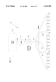
- FIG. 1 is a schematic illustration of a spraying instrument having nozzle apparatus in accordance with the present invention
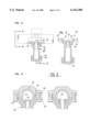
- FIG. 2 is a cross-sectional view of spray nozzle apparatus in accordance with the present invention, with a portion of the saddle broken away for clarity;
- FIG. 3 is a cross-sectional view taken along the line 3--3 of FIG. 2;
- FIG. 4 is a view looking into the pipe as taken along line 4--4 of FIG. 2;
- FIG. 5 is a view similar to FIG. 4 showing conventional spray nozzle apparatus.
- System 10 could be vastly more complex and is intended for mounting on a spray implement having a boom structure. System 10, however, has purposely been made simple for the sake of clarity.
- System I0 includes a tank 12 for providing a reservoir for the liquid to be sprayed.
- a pump 14 receives liquid via a tube or pipe 16. The liquid to be sprayed is pumped via a tube or pipe 18 which has a shut-off valve 20 therein to a manifold 22.
- a plurality of tubes or pipes 24, 26, 28 are directed in a fashion to be supported by the boom structure (shown partially schematically).
- a plurality of nozzle assemblies 30 are mounted on, for example, pipe 26.
- FIG. 2 A representative form of nozzle assembly 30 in accordance with the present invention is shown in FIG. 2.
- the nozzle assembly 30 includes a body 32 and a nozzle tip 34.
- Body 32 includes a main portion 36 with an engagement portion 38 at the downstream end and a saddle 40 at the upstream end.
- a nozzle tip 34 engages with engagement portion 38 to provide a nozzle 42 at the downstream end of the spray nozzle assembly 30.
- saddle 40 includes a pipe engagement portion 44 and a pair of first flanges 46 on opposite sides thereof. As shown in FIG. 4, saddle 40 mates with clamp 48 to attach spray nozzle assembly 30 to pipe 26. A pair of screws 50 on opposite sides of pipe 26 attached flanges 46 to clamp 48.
- saddle portion 44 has a nipple 52 extending upwardly from a central location thereof.
- An open passage 54 is provided centrally of nipple 52 and extends completely through body 32 to communicate with nozzle 42.
- liquid from tank 12 flows through line 16, pump 14, line 18 when shut-off valve 20 is open to manifold 22. Some of the liquid is directed into the various branches of the system, including pipe 26. Liquid flows from pipe 26 into passage 54 for ejection from nozzle 42. In this regard, passage 54 opens into the interior of pipe 26.
- Pipe 26 includes openings 55 along the lower most portion of the pipe.
- nipple 52 extends completely through and above the opening in pipe 26. It is necessary that nipple 52 extend beyond the internal surface of pipe 26 in order to provide sufficiently strong structure to maintain nozzle assembly 30 at the desired location without breaking off nipple 52.
- a conventional nozzle apparatus protrudes into the interior of a delivery pipe such that when liquid is no longer being pumped through the system, some of the liquid 56 remains in the region between nipple 58 and the inner surface 60 of the delivery pipe.
- the presence of the remnant liquid 56 is troublesome in that it is a costly waste of the liquid, it may result in some of the liquid being distributed as a first injection on a new field where such liquid is undesirable and in fact harmful, and it could result in a safety problem if it were expected that all previous liquid in the system had in fact been removed from the system.
- the present invention includes a notch 62 in the opposite walls of nipple 52 so that such notches 62 preferably extend beneath the inner surface 64 of pipe 26 along the longitudinal direction of pipe 26.
- body 36 of apparatus 30 is representative.
- Body 36 could include multiple engagement portions 38 for nozzle tips 34.
- Body 36 could also include a check valve assembly or other stop-type valves.
- the details of body 36 beneath saddle portion 40 are not a part of the present invention.
Landscapes
- Nozzles (AREA)
Abstract
Spray nozzle apparatus for use along the boom of a liquid spraying implement. The spray nozzle apparatus includes a nipple extending upwardly into the distribution pipe when the body of the spray nozzle assembly is clamped to the pipe. The nipple includes notches along the longitudinal direction of the pipe so that when the system is drained, all liquid can drain from the pipe through the notches.
Description
The invention is directed to spray nozzle devices used on liquid spraying implements commonly having booms for supporting a plurality of such spray nozzle devices therealong.
The spraying of various liquids on agricultural fields, for example, fertilizers, weed killers, etc., is common with respect to most types of farming and for most types of crops. The liquids tend to be expensive. They can also be caustic or otherwise pose some danger, not only to implement operators, but to plant life for which the liquids may not be designed. It is necessary to carefully control spraying. In this regard, it is important to fully clean the spraying implement when switching from one liquid to be sprayed to another. In particular, there has been the problem that remnants of the liquid last sprayed remain in the system when a new liquid to be sprayed is loaded in the system.
The spray nozzle apparatus of the present invention provides apparatus which allows for complete drainage of liquid from a distribution pipe when the spray system has been shut-off. In this regard, the spray nozzle apparatus of the present invention attaches with a clamp to a distribution pipe. The pipe has a wall with outer and inner surface and has an opening at a lower most location along the wall. The apparatus includes a body with a saddle for mating with the clamp. The body includes a nipple protruding up from the saddle so as to project through the opening in the pipe when the clamp attaches the assembly to the pipe. The nipple has a notch in opposite walls such that the notches are beneath the inner surface of the wall of the pipe when the assembly is attached to the pipe so that liquid cannot accumulate between the nipple and the inner surface of the pipe.
FIG. 1 is a schematic illustration of a spraying instrument having nozzle apparatus in accordance with the present invention;
FIG. 2 is a cross-sectional view of spray nozzle apparatus in accordance with the present invention, with a portion of the saddle broken away for clarity;
FIG. 3 is a cross-sectional view taken along the line 3--3 of FIG. 2;
FIG. 4 is a view looking into the pipe as taken along line 4--4 of FIG. 2;
FIG. 5 is a view similar to FIG. 4 showing conventional spray nozzle apparatus.
Referring now to the drawings wherein like reference numerals designate identical or corresponding parts throughout the several views, and more particularly to FIG. 1, a representative plumbing system is designated generally by the numeral 10. System 10 could be vastly more complex and is intended for mounting on a spray implement having a boom structure. System 10, however, has purposely been made simple for the sake of clarity. System I0 includes a tank 12 for providing a reservoir for the liquid to be sprayed. A pump 14 receives liquid via a tube or pipe 16. The liquid to be sprayed is pumped via a tube or pipe 18 which has a shut-off valve 20 therein to a manifold 22. A plurality of tubes or pipes 24, 26, 28 are directed in a fashion to be supported by the boom structure (shown partially schematically). A plurality of nozzle assemblies 30 are mounted on, for example, pipe 26.
A representative form of nozzle assembly 30 in accordance with the present invention is shown in FIG. 2. The nozzle assembly 30 includes a body 32 and a nozzle tip 34. Body 32 includes a main portion 36 with an engagement portion 38 at the downstream end and a saddle 40 at the upstream end. A nozzle tip 34 engages with engagement portion 38 to provide a nozzle 42 at the downstream end of the spray nozzle assembly 30.
As shown in FIG. 3, saddle 40 includes a pipe engagement portion 44 and a pair of first flanges 46 on opposite sides thereof. As shown in FIG. 4, saddle 40 mates with clamp 48 to attach spray nozzle assembly 30 to pipe 26. A pair of screws 50 on opposite sides of pipe 26 attached flanges 46 to clamp 48.
Assuming the pipe receiving semi-cylindrical internal portion of saddle portion 44 opens upwardly, saddle portion 44 has a nipple 52 extending upwardly from a central location thereof. An open passage 54 is provided centrally of nipple 52 and extends completely through body 32 to communicate with nozzle 42. As shown in FIG. 1, liquid from tank 12 flows through line 16, pump 14, line 18 when shut-off valve 20 is open to manifold 22. Some of the liquid is directed into the various branches of the system, including pipe 26. Liquid flows from pipe 26 into passage 54 for ejection from nozzle 42. In this regard, passage 54 opens into the interior of pipe 26. Pipe 26 includes openings 55 along the lower most portion of the pipe. The nipple of the various assemblies 30 extend into these openings to locate assemblies 30 at equal spacings along pipe 26. As shown in FIG. 4, nipple 52 extends completely through and above the opening in pipe 26. It is necessary that nipple 52 extend beyond the internal surface of pipe 26 in order to provide sufficiently strong structure to maintain nozzle assembly 30 at the desired location without breaking off nipple 52.
As shown in FIG. 5, a conventional nozzle apparatus protrudes into the interior of a delivery pipe such that when liquid is no longer being pumped through the system, some of the liquid 56 remains in the region between nipple 58 and the inner surface 60 of the delivery pipe. The presence of the remnant liquid 56 is troublesome in that it is a costly waste of the liquid, it may result in some of the liquid being distributed as a first injection on a new field where such liquid is undesirable and in fact harmful, and it could result in a safety problem if it were expected that all previous liquid in the system had in fact been removed from the system. The present invention includes a notch 62 in the opposite walls of nipple 52 so that such notches 62 preferably extend beneath the inner surface 64 of pipe 26 along the longitudinal direction of pipe 26. As a result, when liquid from tank 12 is shut off at valve 20, all of the liquid will drain from the system since all liquid in pipe 26 will be allowed to flow through notches 62 into passage 54 and drain or be injected from nozzle 42.
It is understood that body 36 of apparatus 30 is representative. Body 36 could include multiple engagement portions 38 for nozzle tips 34. Body 36 could also include a check valve assembly or other stop-type valves. The details of body 36 beneath saddle portion 40 are not a part of the present invention.
Although characteristics and advantages of the present invention, together with details of structure and function, have been described or are clear from the present disclosure, it is understood that the disclosure is illustrative only. Changes made, especially in matters of shape, size and arrangement, to the full extent extended by the general meaning of the terms in which the appended claims are expressed, are considered to be within the principle of the invention.
Claims (2)
1. Spray nozzle apparatus for attachment to a pipe, said apparatus comprising a body with a saddle, said body including a nipple protruding up from said saddle so as to project through an opening in said pipe when said assembly is clamped to said pipe, said nipple having a notch in opposite walls so that liquid cannot accumulate between said nipple and the inner surface of said pipe.
2. The apparatus in accordance with claim 1 wherein said notches extend beneath the inner surface of the wall of said pipe when said body is clamped to said pipe.
Priority Applications (1)
| Application Number | Priority Date | Filing Date | Title |
|---|---|---|---|
| US09/317,331 US6152388A (en) | 1999-05-24 | 1999-05-24 | Spray nozzle apparatus |
Applications Claiming Priority (1)
| Application Number | Priority Date | Filing Date | Title |
|---|---|---|---|
| US09/317,331 US6152388A (en) | 1999-05-24 | 1999-05-24 | Spray nozzle apparatus |
Publications (1)
| Publication Number | Publication Date |
|---|---|
| US6152388A true US6152388A (en) | 2000-11-28 |
Family
ID=23233188
Family Applications (1)
| Application Number | Title | Priority Date | Filing Date |
|---|---|---|---|
| US09/317,331 Expired - Fee Related US6152388A (en) | 1999-05-24 | 1999-05-24 | Spray nozzle apparatus |
Country Status (1)
| Country | Link |
|---|---|
| US (1) | US6152388A (en) |
Cited By (12)
| Publication number | Priority date | Publication date | Assignee | Title |
|---|---|---|---|---|
| US20040046040A1 (en) * | 2002-08-19 | 2004-03-11 | Micheli Paul R. | Spray gun with improved atomization |
| US20040118949A1 (en) * | 2002-12-23 | 2004-06-24 | Marks Kipley Roydon | Shower Nozzle |
| US20040124283A1 (en) * | 2002-11-14 | 2004-07-01 | Arag S.R.L. | Branching unit for fluid conveyance pipes, particularly for agricultural treatments or the like |
| US20060000928A1 (en) * | 2004-06-30 | 2006-01-05 | Micheli Paul R | Fluid atomizing system and method |
| US20060214027A1 (en) * | 2004-06-30 | 2006-09-28 | Micheli Paul R | Fluid atomizing system and method |
| US20080048055A1 (en) * | 2002-08-19 | 2008-02-28 | Illinois Tool Works Inc. | Spray gun having mechanism for internally swirling and breaking up a fluid |
| US20080087750A1 (en) * | 2006-09-27 | 2008-04-17 | Simon Waddelow | Nozzle body apparatus |
| US20090044329A1 (en) * | 2007-08-14 | 2009-02-19 | Matthew Kestian | Self-supporting shower head system |
| US9140398B2 (en) | 2010-04-02 | 2015-09-22 | Pentair Flow Technologies, Llc | Air aspiration device |
| EP3090630A1 (en) * | 2015-05-04 | 2016-11-09 | Deere & Company | Sprayer |
| WO2021105819A1 (en) * | 2019-11-26 | 2021-06-03 | Advanced Sterilization Products, Inc. | Endoscope decontamination system with spray nozzle |
| US11592134B2 (en) * | 2017-12-06 | 2023-02-28 | Agrotop Gmbh | Apparatus for spreading fluids and in particular fertilizers, pesticides and similar |
Citations (3)
| Publication number | Priority date | Publication date | Assignee | Title |
|---|---|---|---|---|
| US2946518A (en) * | 1957-10-29 | 1960-07-26 | Spraying Systems Co | Pipe side spray nozzle and clamp |
| US3009655A (en) * | 1960-01-18 | 1961-11-21 | John E Palmer | Spray nozzle devices |
| US5234161A (en) * | 1992-05-08 | 1993-08-10 | Baltimore Aircoil Company | Counterflow spray nozzle |
-
1999
- 1999-05-24 US US09/317,331 patent/US6152388A/en not_active Expired - Fee Related
Patent Citations (3)
| Publication number | Priority date | Publication date | Assignee | Title |
|---|---|---|---|---|
| US2946518A (en) * | 1957-10-29 | 1960-07-26 | Spraying Systems Co | Pipe side spray nozzle and clamp |
| US3009655A (en) * | 1960-01-18 | 1961-11-21 | John E Palmer | Spray nozzle devices |
| US5234161A (en) * | 1992-05-08 | 1993-08-10 | Baltimore Aircoil Company | Counterflow spray nozzle |
Cited By (21)
| Publication number | Priority date | Publication date | Assignee | Title |
|---|---|---|---|---|
| US7762476B2 (en) | 2002-08-19 | 2010-07-27 | Illinois Tool Works Inc. | Spray gun with improved atomization |
| US8640976B2 (en) | 2002-08-19 | 2014-02-04 | Paul R. Micheli | Spray gun having mechanism for internally swirling and breaking up a fluid |
| US20040046040A1 (en) * | 2002-08-19 | 2004-03-11 | Micheli Paul R. | Spray gun with improved atomization |
| US20080048055A1 (en) * | 2002-08-19 | 2008-02-28 | Illinois Tool Works Inc. | Spray gun having mechanism for internally swirling and breaking up a fluid |
| US20040124283A1 (en) * | 2002-11-14 | 2004-07-01 | Arag S.R.L. | Branching unit for fluid conveyance pipes, particularly for agricultural treatments or the like |
| EP1419825A3 (en) * | 2002-11-14 | 2005-07-27 | Arag S.r.l. | Branching unit for fluid conveyance pipes, particularly for agricultural treatments or the like |
| US20040118949A1 (en) * | 2002-12-23 | 2004-06-24 | Marks Kipley Roydon | Shower Nozzle |
| US7883026B2 (en) | 2004-06-30 | 2011-02-08 | Illinois Tool Works Inc. | Fluid atomizing system and method |
| US20060000928A1 (en) * | 2004-06-30 | 2006-01-05 | Micheli Paul R | Fluid atomizing system and method |
| US7992808B2 (en) | 2004-06-30 | 2011-08-09 | Illinois Tool Works Inc. | Fluid atomizing system and method |
| US20060214027A1 (en) * | 2004-06-30 | 2006-09-28 | Micheli Paul R | Fluid atomizing system and method |
| US7926733B2 (en) | 2004-06-30 | 2011-04-19 | Illinois Tool Works Inc. | Fluid atomizing system and method |
| US7980490B2 (en) | 2006-09-27 | 2011-07-19 | Sta-Rite Industries, Llc | Nozzle body apparatus |
| US20080087750A1 (en) * | 2006-09-27 | 2008-04-17 | Simon Waddelow | Nozzle body apparatus |
| US20090044329A1 (en) * | 2007-08-14 | 2009-02-19 | Matthew Kestian | Self-supporting shower head system |
| US9140398B2 (en) | 2010-04-02 | 2015-09-22 | Pentair Flow Technologies, Llc | Air aspiration device |
| US10018291B2 (en) | 2010-04-02 | 2018-07-10 | Pentair Flow Technologies, Llc | Air aspiration device |
| EP3090630A1 (en) * | 2015-05-04 | 2016-11-09 | Deere & Company | Sprayer |
| US10420333B2 (en) | 2015-05-04 | 2019-09-24 | Deere & Company | Spray assembly for boom sprayer |
| US11592134B2 (en) * | 2017-12-06 | 2023-02-28 | Agrotop Gmbh | Apparatus for spreading fluids and in particular fertilizers, pesticides and similar |
| WO2021105819A1 (en) * | 2019-11-26 | 2021-06-03 | Advanced Sterilization Products, Inc. | Endoscope decontamination system with spray nozzle |
Similar Documents
| Publication | Publication Date | Title |
|---|---|---|
| US6152388A (en) | Spray nozzle apparatus | |
| US8894022B2 (en) | Variable diameter hose mounting system | |
| US5158105A (en) | Anti-siphon freezeless hydrant | |
| US8910911B2 (en) | Plumbing mount for agricultural sprayer | |
| US8985532B2 (en) | Modular boom mounting system for agriculture sprayer | |
| US3685735A (en) | Irrigating apparatus | |
| US10362728B2 (en) | Flow diverter for a fertilization system | |
| US6302335B1 (en) | Lawn sprinkler system | |
| KR100844377B1 (en) | Rotary spray tank cleaning device and water tank for village waterworks | |
| US6540156B2 (en) | Above-ground and in-ground fertilizer and irrigation apparatus | |
| US5261607A (en) | Water sprayer assembly and fluid coupling device particularly useful therein | |
| US5617999A (en) | Connector member assembly for use with sprinkler system | |
| US7478765B2 (en) | Spray apparatus | |
| US10994290B2 (en) | Spray system with rail mounting for an agricultural machine | |
| KR200306609Y1 (en) | Variable opening and shutting drain valve member for drops horse of farm produce a water supply system | |
| US20070235561A1 (en) | Tee valve | |
| US20020027172A1 (en) | Automatic lawn feeder | |
| US10900579B2 (en) | Riser valve manifold | |
| US20210146382A1 (en) | Liquid recirculating valve | |
| GB2237520A (en) | Spray heads. | |
| JPH08309245A (en) | Dust prevention nozzle | |
| US10550564B1 (en) | System for flushing a conduit | |
| CN222459493U (en) | Screw-type electric oil nozzle | |
| CN217905610U (en) | Plant root drip irrigation equipment for garden maintenance | |
| KR200153393Y1 (en) | Nozzle structure of the control device |
Legal Events
| Date | Code | Title | Description |
|---|---|---|---|
| REMI | Maintenance fee reminder mailed | ||
| LAPS | Lapse for failure to pay maintenance fees | ||
| LAPS | Lapse for failure to pay maintenance fees |
Free format text: PATENT EXPIRED FOR FAILURE TO PAY MAINTENANCE FEES (ORIGINAL EVENT CODE: EXP.); ENTITY STATUS OF PATENT OWNER: LARGE ENTITY |
|
| STCH | Information on status: patent discontinuation |
Free format text: PATENT EXPIRED DUE TO NONPAYMENT OF MAINTENANCE FEES UNDER 37 CFR 1.362 |
|
| FP | Lapsed due to failure to pay maintenance fee |
Effective date: 20041128 |