US6151940A - Hydroforming process - Google Patents
Hydroforming process Download PDFInfo
- Publication number
- US6151940A US6151940A US09/325,517 US32551799A US6151940A US 6151940 A US6151940 A US 6151940A US 32551799 A US32551799 A US 32551799A US 6151940 A US6151940 A US 6151940A
- Authority
- US
- United States
- Prior art keywords
- cross
- sectional shape
- wall thickness
- portions
- precursor tube
- Prior art date
- Legal status (The legal status is an assumption and is not a legal conclusion. Google has not performed a legal analysis and makes no representation as to the accuracy of the status listed.)
- Expired - Fee Related
Links
Images
Classifications
-
- B—PERFORMING OPERATIONS; TRANSPORTING
- B21—MECHANICAL METAL-WORKING WITHOUT ESSENTIALLY REMOVING MATERIAL; PUNCHING METAL
- B21D—WORKING OR PROCESSING OF SHEET METAL OR METAL TUBES, RODS OR PROFILES WITHOUT ESSENTIALLY REMOVING MATERIAL; PUNCHING METAL
- B21D26/00—Shaping without cutting otherwise than using rigid devices or tools or yieldable or resilient pads, i.e. applying fluid pressure or magnetic forces
- B21D26/02—Shaping without cutting otherwise than using rigid devices or tools or yieldable or resilient pads, i.e. applying fluid pressure or magnetic forces by applying fluid pressure
- B21D26/033—Deforming tubular bodies
-
- B—PERFORMING OPERATIONS; TRANSPORTING
- B21—MECHANICAL METAL-WORKING WITHOUT ESSENTIALLY REMOVING MATERIAL; PUNCHING METAL
- B21D—WORKING OR PROCESSING OF SHEET METAL OR METAL TUBES, RODS OR PROFILES WITHOUT ESSENTIALLY REMOVING MATERIAL; PUNCHING METAL
- B21D26/00—Shaping without cutting otherwise than using rigid devices or tools or yieldable or resilient pads, i.e. applying fluid pressure or magnetic forces
- B21D26/02—Shaping without cutting otherwise than using rigid devices or tools or yieldable or resilient pads, i.e. applying fluid pressure or magnetic forces by applying fluid pressure
- B21D26/053—Shaping without cutting otherwise than using rigid devices or tools or yieldable or resilient pads, i.e. applying fluid pressure or magnetic forces by applying fluid pressure characterised by the material of the blanks
Definitions
- the present invention relates to a hydroforming process, in particular but not exclusively, for the formation of tubular structural elements as used for example in the manufacture of motor vehicles.
- Hydroforming of tubular components is usually achieved by locating a tubular blank within a mould die containing a mould cavity of the desired shape and feeding hydraulic fluid under pressure into the interior of the tubular blank so as to cause the blank to expand and the material forming the walls of the blank to elongate and flow into contact with the mould cavity and thereby be formed into the desired shape.
- a process for hydroforming an elongate tubular structural element in a mould die the structural element having portions spaced along its length which have different circumferential dimensions, a first of said portions having a first cross-sectional shape defining a minimum outer circumferential dimension C 1 and a second of said portions having a second cross-sectional shape defining a maximum outer circumferential dimension C 2 , the process including the steps of:
- a hydroformed elongate structural element having portions spaced along its length which have different circumferential dimensions, a first of said portions defining a minimum circumferential dimension C 1 and a second of said portions defining a maximum circumferential C 2 , the average wall thickness S 1 of said first portion being greater than the average wall thickness S 2 of said second portion.
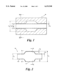
- FIG. 1 is a schematic axial sectional view through a hydroforming die containing a precursor tube according to the present invention prior to hydroforming;
- FIG. 2 is a schematic axial sectional view through an elongate structural element produced from the arrangement shown in FIG. 1;
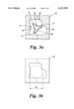
- FIG. 3a is a cross sectional view taken along line III--III in FIG. 1;
- FIG. 3b is a cross-sectional view similar to FIG. 3b diagrammatically showing the relationship between D 0 and the mould cavity;
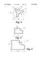
- FIG. 4 is an enlarged cross-sectional view of the precursor tube shown in FIG. 3;
- FIG. 5 is a cross-sectional view taken along line V--V in FIG. 2;
- FIG. 6 is a cross-sectional view taken along line VI--VI in FIG. 2.
- FIG. 2 there is shown an elongate structural element 10 having first, second and third portions 50,51 and 52 respectively.
- the first and third portions 50,52 are of the same cross-sectional shape and dimension along their lengths. These portions define a minimum circumferential dimension C 1 .
- Portion 51 is of the same or different cross-sectional shape as portions 50,51 but is of greater circumferential dimension which in this example is a maximum circumferential dimension C 2 .
- the element 10 is formed by hydroforming techniques in a mould die 16 from a precursor tube 14 which is of constant cross-sectional shape and dimensions along its length.
- the precursor tube 14 is preferably shaped in cross-section so as to have a plurality of axially extending nodes 17 spaced by axially extending channels 18. This enables the circumferential dimension C 0 of the tube to be increased and yet remain within the boundaries of an imaginary minimum diameter D 0 (FIG. 4).
- nodes 17 In the embodiment illustrated in FIG. 3a three axially extending nodes 17 are provided.
- the number and circumferential position of these nodes 17 is chosen bearing in mind the complexity of cross-sectional shape of the element to be formed so as to provided sufficient material for flowing into the radially outermost cavities during the hydroforming process. Usually therefore, the nodes will be arranged to face the radially outermost recesses or cavities 20.
- the cross sectional shape of the element 10 is not complex, for example it may be a simple geometric round or polygonal shape, nodes 17 may not be required and the precursor tube may have a simple geometric cross sectional shape.
- the precursor tube may have a simple geometric cross sectional shape.
- it may be circular in cross section, say of diameter D 0 .
- the wall thickness in the portion 50 of minimum circumferential dimension C 1 will tend to increase compared with that of the precursor tube.
- the diameter D 0 may be chosen to be the maximum diameter dimension which can be accommodated in that portion of the mould for forming the portion of the element 10 having the minimum circumferential dimension C 1 . This ensures that the precursor tube 14 will easily fit within the mould prior to hydroforming.
- hydroforming ⁇ in accordance with the present invention is intended to cover the use of any pressurised fluid, eg. gas, liquid or solid particles and also covers the use of hot or cold fluid.
Landscapes
- Physics & Mathematics (AREA)
- Fluid Mechanics (AREA)
- Engineering & Computer Science (AREA)
- Mechanical Engineering (AREA)
- Shaping Metal By Deep-Drawing, Or The Like (AREA)
Abstract
A process for hydroforming an elongate tubular structural member in a mould die, the structural member having portions spaced along its length which have different circumferential dimensions, a first of said portions having a first cross-sectional shape defining a minimum outer circumferential dimension C1 and a second of said portions having a second cross-sectional shape defining a maximum outer circumferential dimension C2, the process including the steps of: (i) selecting a precursor tube of constant cross-sectional shape and constant outer cross-sectional dimension along its length and having an outer circumferential dimension C0 which is greater than or equal to C1 and being of a cross-sectional shape which can be located within said first cross-sectional shape, and selecting the wall thickness S0 of the precursor tube so as to fall within the range S0 ≦S1 and S0 ≧S2 wherein S1 is the average wall thickness of said first portion and S2 is the average wall thickness of said second portion, and (ii) placing the precursor tube in the mould die and hydroforming the precursor tube to produce said tubular structural member.
Description
The present invention relates to a hydroforming process, in particular but not exclusively, for the formation of tubular structural elements as used for example in the manufacture of motor vehicles.
Hydroforming of tubular components is usually achieved by locating a tubular blank within a mould die containing a mould cavity of the desired shape and feeding hydraulic fluid under pressure into the interior of the tubular blank so as to cause the blank to expand and the material forming the walls of the blank to elongate and flow into contact with the mould cavity and thereby be formed into the desired shape.
In addition, it is known to compress opposite axial ends of the tubular blank to place the blank under axial compression simultaneously with the application of the pressurised fluid. This causes the material to flow axially and so enables larger cross sectional dimensions to be achieved.
It will be appreciated therefore that the hydroforming process relies upon the elongation and flow capabilities of the material from which the blank is formed. Accordingly, difficulties can be encountered when producing a structural tubular element having a complex or highly asymmetrical cross sectional shape due to insufficient material being available at certain circumferential locations in the tubular blank; this can lead to wrinkling in the finished tubular structural element and/or undesirably thin walls in certain areas.
Similar difficulties are additionally encountered when producing tubular structural elements which are not of constant cross sectional shape and size along its length but instead has axially spaced portions which have differently sized cross sectional shapes.
According to one aspect of the present invention there is provided a process for hydroforming an elongate tubular structural element in a mould die, the structural element having portions spaced along its length which have different circumferential dimensions, a first of said portions having a first cross-sectional shape defining a minimum outer circumferential dimension C1 and a second of said portions having a second cross-sectional shape defining a maximum outer circumferential dimension C2, the process including the steps of:
(i) selecting a precursor tube of constant cross-sectional shape and constant outer cross-sectional dimension along its length and having an outer circumferential dimension C0 which is greater than or equal to C1 and being of a cross-sectional shape which can be located within said first cross-sectional shape, and selecting the wall thickness S0 of the precursor tube so as to fall within the range S0 ≦S1 and S0 ≧S2 wherein S1 is the average wall thickness of said first portion and S2 is the average wall thickness of said second portion, and
(ii) placing the precursor tube in the mould die and hydroforming the precursor tube to produce said tubular structural element.
According to another aspect of the present invention there is provided a hydroformed elongate structural element having portions spaced along its length which have different circumferential dimensions, a first of said portions defining a minimum circumferential dimension C1 and a second of said portions defining a maximum circumferential C2, the average wall thickness S1 of said first portion being greater than the average wall thickness S2 of said second portion.
Reference is now made to the accompanying drawings in which:
FIG. 1 is a schematic axial sectional view through a hydroforming die containing a precursor tube according to the present invention prior to hydroforming;
FIG. 2 is a schematic axial sectional view through an elongate structural element produced from the arrangement shown in FIG. 1;
FIG. 3a is a cross sectional view taken along line III--III in FIG. 1;
FIG. 3b is a cross-sectional view similar to FIG. 3b diagrammatically showing the relationship between D0 and the mould cavity;
FIG. 4 is an enlarged cross-sectional view of the precursor tube shown in FIG. 3;
FIG. 5 is a cross-sectional view taken along line V--V in FIG. 2;
FIG. 6 is a cross-sectional view taken along line VI--VI in FIG. 2.
Referring initially to FIG. 2 there is shown an elongate structural element 10 having first, second and third portions 50,51 and 52 respectively. In the example shown, the first and third portions 50,52 are of the same cross-sectional shape and dimension along their lengths. These portions define a minimum circumferential dimension C1.
Portion 51 is of the same or different cross-sectional shape as portions 50,51 but is of greater circumferential dimension which in this example is a maximum circumferential dimension C2.
The element 10 is formed by hydroforming techniques in a mould die 16 from a precursor tube 14 which is of constant cross-sectional shape and dimensions along its length. The precursor tube 14 is preferably shaped in cross-section so as to have a plurality of axially extending nodes 17 spaced by axially extending channels 18. This enables the circumferential dimension C0 of the tube to be increased and yet remain within the boundaries of an imaginary minimum diameter D0 (FIG. 4).
In the embodiment illustrated in FIG. 3a three axially extending nodes 17 are provided. The number and circumferential position of these nodes 17 is chosen bearing in mind the complexity of cross-sectional shape of the element to be formed so as to provided sufficient material for flowing into the radially outermost cavities during the hydroforming process. Usually therefore, the nodes will be arranged to face the radially outermost recesses or cavities 20.
If the cross sectional shape of the element 10 is not complex, for example it may be a simple geometric round or polygonal shape, nodes 17 may not be required and the precursor tube may have a simple geometric cross sectional shape. For example it may be circular in cross section, say of diameter D0.
In order to enable the portion 51 of larger circumferential dimension C2 to be produced, it is necessary that sufficient material is present at the axial locations of the precursor tube corresponding to the axial location of the second portion 51 and so provide the second portion with a desired average wall thickness S2.
In accordance with the present invention this is achieved by selecting the circumferential dimension C0 of the precursor tube is chosen to be sufficiently great and for the wall thickness S0 of the precursor tube to fall with the range S0 ≦S1 and S0 ≧S2 wherein S1 is the average wall thickness of portion 50 which defines the minimum circumferential dimension C1 of the element and S2 is the average wall thickness of portion 51 which defines the maximum circumferential dimension C2 of the element 10. Accordingly the circumferential dimension C1 will be greater or equal to the circumferential dimension C0 of portion 50. The case where C0 =C1 will occur when the thickness S0 is sufficient alone to enable the larger cross sectional portion 51 to be formed with the desired wall thickness S2.
Accordingly when the precursor tube is expanded during the hydoforming process, the wall thickness in the portion 50 of minimum circumferential dimension C1 will tend to increase compared with that of the precursor tube.
Conveniently, as seen in FIG. 3b, the diameter D0 may be chosen to be the maximum diameter dimension which can be accommodated in that portion of the mould for forming the portion of the element 10 having the minimum circumferential dimension C1. This ensures that the precursor tube 14 will easily fit within the mould prior to hydroforming.
It is to be appreciated that the term `hydroforming` in accordance with the present invention is intended to cover the use of any pressurised fluid, eg. gas, liquid or solid particles and also covers the use of hot or cold fluid.
Claims (4)
1. A process for hydroforming an elongate tubular structural member in a mould die, the structural member having portions spaced along its length which have different circumferential dimensions, a first of said portions having a first cross-sectional shape defining a minimum outer circumferential dimension C1 and a second of said portions having a second cross-sectional shape defining a maximum outer circumferential dimension C2, the process including the steps of:
(i) selecting a precursor tube of constant cross-sectional shape and constant outer cross-sectional dimension along its length and having an outer circumferential dimension C0 which is greater than or equal to C1 and being of a cross-sectional shape which can be located within said first cross-sectional shape and having at least two axially extending nodes, and selecting the wall thickness S0 of the precursor tube so as to fall within the range S0 ≦S1 and S0 ≧S2 wherein S1 is the average wall thickness of said first portion and S2 is the average wall thickness of said second portion, and
(ii) placing the precursor tube in the mould die and hydroforming the precursor tube to produce said tubular structural member.
2. A process according to claim 1 wherein the precursor tube has a cross sectional shape which may be contained within an imaginary minimum diameter D0, D0 being equal to or less than the maximum diametrical dimension Dmax which can be accommodated within said first portion.
3. A process according to claim 2 wherein the precursor tube is formed from a cylindrical tube by drawing or rolling operations.
4. A hydroformed elongate structural member having portions spaced along its length which have different circumferential dimensions, a first of said portions defining a minimum circumferential dimension C1 and a second of said portions defining a maximum circumferential C2, the average wall thickness S1, of said first portion being greater than the average wall thickness S2 of said second portion, and formed from a precursor member having at least two axially extending nodes.
Priority Applications (2)
| Application Number | Priority Date | Filing Date | Title |
|---|---|---|---|
| GB9726314A GB2332163B (en) | 1997-12-13 | 1997-12-13 | A hydroforming process |
| US09/325,517 US6151940A (en) | 1997-12-13 | 1999-06-03 | Hydroforming process |
Applications Claiming Priority (2)
| Application Number | Priority Date | Filing Date | Title |
|---|---|---|---|
| GB9726314A GB2332163B (en) | 1997-12-13 | 1997-12-13 | A hydroforming process |
| US09/325,517 US6151940A (en) | 1997-12-13 | 1999-06-03 | Hydroforming process |
Publications (1)
| Publication Number | Publication Date |
|---|---|
| US6151940A true US6151940A (en) | 2000-11-28 |
Family
ID=26312757
Family Applications (1)
| Application Number | Title | Priority Date | Filing Date |
|---|---|---|---|
| US09/325,517 Expired - Fee Related US6151940A (en) | 1997-12-13 | 1999-06-03 | Hydroforming process |
Country Status (2)
| Country | Link |
|---|---|
| US (1) | US6151940A (en) |
| GB (1) | GB2332163B (en) |
Cited By (17)
| Publication number | Priority date | Publication date | Assignee | Title |
|---|---|---|---|---|
| US6510720B1 (en) | 2001-10-18 | 2003-01-28 | Hartwick Professionals, Inc. | Hydraulic pressure forming using a self aligning and activating die system |
| US20030151273A1 (en) * | 2001-03-27 | 2003-08-14 | Shinya Sakamoto | Automobile strengthening member |
| US6613164B2 (en) | 1999-09-24 | 2003-09-02 | Hot Metal Gas Forming Intellectual Property, Inc. | Method of forming a tubular blank into a structural component and die therefor |
| EP1342515A1 (en) * | 2002-03-07 | 2003-09-10 | Finnveden Technology AB | Process for the manufacture of closed, hardened sections with no cross-sectional limits |
| US20030181340A1 (en) * | 2000-09-22 | 2003-09-25 | Botz Frank K. | Lubricants suitable for hydroforming and other metal manipulating applications |
| US20040048013A1 (en) * | 1999-08-05 | 2004-03-11 | Alusuisse Technology & Management Ag | Method for shaping an initial profile or a similar workpiece using an internal high pressure and profile therefor |
| US20040132628A1 (en) * | 2001-03-29 | 2004-07-08 | Jurgen Geke | Lubricant blend and use of the same |
| US20040200550A1 (en) * | 1999-09-24 | 2004-10-14 | Pfaffmann George D. | Method of forming a tubular blank into a structural component and die therefor |
| EP1464566B1 (en) * | 2003-02-17 | 2006-03-08 | Hydroforming Chemnitz GmbH & Co. KG | Method of manufacturing a hollow element with a closed cross-section and a reinforcement |
| US20110097596A1 (en) * | 2008-07-04 | 2011-04-28 | Masaaki Mizumura | Method for hydroforming and a hydroformed product |
| CN101927291B (en) * | 2009-06-22 | 2012-11-14 | 宝山钢铁股份有限公司 | Pre-forming method for tube hydroforming and device thereof |
| US20120285213A1 (en) * | 2011-05-11 | 2012-11-15 | Ford Global Technologies, Llc | Method and Apparatus for Hydro-Forming An Elongated Tubular Member |
| US8443642B2 (en) * | 2011-10-20 | 2013-05-21 | Ford Global Technologies, Llc | Process for pre-forming cylindrical tubes into tubular members having sharp corners |
| US8910500B2 (en) | 2012-09-10 | 2014-12-16 | National Research Council Of Canada | Low friction end feeding in tube hydroforming |
| US20160031032A1 (en) * | 2013-04-15 | 2016-02-04 | Aircelle | Brazing without tools |
| CN105667434A (en) * | 2014-12-03 | 2016-06-15 | 福特全球技术公司 | Twelve-cornered strengthening member, assemblies including a twelve-cornered strengthening member, and methods of manufacturing and joining the same |
| CN106734419A (en) * | 2015-11-23 | 2017-05-31 | 宁波思明汽车科技股份有限公司 | A kind of elbow member bulging prevents the corrugated method of interior angle |
Citations (7)
| Publication number | Priority date | Publication date | Assignee | Title |
|---|---|---|---|---|
| US5802899A (en) * | 1993-03-11 | 1998-09-08 | Friedrich Klaas | Method for internal high-pressure deforming of hollow offset shafts made of cold-deformable metal |
| US5918494A (en) * | 1997-04-25 | 1999-07-06 | Sumitomo Metal Industries, Ltd. | Method and apparatus for hydroforming metallic tube |
| US5927119A (en) * | 1996-04-10 | 1999-07-27 | Toyota Jidosha Kabushiki Kaisha | Bulge forming method and apparatus |
| US5953945A (en) * | 1997-10-07 | 1999-09-21 | Cosma International Inc. | Method and apparatus for wrinkle-free hydroforming of angled tubular parts |
| US5960658A (en) * | 1998-02-13 | 1999-10-05 | Jac Products, Inc. | Method of blow molding |
| US6014879A (en) * | 1997-04-16 | 2000-01-18 | Cosma International Inc. | High pressure hydroforming press |
| US6016603A (en) * | 1997-05-12 | 2000-01-25 | Dana Corporation | Method of hydroforming a vehicle frame component |
Family Cites Families (2)
| Publication number | Priority date | Publication date | Assignee | Title |
|---|---|---|---|---|
| US5333775A (en) * | 1993-04-16 | 1994-08-02 | General Motors Corporation | Hydroforming of compound tubes |
| US5557961A (en) * | 1995-11-13 | 1996-09-24 | General Motors Corporation | Hydroformed structural member with varied wall thickness |
-
1997
- 1997-12-13 GB GB9726314A patent/GB2332163B/en not_active Expired - Fee Related
-
1999
- 1999-06-03 US US09/325,517 patent/US6151940A/en not_active Expired - Fee Related
Patent Citations (7)
| Publication number | Priority date | Publication date | Assignee | Title |
|---|---|---|---|---|
| US5802899A (en) * | 1993-03-11 | 1998-09-08 | Friedrich Klaas | Method for internal high-pressure deforming of hollow offset shafts made of cold-deformable metal |
| US5927119A (en) * | 1996-04-10 | 1999-07-27 | Toyota Jidosha Kabushiki Kaisha | Bulge forming method and apparatus |
| US6014879A (en) * | 1997-04-16 | 2000-01-18 | Cosma International Inc. | High pressure hydroforming press |
| US5918494A (en) * | 1997-04-25 | 1999-07-06 | Sumitomo Metal Industries, Ltd. | Method and apparatus for hydroforming metallic tube |
| US6016603A (en) * | 1997-05-12 | 2000-01-25 | Dana Corporation | Method of hydroforming a vehicle frame component |
| US5953945A (en) * | 1997-10-07 | 1999-09-21 | Cosma International Inc. | Method and apparatus for wrinkle-free hydroforming of angled tubular parts |
| US5960658A (en) * | 1998-02-13 | 1999-10-05 | Jac Products, Inc. | Method of blow molding |
Cited By (32)
| Publication number | Priority date | Publication date | Assignee | Title |
|---|---|---|---|---|
| US20040048013A1 (en) * | 1999-08-05 | 2004-03-11 | Alusuisse Technology & Management Ag | Method for shaping an initial profile or a similar workpiece using an internal high pressure and profile therefor |
| US6881494B2 (en) | 1999-08-05 | 2005-04-19 | Alcan Technolgy & Management Ltd. | Method for shaping an initial profile or a similar workpiece using an internal high pressure and profile therefor |
| US6763693B1 (en) | 1999-08-05 | 2004-07-20 | Alcan Technology & Management Ltd. | Method for shaping an initial profile or a similar workpiece using an internal high pressure and profile therefor |
| US7269986B2 (en) | 1999-09-24 | 2007-09-18 | Hot Metal Gas Forming Ip 2, Inc. | Method of forming a tubular blank into a structural component and die therefor |
| US7024897B2 (en) | 1999-09-24 | 2006-04-11 | Hot Metal Gas Forming Intellectual Property, Inc. | Method of forming a tubular blank into a structural component and die therefor |
| US20040094244A1 (en) * | 1999-09-24 | 2004-05-20 | Hot Metal Gas Forming Intellectual Property, Inc., A Michigan Corporation | Method of forming a tubular blank into a structural component and die therefor |
| US20060117825A1 (en) * | 1999-09-24 | 2006-06-08 | Hot Metal Gas Forming Ip 2, Inc. | Method of forming a tubular blank into a structural component and die therefor |
| US6613164B2 (en) | 1999-09-24 | 2003-09-02 | Hot Metal Gas Forming Intellectual Property, Inc. | Method of forming a tubular blank into a structural component and die therefor |
| US20040200550A1 (en) * | 1999-09-24 | 2004-10-14 | Pfaffmann George D. | Method of forming a tubular blank into a structural component and die therefor |
| US20060107716A1 (en) * | 1999-09-24 | 2006-05-25 | Hot Metal Gas Forming Intellectual Property, Inc. | Method of forming a tubular blank into a structural component and die therefor |
| US7003996B2 (en) | 1999-09-24 | 2006-02-28 | Hot Metal Gas Forming Intellectual Property, Inc. | Method of forming a tubular blank into a structural component and die therefor |
| US20030181340A1 (en) * | 2000-09-22 | 2003-09-25 | Botz Frank K. | Lubricants suitable for hydroforming and other metal manipulating applications |
| US6752451B2 (en) * | 2001-03-27 | 2004-06-22 | Nippon Steel Corporation | Strengthening member for automobile |
| US20030151273A1 (en) * | 2001-03-27 | 2003-08-14 | Shinya Sakamoto | Automobile strengthening member |
| US20040132628A1 (en) * | 2001-03-29 | 2004-07-08 | Jurgen Geke | Lubricant blend and use of the same |
| US20040217518A1 (en) * | 2001-10-18 | 2004-11-04 | Newman Craig Alan | Compression molding using a self aligning and activating mold system |
| US6510720B1 (en) | 2001-10-18 | 2003-01-28 | Hartwick Professionals, Inc. | Hydraulic pressure forming using a self aligning and activating die system |
| EP1342515A1 (en) * | 2002-03-07 | 2003-09-10 | Finnveden Technology AB | Process for the manufacture of closed, hardened sections with no cross-sectional limits |
| US20060128573A1 (en) * | 2003-01-09 | 2006-06-15 | Botz Frank K | Lubricants suitable for hydroforming and other metal manipulating applications |
| EP1464566B1 (en) * | 2003-02-17 | 2006-03-08 | Hydroforming Chemnitz GmbH & Co. KG | Method of manufacturing a hollow element with a closed cross-section and a reinforcement |
| US20110097596A1 (en) * | 2008-07-04 | 2011-04-28 | Masaaki Mizumura | Method for hydroforming and a hydroformed product |
| US8281630B2 (en) * | 2008-07-04 | 2012-10-09 | Nippon Steel Corporation | Method for hydroforming and a hydroformed product |
| CN101927291B (en) * | 2009-06-22 | 2012-11-14 | 宝山钢铁股份有限公司 | Pre-forming method for tube hydroforming and device thereof |
| US20120285213A1 (en) * | 2011-05-11 | 2012-11-15 | Ford Global Technologies, Llc | Method and Apparatus for Hydro-Forming An Elongated Tubular Member |
| US8505349B2 (en) * | 2011-05-11 | 2013-08-13 | Ford Global Technologies, Llc | Method and apparatus for hydro-forming an elongated tubular member |
| US8443642B2 (en) * | 2011-10-20 | 2013-05-21 | Ford Global Technologies, Llc | Process for pre-forming cylindrical tubes into tubular members having sharp corners |
| US8910500B2 (en) | 2012-09-10 | 2014-12-16 | National Research Council Of Canada | Low friction end feeding in tube hydroforming |
| US20160031032A1 (en) * | 2013-04-15 | 2016-02-04 | Aircelle | Brazing without tools |
| US9789556B2 (en) * | 2013-04-15 | 2017-10-17 | Aircelle | Brazing without tools |
| CN105667434A (en) * | 2014-12-03 | 2016-06-15 | 福特全球技术公司 | Twelve-cornered strengthening member, assemblies including a twelve-cornered strengthening member, and methods of manufacturing and joining the same |
| CN105667434B (en) * | 2014-12-03 | 2020-04-10 | 福特全球技术公司 | Reinforcing element for a motor vehicle and method for producing and connecting same |
| CN106734419A (en) * | 2015-11-23 | 2017-05-31 | 宁波思明汽车科技股份有限公司 | A kind of elbow member bulging prevents the corrugated method of interior angle |
Also Published As
| Publication number | Publication date |
|---|---|
| GB2332163A (en) | 1999-06-16 |
| GB9726314D0 (en) | 1998-02-11 |
| GB2332163B (en) | 2002-03-13 |
| GB2332163A9 (en) |
Similar Documents
| Publication | Publication Date | Title |
|---|---|---|
| US6151940A (en) | Hydroforming process | |
| US5458314A (en) | Temperature control in an ultra light engine valve | |
| US5522246A (en) | Process for forming light-weight tublar axles | |
| US7644601B2 (en) | Reducing tubes over a stepped mandrel to manufacture tubular shafts having an undercut in one operation | |
| US5285561A (en) | Hose coupling, ferrule therefor and methods of making the same | |
| US4292831A (en) | Process for extruding a metal tube with inwardly thickened end portions | |
| US6148581A (en) | Internal high pressure formed nodal connection element for a frame construction, and method of making same | |
| US4598451A (en) | Method of producing a rack from pipe material and a rack thus produced | |
| US4301672A (en) | Process for forming semi-float axle tubes and the like | |
| US7171837B2 (en) | Hollow stepped shaft and method of forming the same | |
| WO2001096039A1 (en) | A manufacturing device of the curved metal tube and rod with an arbitrary section | |
| EP1268097B1 (en) | Method for making a tubular assembly having hydroformed interconnecting member | |
| CA2537595A1 (en) | Method of forming axles with internally thickened wall sections | |
| KR100534383B1 (en) | Method for producing a rack | |
| CA1117899A (en) | Method of cold forming tubes with interior thicker wall sections | |
| JPH07151230A (en) | Manufacture of metal bellows | |
| JP4217992B2 (en) | Method for manufacturing deformed container | |
| US20020043089A1 (en) | Method of and apparatus for making a pipe of different wall thickness | |
| US6044678A (en) | Method and device for manufacturing a tubular hollow body with spaced-apart increased diameter portions | |
| KR970009918A (en) | A method for manufacturing a corrugated metal pipe and a tool for carrying out the same, and a corrugated metal pipe | |
| US4397173A (en) | Tube expander | |
| JPS60213331A (en) | Production of valve sleeve | |
| JP3555384B2 (en) | Variable cross section extrusion die and variable cross section extrusion molding method | |
| JP3676994B2 (en) | Hydraulic bulge forming method for aluminum hollow extrusions | |
| SU1310063A1 (en) | Arrangement for moulding hollow articles with branches for using elastic filler |
Legal Events
| Date | Code | Title | Description |
|---|---|---|---|
| FEPP | Fee payment procedure |
Free format text: PAYOR NUMBER ASSIGNED (ORIGINAL EVENT CODE: ASPN); ENTITY STATUS OF PATENT OWNER: LARGE ENTITY |
|
| FPAY | Fee payment |
Year of fee payment: 4 |
|
| FPAY | Fee payment |
Year of fee payment: 8 |
|
| REMI | Maintenance fee reminder mailed | ||
| LAPS | Lapse for failure to pay maintenance fees | ||
| STCH | Information on status: patent discontinuation |
Free format text: PATENT EXPIRED DUE TO NONPAYMENT OF MAINTENANCE FEES UNDER 37 CFR 1.362 |
|
| FP | Lapsed due to failure to pay maintenance fee |
Effective date: 20121128 |