US6151691A - Remote reporting system for digital transmission line elements - Google Patents
Remote reporting system for digital transmission line elements Download PDFInfo
- Publication number
- US6151691A US6151691A US09/229,532 US22953299A US6151691A US 6151691 A US6151691 A US 6151691A US 22953299 A US22953299 A US 22953299A US 6151691 A US6151691 A US 6151691A
- Authority
- US
- United States
- Prior art keywords
- data
- stream
- status
- line element
- digital transmission
- Prior art date
- Legal status (The legal status is an assumption and is not a legal conclusion. Google has not performed a legal analysis and makes no representation as to the accuracy of the status listed.)
- Expired - Lifetime
Links
- 230000005540 biological transmission Effects 0.000 title claims abstract description 96
- 238000000034 method Methods 0.000 claims description 27
- 238000009432 framing Methods 0.000 claims description 12
- 230000000977 initiatory effect Effects 0.000 claims description 11
- 230000004044 response Effects 0.000 claims description 8
- 230000002401 inhibitory effect Effects 0.000 claims 3
- 230000005764 inhibitory process Effects 0.000 claims 1
- 230000001172 regenerating effect Effects 0.000 abstract description 4
- 238000012360 testing method Methods 0.000 description 25
- 238000010586 diagram Methods 0.000 description 9
- 230000007257 malfunction Effects 0.000 description 3
- 230000006735 deficit Effects 0.000 description 2
- 230000004048 modification Effects 0.000 description 2
- 238000012986 modification Methods 0.000 description 2
- 230000000737 periodic effect Effects 0.000 description 2
- 230000001360 synchronised effect Effects 0.000 description 2
- 230000009118 appropriate response Effects 0.000 description 1
- 239000000969 carrier Substances 0.000 description 1
- 230000008859 change Effects 0.000 description 1
- 238000004891 communication Methods 0.000 description 1
- 238000012937 correction Methods 0.000 description 1
- 238000002405 diagnostic procedure Methods 0.000 description 1
- 238000004519 manufacturing process Methods 0.000 description 1
- 230000008439 repair process Effects 0.000 description 1
- 230000011664 signaling Effects 0.000 description 1
- 238000006467 substitution reaction Methods 0.000 description 1
Images
Classifications
-
- H—ELECTRICITY
- H04—ELECTRIC COMMUNICATION TECHNIQUE
- H04L—TRANSMISSION OF DIGITAL INFORMATION, e.g. TELEGRAPHIC COMMUNICATION
- H04L1/00—Arrangements for detecting or preventing errors in the information received
- H04L1/24—Testing correct operation
- H04L1/242—Testing correct operation by comparing a transmitted test signal with a locally generated replica
Definitions
- the present invention relates generally to remote reporting systems for elements in digital transmission line systems and, more particularly, to a digital line element such as a repeater or network interface unit (NIU) that may remotely report its status (such as its operating mode or location) to a remote facility interconnected to a digital transmission line.
- a digital line element such as a repeater or network interface unit (NIU) that may remotely report its status (such as its operating mode or location) to a remote facility interconnected to a digital transmission line.
- NIU network interface unit
- the present invention may be used with digital transmission lines generally, including, for example, the Bell Telephone System in the United States.
- the data, or "payload”, signals on such transmission lines are typically sent differentially on a Tip-Ring pair.
- Payload signals are received by the telephone company central office, and generally, are transmitted, via cables, to a series of regenerative signal repeaters and an NIU in a T1 span line.
- Such repeaters are spaced along the cables approximately every 6,000 feet.
- the first repeater receives the data from the central office, but, because of transmission line losses, noise, interference, and distortion, the signal will have degenerated.
- the repeater recognizes the presence or absence of a pulse at a particular point in time and thereafter, if appropriate, regenerates, or "builds up," a clean, new pulse.
- the first line repeater (or “signal repeater” or “regenerative repeater”) sends the regenerated, or repeated, signal to the next line repeater, stationed approximately one mile away.
- the last repeater then transmits its pulses to an NIU at the remote end of the span line typically located at the point of demarcation between the network and the customer premises.
- the Bell Telephone System has widely utilized time multiplexed pulse code modulation systems. Such systems have generally been designated as "T carriers.”
- T carriers time multiplexed pulse code modulation systems. Such systems have generally been designated as "T carriers.”
- the first generation of multiplexers designed to feed the T1 system was the D1 channel bank. Channel banks have evolved through the D5 series.
- the "D" channel bank provides multiple DS-1 signals that are carried on the T1 systems.
- Each T1 system carries twenty-four two-way channels on two pairs of exchange grade cables. One pair of cables provides communication in each direction.
- the data to be transmitted over the cables may be sampled at a rate of 8,000 hertz, and the amplitude of each signal is measured. The amplitude of each sample is compared to a scale of discrete values and assigned a numeric value. Each discrete value is then encoded into a binary form. Representative binary pulses appear on the transmission lines.
- each sample pulse consists of a combination of seven pulses, or bits.
- An eighth bit is added to the end of the combination, or byte, to allow for signaling.
- Each of the twenty-four channels on the T1 system is sampled within a 125 microsecond period (equivalent to 1/8,000 of a second). The period is called a "frame.” Within each frame, an additional, synchronizing bit is added in order to signal the end of a frame. Otherwise, a single error might cause future representations of the data on the transmission line to be misunderstood by the receiving apparatus.
- the total number of "bits" needed per frame is 193.
- the resulting line bit rate for T1 systems is 1.544 million bits per second.
- a coding system is typically used to convert the analog signal to a digital signal.
- the system guarantees some desired properties of the signal, regardless of the pattern to be transmitted.
- the most prevalent code in the United States is bipolar coding with an all zero limitation (also called "AMI" for Alternative Mark Inversion).
- Another arrangement also used to guarantee density with a bipolar code, replaces strings of zeros with two successive pulses of the same polarity, allowing its identification and removal at the receiving end.
- This arrangement called B8ZS (for Bipolar with 8-Zero Substitution) is also in considerable use.
- Other coding arrangements such as B3ZS and 4B3T have also been established.
- Test sets applied to digital transmission cables may detect the number of bipolar violations over a predetermined period of time to test the operational integrity of the transmission lines.
- a technician may wish a repeater, an NIU or another transmission line element to identify not only its location with respect to the test set, but also (or alternatively) its condition.
- a repeater may be able to enter a particular operating mode, such as "logical loop back" or "metallic loop back," and a technician may command the repeater to communicate back to the technician that it is in such a mode.
- a repeater may move to an open power loop mode, signifying that the adjacent span or repeater is malfunctioning.
- the repeater that is reporting the malfunction should be able to identify itself to a testing technician so that the technician may more readily locate the fault.
- a repeater may, for example, be in a loop back mode as result of commands issued by a first technician.
- a second technician may wish to know which repeater has been placed in the loop back mode.
- the repeater in the loop back mode should be able to identify its location and condition to the second technician, such that more efficient testing and repair of the transmission lines may be effected.
- a technician positioned remotely from an NIU may wish the NIU to report on the status or condition(s) of the network transmission lines and/or the conditions of the customer premises equipment and customer transmission lines. In response, the NIU should be able to communicate such information to the requesting technician.
- the present invention is an apparatus for allowing a line element, such as a repeater or NIU, to communicate with other equipment at a remote location.
- the apparatus is interconnected to a digital transmission line carrying a stream of coded data and preferably includes both a detector and an error generator.
- the detector senses a status inquiry and responsively produces an initiation signal.
- the initiation signal is received by the error generator, which, in turn, responsively introduces into the data stream an error or burst of errors.
- the error or burst of errors corresponds to status information, which may include, for example, a code identifying the particular element, the location of the element, the operating mode that the element happens to be in, or the operating mode of the transmission lines interconnected to the line element. This error or burst of errors may then be detected by remote test equipment.
- the invention is a repeater interconnected to both incoming and outgoing digital transmission lines.
- the incoming transmission line carries a data stream of coded signals.
- the repeater includes a build-out circuit as well as the detector and the error generator.
- the build-out circuit receives the incoming data stream and responsively produces a repeated data stream along the outgoing transmission line.
- the detector senses the inquiry signal and responsively causes the error generator to introduce an error or burst of errors into the repeated data stream.
- the error or burst of errors again corresponds to the status of the repeater. Again, the status may be either the location or an identification of the element, or the operating mode or other information regarding the repeater.
- an aspect of the present invention is a method of transmitting status data from a transmission line element to a remote location.
- the method includes detecting a status inquiry and responsively introducing a predefined set of errors ("error message” or "error response message") into a data stream carried by the digital transmission line.
- error response message corresponds to the status of the transmission line element.
- an object of the present invention is an improved remote reporting system for a digital transmission line element. Another object is an improved repeater that is smaller and lighter in weight.
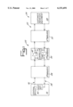
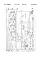
- FIG. 1 is a block diagram of a preferred embodiment of the present invention, as implemented in a line repeater interconnected to digital transmission lines;
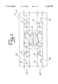
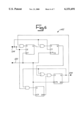
- FIG. 2 is a schematic diagram of the repeater shown in FIG. 1;
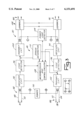
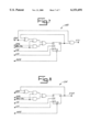
- FIG. 3 is a detailed block diagram of the repeater shown in FIG. 2;
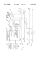
- FIG. 4 is a schematic diagram of the controller shown in FIG. 1;
- FIG. 5 is a schematic diagram of the error interface shown in FIG. 4;
- FIG. 6 is a schematic diagram of the error timing block used in the error interface shown in FIG. 5;
- FIG. 7 is a schematic diagram of the middle flip-flop circuits used in the error interface shown in FIG. 5;
- FIG. 8 is a schematic diagram of the end flip-flop circuit used in the error interface shown in FIG. 5.
- a preferred embodiment of the present invention is shown as a remote reporting system 20 for digital transmission lines 22.
- existing digital transmission facilities 24 include, in addition to the lines 22, a central office 26, a plurality of line repeaters (designated as a first line repeater 28, a second line repeater 30 and an "Nth" line repeater 32), an NIU 33, and customer premises equipment 34.
- the digital transmission lines 22 include first and second pairs of exchange grade transmission cables 36, 38 interconnecting the central office 26, line repeaters 28-32, NIU 33 and customer premises equipment 34.
- the central office 26 may include test equipment, such as a test set 40 (which may be, for example, a Hewlett Packard 37701A test set) applied between the first and second pairs of cables 36, 38.
- the test set 40 may apply signals to the cables 36, 38 to run diagnostic tests on the transmission facilities 24 to determine their integrity and to find faults in the system.
- the test set 40 may also be interconnected anywhere else between the two pairs of cables 36, 38 including, for example, at the customer premises equipment 34.
- the test set 40 is shown in the central office 26 in FIG. 1 for purposes of illustration.
- the repeater 30 includes first and second build-out circuits 42, 44 and a controller 46 interconnected between the two pairs of cables 36, 38.
- the repeater 30 receives an incoming data stream along the cables 36 and responsively provides a regenerated signal. During normal operation, the regenerated output from the build-out circuit 42 is transmitted further along the cables 36 to the other repeaters and ultimately to the customer premises equipment 34.
- the repeater 30 may be switched, for example, to a loop back mode, where the output of the build-out circuit 42 is redirected back toward the central office 26 along the cables 38 toward the test set 40.
- the test set 40 may apply a signal along the cables 36 to test the second repeater 30.
- a technician may determine that the lines 22, up to the point where the repeater 30 has "looped back" the test signal, are working correctly.
- the portion of the cables 36, upon which the build-out circuit 42 receives an incoming data stream is referred to as the incoming data transmission line.
- the portion of the cables upon which the output of the build-out circuit 42 is applied whether it be the rest of the cables 36 (between the repeater 30 and the NIU 31 at the customer premises equipment 34) or the cables 38 (between the repeater 30 and the central office 26) shall be referred to as the outgoing data transmission line, and the signal applied to this outgoing data transmission line shall be referred to as the repeated data stream.
- the second repeater 30 is shown in more detail in FIG. 2.
- the first pair of cables 36 is identified as first and second cables 48, 50; similarly, the second pair of cables 38 is identified as first and second cables 52, 54.
- the first build-out circuit 42 is interconnected to the cables 48, 50, and the second build-out circuit 44 is interconnected to the cables 52, 54.
- the repeater 30 also includes protection circuitry 56 to limit the damage to the repeater 30 and the transmission lines 22 should the lines 22 be struck by lighting or should power cross occur (where power cables are short-circuited against each other).
- overload protection circuitry 56 includes high wattage, current limiting resistors 58, 60, 62, 64, 66, 68, 70, 72 to limit the amount of current that will pass through a particular line when a high voltage is applied to it.
- varistors 74, 76, 78 80 are placed across the cables 48, 50, 52, 54 to again limit the current when a high voltage is accidentally applied.
- the repeater 30 divides the cables 48, 50 into first and second spans 82, 84, and the cables 52, 54 into first and second spans 86, 88.
- the controller 46 is interconnected all spans 82-88 of the cables 48-54.
- the controller 46 may include the "intelligence" of the repeater 30, that will allow the repeater 30 to respond to various conditions or signals that the repeater 30 receives, via the transmission lines or other methods.
- the transmission lines 22 may provide a signal such that the controller 46 will responsively place the repeater 30 in a logical or metallic loop back condition.
- the repeater 30 may identify itself according to a numerical code. Thus, for example, when called upon with a status inquiry to identify itself as the second repeater, it will identify itself with a burst of twenty errors.
- the "Nth" repeater 32 will provide a burst of "N" errors.
- Such errors are preferably created every third "one" data bit.
- the errors do not occur on a framing bit nor do the errors occur where the payload is a zero.
- Errors in the preferred embodiment consist solely of converting non-framing bit "ones" into “zeros", which creates bi-polar violation errors and logic errors. It is recognized, of course, that the present invention may also, or alternatively, employ other types of errors or error message configurations.
- the repeater 30 may, for example, provide a single burst of twenty-five errors.
- the first digit of the number of errors may represent the repeater's position with respect to the central office 26.
- the second digit (five) may then be preselected code corresponding to a particular type of loopback condition that the repeater 30 is in.
- a code of twenty in contrast, might indicate that the second repeater 30 is operating in a standard transmission mode.
- the repeater may send other error-based messages to report status of options or transmission impairments.
- the repeater 30 is shown as a microprocessor-based system having the controller 46, a power supply 90, receiver circuitry 92, 94, code detector circuitry 96, 98, transmit circuitry 100, 102, a power loop detector 104, and loopback circuitry 106.
- the controller 46 includes microprocessor and control circuitry (“microprocessor”) 108 and an error generator 110.
- the operation of the elements associated with the cables 36 are explained for purposes of illustration. While in a normal transmission mode, the payload is applied to the first span 82 and is sensed by the receiver circuitry 92. The receiver circuitry 92 forwards the signal to the code detector 96 which senses, for example, whether a particular loopback code exists in the incoming data stream. If not, the transmit circuitry 100 then regenerates the signal and applies it to the second span 84 of the cables 36.
- the power loop detector may sense an open transmission path on the spans between the second repeater 30 and the customer premises equipment 34. If this happens, the detector 104 signals the microprocessor 108, which, in turn, causes the loopback circuitry 106 to loopback all power and data signals.
- the code detector 96 may sense that the repeater 30 should change its condition by, for example, switching to a loopback mode.
- the detector 96 signals the microprocessor 108, and the microprocessor 108 then applies a signal to the loopback circuitry 106, such that data signals received from the first span 82 are then transmitted, via the loopback circuitry 106, to the receiver circuitry 94 and, ultimately, to the second span 88 of the cables 38.
- the code detector 96 also determines whether, for example, a test set 40 is requesting that the repeater 30 identify its status, such as the location of the repeater 30 (or other information regarding the repeater 30) or what operating mode (such as loopback, power loopback, or metallic loopback) the repeater 30 happens to be in. In such a case, the microprocessor 108 then applies a signal to the error generator 110,. advising the error generator 110 that a particular status inquiry has been detected by the code detector 96.
- the code detector 96 responsively causes the microprocessor 108 to provide an initiation signal to the error generator 110.
- the error generator 110 introduces an error message into the data stream received along, for example, the first span 82.
- the repeated stream of data produced by the repeater 30 on either the second span 84 of the cables 36 or the second span 88 of the cables 38) will include errors introduced to the data stream. The errors may then be detected and decoded at a remote location by the test set 40 in order to determine the response to the status inquiry previously made.
- the repeater 30 generates a single, responsive coded burst of errors upon receiving a status inquiry.
- the burst of errors may be repeated periodically, at predetermined time intervals, such as every twenty seconds. The periodic burst of errors continues until the query signal that caused the errors to be produced originally is removed. The detector consequently provides a stop signal to the microprocessor 108, which in turn, advises the error generator 110 to stop producing periodic bursts of errors.
- the error generator 110 includes error interface circuitry 112 and error control circuitry 114.
- the error control circuitry 114 is interconnected to the cables 36, 38.
- either of the code detectors 96, 98 may provide a signal to the microprocessor 108.
- the microprocessor 108 responsively provides an initiation signal to the error interface 112 which, in turn, provides signals to the error controller 114.
- the microprocessor 108 communicates to the error generator via five control lines 116, a load shift line 118, a clock line 120, a clock synchronization ("clock/193") line 122, and a data select line 124.
- the error controller 114 selectively introduces errors into the stream of data on the digital transmission lines 22.
- the error controller 114 shown in FIG. 4 includes an error introduction line 126, first and second NAND gates 128, 130, and four AND gates 132, 134, 136, 138. If an error is to be introduced along the cables 36, the data select line 124 is in a high state, and the error introduction line 126 is in a high state. Thus, two high inputs are provided to the NAND gate 128. Low signals are consequently supplied to the AND gates 132, 134. Accordingly, if high inputs are provided by the cables 48, 50 to the AND gates 132, 134, incorrect, low inputs will be provided by AND gates 132, 134 to the second span 84.
- a low signal along the first span 82 always results in a low signal being produced by the AND gates 132, 134. Accordingly, the error controller 114 only allows the introduction of errors to occur by converting "ones" into “zeros". “Zeros" are not converted into “ones.”
- the embodiment serves as an example only. In another embodiment, logic error and bi-polar violation error message responses could be generated by converting zeros into ones in a generalized solution.
- the NAND gate 130 allows errors to be introduced along the second span 88 of the second pair of cables 38.
- the clock signal from the microprocessor 108 keeps the error interface 112 providing information in synchronization with the repeated data stream that the transmit circuitry 100, 102 generates.
- the load shift line 118 provides a pulse to move the data through the error interface 112.
- the clock synchronization line 122 effectively provides a pulse every 193 clock pulses.
- the clock synchronization line 122 provides a positive pulse whenever the transmit circuitry 100, 102 is regenerating a framing bit. In such a case, the error interface 112 is inhibited from producing an error signal along any output line.
- the error interface 122 is shown in more detail in FIG. 5.
- the error interface 112 includes a synchronous binary up counter ("parallel counter") 140, logical output circuitry 142, a framing bit and data alignment circuit 144, and an error timing block 145.
- the synchronous binary up counter 140 includes a front flip-flop 146, three middle flip-flop circuits 148, 150, 152, and an end flip-flop circuit 154.
- the logical output circuitry 142 includes an AND gate 158 and a carry out line 160.
- the logical output circuitry 142 feeds the error line 126.
- the microprocessor 108 operates as a command generator to issue a command or initiation signal to the error interface 112.
- the command signal represents a predetermined number of errors that are to be introduced. The number is loaded in a parallel fashion from the microprocessor 108 into the parallel counter 140 via the control lines 116. If the error interface is to produce five errors, then the value of 26 (1AH, 11010 binary), which is 31-5, is loaded from the microprocessor 108. This allows the counter 140 to count up to 31.
- the alignment circuit 144 prevents the error interface 112 from producing an error signal in lieu of framing bit. For every 193rd bit (framing bit), the alignment circuit 144 disables the clock enable inputs in each of the flip-flop circuits 146-154. On every 193rd bit, all five outputs of the flip-flops circuits 146-154 provide a high, or "one,” output.
- the error timing block 145 controls when the binary up counter 140 is incremented, which preferably occurs on every third data bit that is a "one". See FIG. 6.
- FIG. 7 Specific circuitry used to implement the middle flip-flop circuit 148 is shown in FIG. 7. This is substantially the same circuit used for the other middle flip-flop circuits 150, 152 as well.
- the circuitry to construct the end flip-flop circuit 154 is shown in FIG. 8.
- the microprocessor 108 would first load the value of 21 into the counter 140, via the parallel load lines 116.
- the microprocessor 108 may delay a predetermined interval of time after receiving a signal from the code detector 98 (such as between four and eleven seconds) before sending the command signal to the error generator 110, to enable the error generator 110 to introduce errors into the repeated data stream.
- the flip-flop circuits 146-154 would continue counting up errors until all ten errors had been introduced into the transmission line 22.
- the error line 126 would then stay at a low level, such that the output of the NAND gates 128, 130 are always high. Consequently, the outputs of the NAND gates 132-138 are high or low, depending solely on whether the incoming data are high or low.
- the repeater 30 would function without the introducing of any additional errors into the repeated data stream.
- the microprocessor 108 may thereafter periodically issue the same command signal to the error generator (causing another burst of errors) until one of the code detectors 96, 98 detects the removal of the query signal. Thereafter, the microprocessor 108 stops periodically issuing the command signal, until it is advised that another status inquiry has been made.
- the NIU may send a predetermined set of error messages to remote test equipment in order to report status information of transmission impairments or option settings.
Landscapes
- Engineering & Computer Science (AREA)
- Computer Networks & Wireless Communication (AREA)
- Signal Processing (AREA)
- Detection And Prevention Of Errors In Transmission (AREA)
- Maintenance And Management Of Digital Transmission (AREA)
Abstract
Description
Claims (40)
Priority Applications (2)
| Application Number | Priority Date | Filing Date | Title |
|---|---|---|---|
| US09/229,532 US6151691A (en) | 1992-09-11 | 1999-01-13 | Remote reporting system for digital transmission line elements |
| US09/652,881 US6453432B1 (en) | 1992-09-11 | 2000-08-31 | Method and system for communicating the status of a digital transmission line element during loopback |
Applications Claiming Priority (3)
| Application Number | Priority Date | Filing Date | Title |
|---|---|---|---|
| US07/943,859 US5680405A (en) | 1992-09-11 | 1992-09-11 | Remote reporting system for digital transmission line elements |
| US08/951,121 US5889785A (en) | 1992-09-11 | 1997-10-16 | Remote reporting system for digital transmission line elements |
| US09/229,532 US6151691A (en) | 1992-09-11 | 1999-01-13 | Remote reporting system for digital transmission line elements |
Related Parent Applications (1)
| Application Number | Title | Priority Date | Filing Date |
|---|---|---|---|
| US08/951,121 Continuation US5889785A (en) | 1992-09-11 | 1997-10-16 | Remote reporting system for digital transmission line elements |
Related Child Applications (1)
| Application Number | Title | Priority Date | Filing Date |
|---|---|---|---|
| US09/652,881 Continuation US6453432B1 (en) | 1992-09-11 | 2000-08-31 | Method and system for communicating the status of a digital transmission line element during loopback |
Publications (1)
| Publication Number | Publication Date |
|---|---|
| US6151691A true US6151691A (en) | 2000-11-21 |
Family
ID=25480389
Family Applications (4)
| Application Number | Title | Priority Date | Filing Date |
|---|---|---|---|
| US07/943,859 Expired - Lifetime US5680405A (en) | 1992-09-11 | 1992-09-11 | Remote reporting system for digital transmission line elements |
| US08/951,121 Expired - Lifetime US5889785A (en) | 1992-09-11 | 1997-10-16 | Remote reporting system for digital transmission line elements |
| US09/229,532 Expired - Lifetime US6151691A (en) | 1992-09-11 | 1999-01-13 | Remote reporting system for digital transmission line elements |
| US09/652,881 Expired - Fee Related US6453432B1 (en) | 1992-09-11 | 2000-08-31 | Method and system for communicating the status of a digital transmission line element during loopback |
Family Applications Before (2)
| Application Number | Title | Priority Date | Filing Date |
|---|---|---|---|
| US07/943,859 Expired - Lifetime US5680405A (en) | 1992-09-11 | 1992-09-11 | Remote reporting system for digital transmission line elements |
| US08/951,121 Expired - Lifetime US5889785A (en) | 1992-09-11 | 1997-10-16 | Remote reporting system for digital transmission line elements |
Family Applications After (1)
| Application Number | Title | Priority Date | Filing Date |
|---|---|---|---|
| US09/652,881 Expired - Fee Related US6453432B1 (en) | 1992-09-11 | 2000-08-31 | Method and system for communicating the status of a digital transmission line element during loopback |
Country Status (1)
| Country | Link |
|---|---|
| US (4) | US5680405A (en) |
Cited By (4)
| Publication number | Priority date | Publication date | Assignee | Title |
|---|---|---|---|---|
| US6453432B1 (en) * | 1992-09-11 | 2002-09-17 | Westell Technologies, Inc. | Method and system for communicating the status of a digital transmission line element during loopback |
| US6829292B1 (en) * | 2000-01-03 | 2004-12-07 | Symmetricom, Inc. | Increasing gain with isolating upstream and downstream filters and amplifiers |
| US7092362B1 (en) * | 2000-08-01 | 2006-08-15 | Verizon Services Corp. | Terminal extension repeater |
| US20100149999A1 (en) * | 2008-12-12 | 2010-06-17 | Beattie Jr James Gordon | Methods and Apparatus to Pre-Qualify User Communities for Communication Services |
Families Citing this family (10)
| Publication number | Priority date | Publication date | Assignee | Title |
|---|---|---|---|---|
| US5907579A (en) * | 1996-12-20 | 1999-05-25 | Alcatel Network Systems, Inc. | Repeater bipolar violation in-service detection system |
| US6732191B1 (en) * | 1997-09-10 | 2004-05-04 | Schneider Automation Inc. | Web interface to an input/output device |
| US6956826B1 (en) * | 1999-07-07 | 2005-10-18 | Serconet Ltd. | Local area network for distributing data communication, sensing and control signals |
| US6560720B1 (en) * | 1999-09-09 | 2003-05-06 | International Business Machines Corporation | Error injection apparatus and method |
| US6690916B1 (en) * | 2000-10-10 | 2004-02-10 | Motorola, Inc. | Radio network for radio communication in an enclosed environment and a repeater for such a radio network |
| US7609817B1 (en) | 2005-07-05 | 2009-10-27 | Adtran, Inc. | Termination circuit for network interface unit |
| US7406545B1 (en) * | 2005-10-20 | 2008-07-29 | Western Digital Technologies, Inc. | Disk drive or any serial attached device logging a cable loss event |
| US20070295871A1 (en) * | 2006-06-22 | 2007-12-27 | Adc Telecommunications, Inc. | Strand mount hook |
| US10340864B2 (en) * | 2012-05-04 | 2019-07-02 | Infineon Technologies Ag | Transmitter circuit and method for controlling operation thereof |
| CN112868193B (en) * | 2018-10-04 | 2023-07-14 | 维尔塞特公司 | Time Division Duplex (TDD) antenna system |
Citations (12)
| Publication number | Priority date | Publication date | Assignee | Title |
|---|---|---|---|---|
| US4425662A (en) * | 1980-03-18 | 1984-01-10 | Telecommunications Radioelectriques Et Telephoniques T.R.T. | System for tele-locating regenerative repeaters |
| US4545013A (en) * | 1979-01-29 | 1985-10-01 | Infinet Inc. | Enhanced communications network testing and control system |
| US4630268A (en) * | 1984-08-30 | 1986-12-16 | Rockwell International Corporation | Communication circuit loopback test apparatus |
| US4635260A (en) * | 1983-05-18 | 1987-01-06 | Telefonia Elettronica E Radio S.P.A. | Data transmission telemonitoring equipment and system |
| US4813044A (en) * | 1987-01-30 | 1989-03-14 | International Business Machines Corporation | Method and apparatus for detecting transient errors |
| US4937825A (en) * | 1988-06-15 | 1990-06-26 | International Business Machines | Method and apparatus for diagnosing problems in data communication networks |
| US4980887A (en) * | 1988-10-27 | 1990-12-25 | Seiscor Technologies | Digital communication apparatus and method |
| US5216697A (en) * | 1989-08-19 | 1993-06-01 | Fujitsu Limited | Signal quality detector circuit |
| US5224149A (en) * | 1992-02-26 | 1993-06-29 | Teltrend, Inc. | Testing system for digital transmission lines |
| US5317278A (en) * | 1990-07-23 | 1994-05-31 | Rc Concepts, Inc. | Switched active fault locate filter |
| US5555274A (en) * | 1992-03-02 | 1996-09-10 | Teltrend Inc. | Phantom data link for digital transmission lines |
| US5680405A (en) * | 1992-09-11 | 1997-10-21 | Teltrend Incorporated | Remote reporting system for digital transmission line elements |
Family Cites Families (8)
| Publication number | Priority date | Publication date | Assignee | Title |
|---|---|---|---|---|
| FR1565552A (en) * | 1968-03-08 | 1969-05-02 | ||
| US3950622A (en) * | 1974-10-15 | 1976-04-13 | Culbertson Industries Inc. | Line fault locating system |
| IT1040148B (en) * | 1975-07-28 | 1979-12-20 | Sits Soc It Telecom Siemens | REMOTE SURVEILLANCE SYSTEM FOR PCM TRANSMISSION SYSTEMS |
| US4112263A (en) * | 1977-04-06 | 1978-09-05 | Gte Automatic Electric Laboratories Incorporated | Modified duobinary regenerative repeater testing arrangement |
| FR2395650A1 (en) * | 1977-06-20 | 1979-01-19 | France Etat | REMOTE LOCATION SYSTEM ON AN ANALOG OR DIGITAL TRANSMISSION LINK INCLUDING IN PARTICULAR REPEATERS-REGENERATORS |
| US4278850A (en) * | 1978-04-11 | 1981-07-14 | Kokusai Denshin Denwa Co., Ltd. | Monitoring system for optical transmission line repeaters |
| JPS5515064A (en) * | 1978-07-19 | 1980-02-01 | Doryokuro Kakunenryo | Method of cooling emergently pressure tube type nuclear reactor |
| JPS55150643A (en) * | 1979-05-15 | 1980-11-22 | Kokusai Denshin Denwa Co Ltd <Kdd> | Trouble-shoot system of digital transmission system |
-
1992
- 1992-09-11 US US07/943,859 patent/US5680405A/en not_active Expired - Lifetime
-
1997
- 1997-10-16 US US08/951,121 patent/US5889785A/en not_active Expired - Lifetime
-
1999
- 1999-01-13 US US09/229,532 patent/US6151691A/en not_active Expired - Lifetime
-
2000
- 2000-08-31 US US09/652,881 patent/US6453432B1/en not_active Expired - Fee Related
Patent Citations (13)
| Publication number | Priority date | Publication date | Assignee | Title |
|---|---|---|---|---|
| US4545013A (en) * | 1979-01-29 | 1985-10-01 | Infinet Inc. | Enhanced communications network testing and control system |
| US4425662A (en) * | 1980-03-18 | 1984-01-10 | Telecommunications Radioelectriques Et Telephoniques T.R.T. | System for tele-locating regenerative repeaters |
| US4635260A (en) * | 1983-05-18 | 1987-01-06 | Telefonia Elettronica E Radio S.P.A. | Data transmission telemonitoring equipment and system |
| US4630268A (en) * | 1984-08-30 | 1986-12-16 | Rockwell International Corporation | Communication circuit loopback test apparatus |
| US4813044A (en) * | 1987-01-30 | 1989-03-14 | International Business Machines Corporation | Method and apparatus for detecting transient errors |
| US4937825A (en) * | 1988-06-15 | 1990-06-26 | International Business Machines | Method and apparatus for diagnosing problems in data communication networks |
| US4980887A (en) * | 1988-10-27 | 1990-12-25 | Seiscor Technologies | Digital communication apparatus and method |
| US5216697A (en) * | 1989-08-19 | 1993-06-01 | Fujitsu Limited | Signal quality detector circuit |
| US5317278A (en) * | 1990-07-23 | 1994-05-31 | Rc Concepts, Inc. | Switched active fault locate filter |
| US5224149A (en) * | 1992-02-26 | 1993-06-29 | Teltrend, Inc. | Testing system for digital transmission lines |
| US5555274A (en) * | 1992-03-02 | 1996-09-10 | Teltrend Inc. | Phantom data link for digital transmission lines |
| US5680405A (en) * | 1992-09-11 | 1997-10-21 | Teltrend Incorporated | Remote reporting system for digital transmission line elements |
| US5889785A (en) * | 1992-09-11 | 1999-03-30 | Teltrend Inc. | Remote reporting system for digital transmission line elements |
Non-Patent Citations (2)
| Title |
|---|
| "3150-56 T1 Line Repeater with Addressable Loopback Plus," General Description, Installation & Maintenance Practice, Section 3150-56-100 Issue A, © Westell, Inc. Jul. 1992, printed in USA Oct. 1992. |
| 3150 56 T1 Line Repeater with Addressable Loopback Plus, General Description, Installation & Maintenance Practice, Section 3150 56 100 Issue A, Westell, Inc. Jul. 1992, printed in USA Oct. 1992. * |
Cited By (7)
| Publication number | Priority date | Publication date | Assignee | Title |
|---|---|---|---|---|
| US6453432B1 (en) * | 1992-09-11 | 2002-09-17 | Westell Technologies, Inc. | Method and system for communicating the status of a digital transmission line element during loopback |
| US6829292B1 (en) * | 2000-01-03 | 2004-12-07 | Symmetricom, Inc. | Increasing gain with isolating upstream and downstream filters and amplifiers |
| US7092362B1 (en) * | 2000-08-01 | 2006-08-15 | Verizon Services Corp. | Terminal extension repeater |
| US20100149999A1 (en) * | 2008-12-12 | 2010-06-17 | Beattie Jr James Gordon | Methods and Apparatus to Pre-Qualify User Communities for Communication Services |
| US8345560B2 (en) * | 2008-12-12 | 2013-01-01 | At&T Intellectual Property I, Lp | Methods and apparatus to pre-qualify user communities for communication services |
| US20130094631A1 (en) * | 2008-12-12 | 2013-04-18 | At&T Intellectual Property I, Lp | Methods and apparatus to pre-qualify user communities for communication services |
| US9100472B2 (en) * | 2008-12-12 | 2015-08-04 | At&T Intellectual Property I., L.P. | Methods and apparatus to pre-qualify user communities for communication services |
Also Published As
| Publication number | Publication date |
|---|---|
| US6453432B1 (en) | 2002-09-17 |
| US5680405A (en) | 1997-10-21 |
| US5889785A (en) | 1999-03-30 |
Similar Documents
| Publication | Publication Date | Title |
|---|---|---|
| US6151691A (en) | Remote reporting system for digital transmission line elements | |
| US4402075A (en) | Step-by-step remote locating system for repeaters in a PCM link | |
| US5224149A (en) | Testing system for digital transmission lines | |
| CA1186378A (en) | Local orderwire facility for fiber optic communication system | |
| US4397020A (en) | Error monitoring in digital transmission systems | |
| US5343461A (en) | Full duplex digital transmission facility loop-back test, diagnostics and maintenance system | |
| USRE33900E (en) | Error monitoring in digital transmission systems | |
| US4980887A (en) | Digital communication apparatus and method | |
| US4351059A (en) | Method for testing a digital data transmission line between two modems and a device for the application of said method | |
| WO1995015630A1 (en) | Network interface unit remote test pattern generation | |
| US4069402A (en) | Remote-testing arrangement for PCM transmission system | |
| US4064459A (en) | Method of automatically testing the serviceability of a data transmission system | |
| US4885743A (en) | Method and apparatus for detecting the collision of data packets | |
| US4257033A (en) | Fault locating system in optical fiber transmission system | |
| CA1270539A (en) | Fault location system for a digital transmission line | |
| US3965294A (en) | Method of and apparatus for testing transmission line carrying bipolar PCM signals | |
| US5347576A (en) | Line interface unit retrofit circuit | |
| US4455644A (en) | Telecommunication fault detecting system | |
| US5689546A (en) | Performance monitoring system for T1 telephone lines | |
| EP0021544A1 (en) | System for the remote testing of a modem for a speed of transmission different from the speed of reception | |
| US3649777A (en) | Supervisory apparatus for pcm regenerative repeaters | |
| EP0203151B1 (en) | Loop around data channel unit | |
| JPH0687552B2 (en) | Individual monitoring method and device for at least two consecutive transmission sub-sections in a transmission section for transmitting digital use signals | |
| US4740964A (en) | Alarm indications signal detection apparatus | |
| US5437023A (en) | Noise-tolerant address transmission system for digital telecommunication network |
Legal Events
| Date | Code | Title | Description |
|---|---|---|---|
| STCF | Information on status: patent grant |
Free format text: PATENTED CASE |
|
| AS | Assignment |
Owner name: LASALLE BANK NATIONAL ASSOCIATION (AS AGENT), ILLI Free format text: SECURITY AGREEMENT;ASSIGNOR:TELTREND, INC., A CORPORATION OF DELAWARE;REEL/FRAME:011245/0698 Effective date: 20000831 |
|
| AS | Assignment |
Owner name: WESTELL TECHNOLOGIES, INC., ILLINOIS Free format text: ASSIGNMENT OF ASSIGNORS INTEREST;ASSIGNOR:TELTREND INC.;REEL/FRAME:013011/0292 Effective date: 20020611 |
|
| FEPP | Fee payment procedure |
Free format text: PAYOR NUMBER ASSIGNED (ORIGINAL EVENT CODE: ASPN); ENTITY STATUS OF PATENT OWNER: LARGE ENTITY |
|
| REMI | Maintenance fee reminder mailed | ||
| FPAY | Fee payment |
Year of fee payment: 4 |
|
| SULP | Surcharge for late payment | ||
| AS | Assignment |
Owner name: LASALLE BANK NATIONAL ASSOCIATION, ILLINOIS Free format text: SECURITY AGREEMENT;ASSIGNOR:WESTELL TECHNOLOGIES, INC.;REEL/FRAME:017982/0876 Effective date: 20060630 |
|
| FPAY | Fee payment |
Year of fee payment: 8 |
|
| AS | Assignment |
Owner name: THE PRIVATEBANK AND TRUST COMPANY, ILLINOIS Free format text: SECURITY AGREEMENT;ASSIGNOR:WESTELL TECHNOLOGIES, INC.;REEL/FRAME:022597/0926 Effective date: 20090305 |
|
| AS | Assignment |
Owner name: TELTREND, INC., ILLINOIS Free format text: ASSIGNMENT OF ASSIGNORS INTEREST;ASSIGNORS:PESETSKI, PETER W.;ARNONE, NICHOLAS J.;REEL/FRAME:022746/0237;SIGNING DATES FROM 19920828 TO 19920908 |
|
| FPAY | Fee payment |
Year of fee payment: 12 |