US6151466A - Fixing device including vented chamber-like area - Google Patents
Fixing device including vented chamber-like area Download PDFInfo
- Publication number
- US6151466A US6151466A US09/379,838 US37983899A US6151466A US 6151466 A US6151466 A US 6151466A US 37983899 A US37983899 A US 37983899A US 6151466 A US6151466 A US 6151466A
- Authority
- US
- United States
- Prior art keywords
- fixing device
- cover
- gap
- fixing
- recording sheet
- Prior art date
- Legal status (The legal status is an assumption and is not a legal conclusion. Google has not performed a legal analysis and makes no representation as to the accuracy of the status listed.)
- Expired - Lifetime
Links
Images

Classifications
-
- G—PHYSICS
- G03—PHOTOGRAPHY; CINEMATOGRAPHY; ANALOGOUS TECHNIQUES USING WAVES OTHER THAN OPTICAL WAVES; ELECTROGRAPHY; HOLOGRAPHY
- G03G—ELECTROGRAPHY; ELECTROPHOTOGRAPHY; MAGNETOGRAPHY
- G03G15/00—Apparatus for electrographic processes using a charge pattern
- G03G15/20—Apparatus for electrographic processes using a charge pattern for fixing, e.g. by using heat
- G03G15/2003—Apparatus for electrographic processes using a charge pattern for fixing, e.g. by using heat using heat
- G03G15/2014—Apparatus for electrographic processes using a charge pattern for fixing, e.g. by using heat using heat using contact heat
- G03G15/2017—Structural details of the fixing unit in general, e.g. cooling means, heat shielding means
-
- G—PHYSICS
- G03—PHOTOGRAPHY; CINEMATOGRAPHY; ANALOGOUS TECHNIQUES USING WAVES OTHER THAN OPTICAL WAVES; ELECTROGRAPHY; HOLOGRAPHY
- G03G—ELECTROGRAPHY; ELECTROPHOTOGRAPHY; MAGNETOGRAPHY
- G03G2215/00—Apparatus for electrophotographic processes
- G03G2215/20—Details of the fixing device or porcess
- G03G2215/2003—Structural features of the fixing device
Definitions
- the present application relates to a fixing device for use in an electrophotographic copying machine, a printer, a facsimile machine, or the like. More particularly, the present application relates to a fixing device capable of preventing undesirable effects on devices located around the fixing device.
- Image forming apparatuses such as copying machines, facsimile machines, and printers, are provided with a fixing device to fix a toner image to a recording sheet.
- a fixing device includes a heat roller having a fixing heater inside thereof and a pressure roller rotatably contacting the heat roller with pressure.
- the fixing device is configured to fix a toner image onto a recording sheet by application of heat generated by the fixing heater to the recording sheet while nipping and conveying the recording sheet with the heat roller and the pressure roller. Therefore, a temperature of devices located in the vicinity of the fixing device rises due to heat irradiated from the fixing device. As a result, for example, condensation of moisture occurs on cold parts of a main body of the copying machine. In addition, recording sheets tend to curl when heated by the radiated heat. In addition, when a drive motor is mounted adjacent the fixing device, undesirable effects on the drive motor may occur.
- a fixing device is disposed adjacent to a toner reclaim tank which has a cleaning blade that contacts a photoconductor drum. Accordingly, when the temperature of the fixing device rises, the heat irradiated from the fixing device is transmitted to the toner reclaim tank and also to the cleaning blade. As a result, residual toner, which is contained in the toner reclaim tank, coagulates and residual toner which has adhered to an edge of the cleaning blade also coagulates. When the residual toner in the tank coagulates, it is hard for the toner reclaim tank to be fully filled with the residual toner. In addition, the coagulation of adhered toner at the cleaning blade results in deterioration in the cleaning properties of the blade, resulting in deterioration of image quality.
- Japanese Laid-Open Patent Publication Tokukaihei 5-134571 describes a fixing device in which a partition member is disposed between a fixing device cover and cleaning/toner magazines to insulate the cleaning/toner magazines from heat irradiated from the fixing device cover.
- the temperature of the partition member rises relatively high because the partition member is located adjacent to the fixing device cover. Therefore, if an operator inadvertently touches the partition member by hand when removing a recording sheet jammed around the fixing device or when exchanging a photoconductor unit which is located close to the fixing device, for example, the operator may possibly be injured by the heated partition member.
- the temperature of the devices located around the fixing device is kept high for a long period of time even after power to the apparatus is turned off. Accordingly, the operator must wait a long period of time for the devices around the fixing device to cool off prior to removing the jammed recording sheet or exchanging the photoconductor unit.
- the present invention has been made in view of the above-discussed problems and an object of the invention is to address and resolve these and other problems.
- a preferred embodiment of the present invention provides a novel fixing device capable of preventing heat generated by a fixing heater from being transmitted to a fixing device cover and preventing air at high temperature in the fixing device cover from remaining in the cover.
- a novel fixing device includes a fixing member that fixes a toner image to a recording sheet by heat, a cover to accommodate the fixing member, at least one partition member provided inside the cover so as to form a gap between the partition member and an internal circumferential surface of the cover, and an opening formed at a part of the cover above the gap.
- the novel fixing device may further include an exhausting fan to exhaust air in the gap outside of the cover through the opening.
- the exhausting fan may be provided outside of the cover, and a duct may be provided between the opening and the exhausting fan.
- FIG. 1 is a schematic illustration of a copying machine having a fixing device according to the present invention
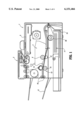
- FIG. 2 is a schematic illustration of the fixing device according to the present invention.
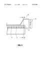
- FIG. 3 is a schematic illustration of the vicinity of openings of the fixing device.
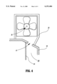
- FIG. 4 is a cross-sectional view taken along line 4--4 in FIG. 3.
- FIGS. 1 to 4 are illustrations of a fixing device according to an embodiment of the present invention, in which the fixing device is applied to a copying machine.
- the fixing device can also be applied to other types of image forming apparatuses, such as, for example, facsimile machines and printers.
- a configuration of the copying machine is first explained referring to FIG. 1.
- a copying machine 1 includes an automatic document feeder 2 mounted thereon.
- the automatic document feeder 2 conveys a document to a reading section 3.
- reading section 3 reads an image of a document and irradiates a photoconductor drum 6 with light modulated according to read image information via a polygon mirror 4 and a reflecting mirror 5.
- a surface of the photoconductor drum 6 is first charged by a charging device (not shown) and an electrostatic latent image is formed on the charged surface of the photoconductor drum 6 by the light from the reading section 3.
- a developing device 7 disposed around the photoconductor drum 6 includes a toner tank 8 and a toner reclaim tank 9 which are formed in a body. Toner that is contained in the toner tank 8 is supplied to the photoconductor drum 6 with a roller member 8a to develop the electrostatic latent image formed on the photoconductor drum 6.
- the recording sheet 11 is conveyed to a nip portion between the photoconductor drum 6 and a transfer roller 12 and a toner image on the photoconductor drum 6 is transferred onto the recording sheet 11 by application of a voltage to the transfer roller 12 by a power pack (not shown).
- the toner reclaim tank 9 has a toner reclaim blade and a toner reclaim roller (not shown). A residual toner that adheres to the photoconductor drum 6 is reclaimed in the toner reclaim tank 9 by the toner reclaim blade and the toner reclaim roller.
- a fixing device 13 is provided adjacent the toner reclaim tank 9 and close to the photoconductor drum 6.
- the fixing device 13 includes a fixing member composed of a heat roller 14 having a fixing heater inside thereof and a pressing roller 15 rotatably contacting the heat roller 14 with pressure.
- the fixing device 13 is configured to fix a toner image on a recording sheet 11 by application of heat to the toner image while nipping and conveying the recording sheet 11 between the heat roller 14 and the pressing roller 15.
- the recording sheet 11 is discharged to a sheet-discharging tray 17 by a pair of sheet-discharging rollers 16 after the toner image has been fixed onto the recording sheet 11.
- the heat roller 14 and the pressing roller 15 are accommodated in a molded fixing device cover 18, and a partition member 19 made of sheet metal is disposed inside the fixing device cover 18.
- the partition member 19 may be made of a material other than metal.
- the partition member 19 is disposed so as to form a gap 20 between the partition member 19 and an internal surface of the fixing device cover 18 that opposes the toner reclaim tank 9.
- the gap 20 forms a chamber-like area between the partition member 19 and the internal surface of the fixing device cover 18.
- a plurality of openings 21 are formed in the fixing device cover 18 above the gap 20.
- an exhausting fan 22 is provided outside of the fixing device cover 18 and the exhausting fan 22 and the openings 21 communicate with each other by a duct 23.
- the exhausting fan 22 is mounted on a main body cover of the copying machine 1.
- the exhausting fan 22 may be mounted at positions other than on the main body cover in the main body of the copying machine 1, preferably in positions where the heat from the fixing device 13 will not affect the fan much.
- the partition member 19 is disposed so as to form the gap 20 between the partition member 19 and the internal surface of the fixing device cover 18 that opposes the toner reclaim tank 9 and the plurality of openings 21 are formed in the fixing device cover 18 above the gap 20.
- the fan rotates in a direction to pull hot air from inside gap 20 through openings 21 and duct 23. Accordingly, the heat generated by the fixing heater can be prevented from being transmitted to the fixing device cover 18 by the partition member 19. Furthermore, the high temperature air in the fixing device cover 18 is exhausted through the openings 21 and does not remain in the fixing device cover 18. As a result, the temperature of the fixing device cover 18 can be prevented from rising too high. Therefore, a removing operation for removing a recording sheet, which is jammed in the fixing device 13, and an exchanging operation for exchanging a photoconductor drum unit located near the fixing device 13, can be easily performed by the operator.
- the heat generated by the fixing heater does not reach the toner reclaim tank 9 where the residual toner is contained. Therefore, the coagulation of the residual toner adhering to an edge of a cleaning blade of the toner reclaim tank 9, which results in deterioration of image quality due to deterioration of cleaning properties of the photoconductor drum, can be prevented.
- the air in the gap 20 can be positively exhausted outward by the exhausting fan 22 through the opening 21, the relatively high temperature air can be prevented from remaining in the fixing device cover 18 and the heat remaining in the fixing device cover 18 can be effectively removed.
- the temperature of the fixing device 13 can be prevented from rising too high and the heat can be prevented from being transmitted to the toner reclaim tank 9 more effectively.
- the exhausting fan 22 and the openings 21 communicate with each other by the duct 23, the high temperature air that passes through the openings 21 is prevented from being scattered inside the main body of the copying machine 1 and is effectively exhausted outside of the fixing device cover 18. Thereby, the temperature of the fixing device 13 can be prevented from rising high and the heat generated by the fixing heater can be further prevented from being transmitted to the toner reclaim tank 9.
- partition member 19 when a plurality of devices in the main body of the copying machine, such as, for example, a transfer device, a charging device, and the like, are disposed adjacent to the fixing device 13 in addition to the toner reclaim tank 9, the heat generated by the fixing heater can be prevented from being transmitted to these devices by disposing a plurality of partition members in the fixing device 13 at positions opposed to the plurality of devices, respectively.
Landscapes
- Physics & Mathematics (AREA)
- General Physics & Mathematics (AREA)
- Fixing For Electrophotography (AREA)
- Control Or Security For Electrophotography (AREA)
- Electrophotography Configuration And Component (AREA)
- Accessory Devices And Overall Control Thereof (AREA)
Abstract
A fixing device includes a fixing member that fixes a toner image to a recording sheet by heat, a cover to accommodate the fixing member, at least one partition member provided inside the cover so as to form a gap between the partition member and an internal circumferential surface of the cover, and an opening formed at a part of the cover above the gap.
Description
1. Field of the Invention
The present application relates to a fixing device for use in an electrophotographic copying machine, a printer, a facsimile machine, or the like. More particularly, the present application relates to a fixing device capable of preventing undesirable effects on devices located around the fixing device.
2. Discussion of the Background
Image forming apparatuses, such as copying machines, facsimile machines, and printers, are provided with a fixing device to fix a toner image to a recording sheet. Generally, such a fixing device includes a heat roller having a fixing heater inside thereof and a pressure roller rotatably contacting the heat roller with pressure. The fixing device is configured to fix a toner image onto a recording sheet by application of heat generated by the fixing heater to the recording sheet while nipping and conveying the recording sheet with the heat roller and the pressure roller. Therefore, a temperature of devices located in the vicinity of the fixing device rises due to heat irradiated from the fixing device. As a result, for example, condensation of moisture occurs on cold parts of a main body of the copying machine. In addition, recording sheets tend to curl when heated by the radiated heat. In addition, when a drive motor is mounted adjacent the fixing device, undesirable effects on the drive motor may occur.
In recent years, because of the trend toward space-saving and compact-sizing of image forming apparatuses, the size of each device forming the image forming apparatus has become smaller and a distance between respective devices has tended to become shorter. Therefore, devices near the fixing device more easily receive the heat irradiated from the fixing device.
Generally, a fixing device is disposed adjacent to a toner reclaim tank which has a cleaning blade that contacts a photoconductor drum. Accordingly, when the temperature of the fixing device rises, the heat irradiated from the fixing device is transmitted to the toner reclaim tank and also to the cleaning blade. As a result, residual toner, which is contained in the toner reclaim tank, coagulates and residual toner which has adhered to an edge of the cleaning blade also coagulates. When the residual toner in the tank coagulates, it is hard for the toner reclaim tank to be fully filled with the residual toner. In addition, the coagulation of adhered toner at the cleaning blade results in deterioration in the cleaning properties of the blade, resulting in deterioration of image quality.
Japanese Laid-Open Patent Publication Tokukaihei 5-134571 describes a fixing device in which a partition member is disposed between a fixing device cover and cleaning/toner magazines to insulate the cleaning/toner magazines from heat irradiated from the fixing device cover.
However, in such a background fixing device, the temperature of the partition member rises relatively high because the partition member is located adjacent to the fixing device cover. Therefore, if an operator inadvertently touches the partition member by hand when removing a recording sheet jammed around the fixing device or when exchanging a photoconductor unit which is located close to the fixing device, for example, the operator may possibly be injured by the heated partition member.
In addition, because air which is heated by the heat generated by the fixing device remains in a small space in the fixing device cover, the temperature of the devices located around the fixing device is kept high for a long period of time even after power to the apparatus is turned off. Accordingly, the operator must wait a long period of time for the devices around the fixing device to cool off prior to removing the jammed recording sheet or exchanging the photoconductor unit.
The present invention has been made in view of the above-discussed problems and an object of the invention is to address and resolve these and other problems.
A preferred embodiment of the present invention provides a novel fixing device capable of preventing heat generated by a fixing heater from being transmitted to a fixing device cover and preventing air at high temperature in the fixing device cover from remaining in the cover.
A novel fixing device according to an embodiment of the present invention includes a fixing member that fixes a toner image to a recording sheet by heat, a cover to accommodate the fixing member, at least one partition member provided inside the cover so as to form a gap between the partition member and an internal circumferential surface of the cover, and an opening formed at a part of the cover above the gap.
The novel fixing device may further include an exhausting fan to exhaust air in the gap outside of the cover through the opening.
The exhausting fan may be provided outside of the cover, and a duct may be provided between the opening and the exhausting fan.
A more complete appreciation of the present invention and many of the attendant advantages thereof will be readily obtained as the same becomes better understood by reference to the following detailed description when considered in conjunction with the accompanying drawings, wherein:
FIG. 1 is a schematic illustration of a copying machine having a fixing device according to the present invention;
FIG. 2 is a schematic illustration of the fixing device according to the present invention;
FIG. 3 is a schematic illustration of the vicinity of openings of the fixing device; and
FIG. 4 is a cross-sectional view taken along line 4--4 in FIG. 3.
The preferred embodiments of the present invention are now described in detail referring to the drawings, wherein like reference numerals indicate identical or corresponding parts throughout the several views.
FIGS. 1 to 4 are illustrations of a fixing device according to an embodiment of the present invention, in which the fixing device is applied to a copying machine. Of course, the fixing device can also be applied to other types of image forming apparatuses, such as, for example, facsimile machines and printers.
A configuration of the copying machine is first explained referring to FIG. 1. A copying machine 1 includes an automatic document feeder 2 mounted thereon. The automatic document feeder 2 conveys a document to a reading section 3. As shown in FIG. 2, reading section 3 reads an image of a document and irradiates a photoconductor drum 6 with light modulated according to read image information via a polygon mirror 4 and a reflecting mirror 5.
A surface of the photoconductor drum 6 is first charged by a charging device (not shown) and an electrostatic latent image is formed on the charged surface of the photoconductor drum 6 by the light from the reading section 3.
A developing device 7 disposed around the photoconductor drum 6 includes a toner tank 8 and a toner reclaim tank 9 which are formed in a body. Toner that is contained in the toner tank 8 is supplied to the photoconductor drum 6 with a roller member 8a to develop the electrostatic latent image formed on the photoconductor drum 6.
Referring again to FIG. 1, a recording sheet 11, which is contained in a sheet-feeding cassette 10, is supplied toward the photoconductor drum 6 by a sheet-feeding roller 30. The recording sheet 11 is conveyed to a nip portion between the photoconductor drum 6 and a transfer roller 12 and a toner image on the photoconductor drum 6 is transferred onto the recording sheet 11 by application of a voltage to the transfer roller 12 by a power pack (not shown). The toner reclaim tank 9 has a toner reclaim blade and a toner reclaim roller (not shown). A residual toner that adheres to the photoconductor drum 6 is reclaimed in the toner reclaim tank 9 by the toner reclaim blade and the toner reclaim roller.
A fixing device 13 is provided adjacent the toner reclaim tank 9 and close to the photoconductor drum 6. The fixing device 13 includes a fixing member composed of a heat roller 14 having a fixing heater inside thereof and a pressing roller 15 rotatably contacting the heat roller 14 with pressure. The fixing device 13 is configured to fix a toner image on a recording sheet 11 by application of heat to the toner image while nipping and conveying the recording sheet 11 between the heat roller 14 and the pressing roller 15. The recording sheet 11 is discharged to a sheet-discharging tray 17 by a pair of sheet-discharging rollers 16 after the toner image has been fixed onto the recording sheet 11.
As illustrated in FIG. 2, the heat roller 14 and the pressing roller 15 are accommodated in a molded fixing device cover 18, and a partition member 19 made of sheet metal is disposed inside the fixing device cover 18. The partition member 19 may be made of a material other than metal.
The partition member 19 is disposed so as to form a gap 20 between the partition member 19 and an internal surface of the fixing device cover 18 that opposes the toner reclaim tank 9. The gap 20 forms a chamber-like area between the partition member 19 and the internal surface of the fixing device cover 18. A plurality of openings 21 are formed in the fixing device cover 18 above the gap 20. Furthermore, as illustrated in FIGS. 3 and 4, an exhausting fan 22 is provided outside of the fixing device cover 18 and the exhausting fan 22 and the openings 21 communicate with each other by a duct 23. The exhausting fan 22 is mounted on a main body cover of the copying machine 1. The exhausting fan 22 may be mounted at positions other than on the main body cover in the main body of the copying machine 1, preferably in positions where the heat from the fixing device 13 will not affect the fan much.
In the above embodiment of the present invention, the partition member 19 is disposed so as to form the gap 20 between the partition member 19 and the internal surface of the fixing device cover 18 that opposes the toner reclaim tank 9 and the plurality of openings 21 are formed in the fixing device cover 18 above the gap 20. The fan rotates in a direction to pull hot air from inside gap 20 through openings 21 and duct 23. Accordingly, the heat generated by the fixing heater can be prevented from being transmitted to the fixing device cover 18 by the partition member 19. Furthermore, the high temperature air in the fixing device cover 18 is exhausted through the openings 21 and does not remain in the fixing device cover 18. As a result, the temperature of the fixing device cover 18 can be prevented from rising too high. Therefore, a removing operation for removing a recording sheet, which is jammed in the fixing device 13, and an exchanging operation for exchanging a photoconductor drum unit located near the fixing device 13, can be easily performed by the operator.
In addition, the heat generated by the fixing heater does not reach the toner reclaim tank 9 where the residual toner is contained. Therefore, the coagulation of the residual toner adhering to an edge of a cleaning blade of the toner reclaim tank 9, which results in deterioration of image quality due to deterioration of cleaning properties of the photoconductor drum, can be prevented.
Furthermore, because the air in the gap 20 can be positively exhausted outward by the exhausting fan 22 through the opening 21, the relatively high temperature air can be prevented from remaining in the fixing device cover 18 and the heat remaining in the fixing device cover 18 can be effectively removed. As a result, the temperature of the fixing device 13 can be prevented from rising too high and the heat can be prevented from being transmitted to the toner reclaim tank 9 more effectively.
Furthermore, because the exhausting fan 22 and the openings 21 communicate with each other by the duct 23, the high temperature air that passes through the openings 21 is prevented from being scattered inside the main body of the copying machine 1 and is effectively exhausted outside of the fixing device cover 18. Thereby, the temperature of the fixing device 13 can be prevented from rising high and the heat generated by the fixing heater can be further prevented from being transmitted to the toner reclaim tank 9.
Although only one partition member 19 is provided in this embodiment, when a plurality of devices in the main body of the copying machine, such as, for example, a transfer device, a charging device, and the like, are disposed adjacent to the fixing device 13 in addition to the toner reclaim tank 9, the heat generated by the fixing heater can be prevented from being transmitted to these devices by disposing a plurality of partition members in the fixing device 13 at positions opposed to the plurality of devices, respectively.
Numerous modifications and variations of the present invention are possible in light of the above teachings. It is therefore to be understood that within the scope of the appended claims, the invention may be practiced otherwise than as specifically described herein.
This document claims priority and contains subject matter related to Japanese Patent Application No. 10-236668, filed on Aug. 24, 1998, and the entire contents thereof are herein incorporated by reference.
Claims (9)
1. A fixing device to fix a toner image to a recording sheet, comprising:
a fixing member that fixes the toner image to the recording sheet by heat;
a cover to accommodate the fixing member;
at least one partition member provided inside the cover to provide a gap which forms a chamber-like area between the at least one partition member and an internal circumferential surface of the cover; and
at least one opening formed at a part of the cover above the gap within the chamber-like area.
2. The fixing device according to claim 1, further comprising:
an exhausting fan to exhaust air in the gap outside of the cover through the at least one opening.
3. The fixing device according to claim 2, wherein the exhausting fan is provided outside of the cover and a duct is provided between the at least one opening and the exhausting fan.
4. A fixing device to fix a toner image to a recording sheet, comprising:
means for fixing the toner image to the recording sheet by heat;
means for accommodating the fixing means;
means for partitioning the accommodating means to provide a gap which forms a chamber-like area between the partitioning means and an internal circumferential surface of the accommodating means; and
means for allowing air to pass through, formed at a part of the accommodating means above the gap within the chamber-like area.
5. The fixing device according to claim 4, further comprising:
means for exhausting air in the gap outside of the accommodating means through the air passing means.
6. The fixing device according to claim 5, wherein the exhausting means is provided outside of the accommodating means and a duct is provided between the air passing means and the exhausting means.
7. A method of fixing a toner image to a recording sheet, comprising steps of:
providing a fixing member for fixing the toner image to the recording sheet by heat, a cover accommodating the fixing member, and a partition member provided inside the cover to provide a gap which forms a chamber-like area between the partition member and an internal circumferential surface of the cover; and
operating a fan to withdraw hot air from within the cover through an opening formed at a part of the cover above the gap within the chamber-like area.
8. The method according to claim 7, wherein the fan comprises an exhausting fan which is operated to exhaust air in the gap outside of the cover through the opening.
9. The method according to claim 8, wherein the exhausting fan is provided outside of the cover and exhausts the air in the gap through a duct provided between the opening and the exhausting fan.
Applications Claiming Priority (2)
| Application Number | Priority Date | Filing Date | Title |
|---|---|---|---|
| JP23666898A JP3895055B2 (en) | 1998-08-24 | 1998-08-24 | Fixing device |
| JP10-236668 | 1998-08-24 |
Publications (1)
| Publication Number | Publication Date |
|---|---|
| US6151466A true US6151466A (en) | 2000-11-21 |
Family
ID=17004025
Family Applications (1)
| Application Number | Title | Priority Date | Filing Date |
|---|---|---|---|
| US09/379,838 Expired - Lifetime US6151466A (en) | 1998-08-24 | 1999-08-24 | Fixing device including vented chamber-like area |
Country Status (5)
| Country | Link |
|---|---|
| US (1) | US6151466A (en) |
| JP (1) | JP3895055B2 (en) |
| KR (1) | KR20000017415A (en) |
| CN (1) | CN1103067C (en) |
| DE (1) | DE19940066B4 (en) |
Cited By (21)
| Publication number | Priority date | Publication date | Assignee | Title |
|---|---|---|---|---|
| US6240265B1 (en) * | 1998-12-30 | 2001-05-29 | Samsung Electronics Co., Ltd. | Fixing device heat shield and method for forming a heat shield in a printer |
| US20030053818A1 (en) * | 2001-09-17 | 2003-03-20 | Takayuki Kimura | Image forming apparatus including a heat shielding device |
| US6542712B2 (en) | 2000-06-30 | 2003-04-01 | Ricoh Company, Ltd. | Method and apparatus for toner image fixing using a sheet-shaped pressing member |
| US6636718B2 (en) | 2000-06-22 | 2003-10-21 | Ricoh Company, Ltd. | Heating roller, method of producing the heating roller, and heating device, fixing device and image forming apparatus using the heating roller |
| US6658222B2 (en) | 2000-11-22 | 2003-12-02 | Ricoh Company, Ltd | Method and apparatus for image forming capable of effectively performing a fixing process |
| US6731900B2 (en) | 2001-08-03 | 2004-05-04 | Ricoh Company, Ltd. | Fixing and image forming devices comprising thin heated sheets |
| US6801744B2 (en) | 2001-12-04 | 2004-10-05 | Ricoh Company, Limited | Image fixing device and image forming device having low friction and low abrasion characteristics |
| US20050008389A1 (en) * | 2003-07-03 | 2005-01-13 | Kim Jin-Yoon | Image forming apparatus |
| US20060110172A1 (en) * | 2004-11-12 | 2006-05-25 | Yasuaki Iijima | Image forming apparatus |
| US20060169436A1 (en) * | 2005-01-31 | 2006-08-03 | Kyocera Mita Corporation | Cooling structure and image forming apparatus provided with the same |
| US20060216055A1 (en) * | 2005-03-25 | 2006-09-28 | Atsuyuki Katoh | Image forming apparatus |
| US20070031163A1 (en) * | 2005-08-04 | 2007-02-08 | Atsuyuki Katoh | Image forming apparatus |
| US20090010688A1 (en) * | 2007-07-06 | 2009-01-08 | Toshiaki Takahashi | Fixing device, image forming apparatus, and fixing method |
| US20090016792A1 (en) * | 2007-07-10 | 2009-01-15 | Shintaroh Yamada | Image forming apparatus, fixing device, and fixing method |
| US20090116884A1 (en) * | 2007-11-05 | 2009-05-07 | Manabu Nonaka | Fixing device and image forming apparatus |
| US20090148207A1 (en) * | 2007-12-11 | 2009-06-11 | Ricoh Company, Ltd. | Fixing device and image forming apparatus |
| US20090208264A1 (en) * | 2007-02-19 | 2009-08-20 | Ricoh Company, Ltd. | Fixing device and image forming apparatus including same |
| US20100232822A1 (en) * | 2009-03-13 | 2010-09-16 | Ricoh Company, Ltd. | Fixing device and image forming apparatus incorporating same |
| US20110116822A1 (en) * | 2009-11-13 | 2011-05-19 | Ricoh Company, Ltd. | Fixing device, image forming apparatus incorporating same, and method of dimensioning fixing device |
| US8326167B2 (en) | 2008-07-14 | 2012-12-04 | Ricoh Company, Limited | Fixing device and image forming apparatus capable of improving fixing efficiency and suppressing overheating |
| WO2020092003A1 (en) * | 2018-10-29 | 2020-05-07 | Hewlett-Packard Development Company, L.P. | Imaging system |
Families Citing this family (5)
| Publication number | Priority date | Publication date | Assignee | Title |
|---|---|---|---|---|
| KR100950529B1 (en) * | 2004-01-09 | 2010-03-30 | 삼성전자주식회사 | Electrophotographic Image forming apparatus |
| JP4982597B2 (en) * | 2010-08-25 | 2012-07-25 | シャープ株式会社 | Recording material conveying apparatus and image forming apparatus |
| JP2013095042A (en) | 2011-10-31 | 2013-05-20 | Brother Industries Ltd | Image recording apparatus |
| JP6035725B2 (en) * | 2011-10-31 | 2016-11-30 | ブラザー工業株式会社 | Image recording device |
| CN103885314B (en) * | 2012-12-21 | 2017-11-17 | 株式会社理光 | Heat-insulated heat extraction component and image processing system |
Citations (7)
| Publication number | Priority date | Publication date | Assignee | Title |
|---|---|---|---|---|
| JPH05134571A (en) * | 1991-11-12 | 1993-05-28 | Ricoh Co Ltd | Fixing device |
| US5307133A (en) * | 1989-07-07 | 1994-04-26 | Canon Kabushiki Kaisha | Image fixing apparatus with means for preventing moisture dew on film |
| US5390006A (en) * | 1991-11-29 | 1995-02-14 | Ricoh Company Ltd. | Imaging forming apparatus with improved exhaust flow |
| US5512975A (en) * | 1993-11-29 | 1996-04-30 | Fujitsu Limited | Heat exhaust duct for image forming apparatus operable in a vertical or horizontal position |
| US5768655A (en) * | 1996-02-20 | 1998-06-16 | Konica Corporation | Image forming apparatus and control method thereof |
| US5787319A (en) * | 1996-04-11 | 1998-07-28 | Brother Kogyo Kabushiki Kaisha | Fixing unit for use in image forming apparatus |
| US5887226A (en) * | 1996-11-07 | 1999-03-23 | Brother Kogyo Kabushiki Kaisha | Cooling device used in image forming device |
Family Cites Families (2)
| Publication number | Priority date | Publication date | Assignee | Title |
|---|---|---|---|---|
| DE2750485C2 (en) * | 1977-11-11 | 1982-06-24 | Agfa-Gevaert Ag, 5090 Leverkusen | Electrostatic copier |
| US4384783A (en) * | 1980-07-10 | 1983-05-24 | Iwatsu Electric Co., Ltd. | Fixing device for wet-type electrophotographic copying machines |
-
1998
- 1998-08-24 JP JP23666898A patent/JP3895055B2/en not_active Expired - Fee Related
-
1999
- 1999-08-20 CN CN99117999A patent/CN1103067C/en not_active Expired - Fee Related
- 1999-08-20 KR KR1019990034545A patent/KR20000017415A/en not_active Application Discontinuation
- 1999-08-24 US US09/379,838 patent/US6151466A/en not_active Expired - Lifetime
- 1999-08-24 DE DE19940066A patent/DE19940066B4/en not_active Expired - Fee Related
Patent Citations (8)
| Publication number | Priority date | Publication date | Assignee | Title |
|---|---|---|---|---|
| US5307133A (en) * | 1989-07-07 | 1994-04-26 | Canon Kabushiki Kaisha | Image fixing apparatus with means for preventing moisture dew on film |
| JPH05134571A (en) * | 1991-11-12 | 1993-05-28 | Ricoh Co Ltd | Fixing device |
| JP2838740B2 (en) * | 1991-11-12 | 1998-12-16 | 株式会社リコー | Electrophotographic recording device |
| US5390006A (en) * | 1991-11-29 | 1995-02-14 | Ricoh Company Ltd. | Imaging forming apparatus with improved exhaust flow |
| US5512975A (en) * | 1993-11-29 | 1996-04-30 | Fujitsu Limited | Heat exhaust duct for image forming apparatus operable in a vertical or horizontal position |
| US5768655A (en) * | 1996-02-20 | 1998-06-16 | Konica Corporation | Image forming apparatus and control method thereof |
| US5787319A (en) * | 1996-04-11 | 1998-07-28 | Brother Kogyo Kabushiki Kaisha | Fixing unit for use in image forming apparatus |
| US5887226A (en) * | 1996-11-07 | 1999-03-23 | Brother Kogyo Kabushiki Kaisha | Cooling device used in image forming device |
Cited By (41)
| Publication number | Priority date | Publication date | Assignee | Title |
|---|---|---|---|---|
| US6240265B1 (en) * | 1998-12-30 | 2001-05-29 | Samsung Electronics Co., Ltd. | Fixing device heat shield and method for forming a heat shield in a printer |
| US6636718B2 (en) | 2000-06-22 | 2003-10-21 | Ricoh Company, Ltd. | Heating roller, method of producing the heating roller, and heating device, fixing device and image forming apparatus using the heating roller |
| US6542712B2 (en) | 2000-06-30 | 2003-04-01 | Ricoh Company, Ltd. | Method and apparatus for toner image fixing using a sheet-shaped pressing member |
| US6658222B2 (en) | 2000-11-22 | 2003-12-02 | Ricoh Company, Ltd | Method and apparatus for image forming capable of effectively performing a fixing process |
| US6731900B2 (en) | 2001-08-03 | 2004-05-04 | Ricoh Company, Ltd. | Fixing and image forming devices comprising thin heated sheets |
| US7945186B2 (en) | 2001-09-17 | 2011-05-17 | Ricoh Co., Ltd. | Image forming apparatus including a heat shielding device |
| US7418217B2 (en) | 2001-09-17 | 2008-08-26 | Ricoh Co., Ltd. | Image forming apparatus including a heat shielding device |
| US6922538B2 (en) | 2001-09-17 | 2005-07-26 | Ricoh Company, Ltd. | Image forming apparatus including a heat shielding device |
| US20050232649A1 (en) * | 2001-09-17 | 2005-10-20 | Takayuki Kimura | Image forming apparatus including a heat shielding device |
| US20030053818A1 (en) * | 2001-09-17 | 2003-03-20 | Takayuki Kimura | Image forming apparatus including a heat shielding device |
| EP1293846A3 (en) * | 2001-09-17 | 2003-05-28 | Ricoh Company, Ltd. | Image forming apparatus including a heat shielding device |
| US20080232872A1 (en) * | 2001-09-17 | 2008-09-25 | Takayuki Kimura | Image forming apparatus including a heat shielding device |
| US6801744B2 (en) | 2001-12-04 | 2004-10-05 | Ricoh Company, Limited | Image fixing device and image forming device having low friction and low abrasion characteristics |
| US20050008389A1 (en) * | 2003-07-03 | 2005-01-13 | Kim Jin-Yoon | Image forming apparatus |
| US7194221B2 (en) * | 2003-07-03 | 2007-03-20 | Samsung Electronics Co., Ltd. | Image forming apparatus with heat dissipation unit and method of dissipating heat in same |
| US20060110172A1 (en) * | 2004-11-12 | 2006-05-25 | Yasuaki Iijima | Image forming apparatus |
| US7356277B2 (en) * | 2004-11-12 | 2008-04-08 | Ricoh Company, Ltd. | Apparatus for cooling an electrophotographic image forming apparatus |
| US20090035009A1 (en) * | 2005-01-31 | 2009-02-05 | Kyocera Mita Corporation | Cooling structure and image forming apparatus provided with the same |
| US7433624B2 (en) * | 2005-01-31 | 2008-10-07 | Kyocera Mita Corporation | Cooling structure and image forming apparatus provided with the same |
| US20060169436A1 (en) * | 2005-01-31 | 2006-08-03 | Kyocera Mita Corporation | Cooling structure and image forming apparatus provided with the same |
| US7647000B2 (en) | 2005-01-31 | 2010-01-12 | Kyocera Mita Corporation | Cooling structure and image forming apparatus provided with the same |
| US20060216055A1 (en) * | 2005-03-25 | 2006-09-28 | Atsuyuki Katoh | Image forming apparatus |
| US7539435B2 (en) * | 2005-03-25 | 2009-05-26 | Sharp Kabushiki Kaisha | Image forming apparatus with isolating member for powder developer |
| US7546058B2 (en) * | 2005-08-04 | 2009-06-09 | Sharp Kabushiki Kaisha | Image forming apparatus with partitioning member |
| US20070031163A1 (en) * | 2005-08-04 | 2007-02-08 | Atsuyuki Katoh | Image forming apparatus |
| US20090208264A1 (en) * | 2007-02-19 | 2009-08-20 | Ricoh Company, Ltd. | Fixing device and image forming apparatus including same |
| US8428498B2 (en) | 2007-02-19 | 2013-04-23 | Ricoh Company, Ltd. | Fixing device and image forming apparatus including same |
| US7962082B2 (en) | 2007-07-06 | 2011-06-14 | Ricoh Company, Limited | Fixing device, image forming apparatus, and fixing method having an expanding/contracting contacting member |
| US20090010688A1 (en) * | 2007-07-06 | 2009-01-08 | Toshiaki Takahashi | Fixing device, image forming apparatus, and fixing method |
| US8774691B2 (en) | 2007-07-10 | 2014-07-08 | Ricoh Company, Limited | Image forming apparatus, fixing device, and fixing method |
| US20090016792A1 (en) * | 2007-07-10 | 2009-01-15 | Shintaroh Yamada | Image forming apparatus, fixing device, and fixing method |
| US20090116884A1 (en) * | 2007-11-05 | 2009-05-07 | Manabu Nonaka | Fixing device and image forming apparatus |
| US8594551B2 (en) | 2007-11-05 | 2013-11-26 | Ricoh Company, Limited | Fixing device and image forming apparatus |
| US8014713B2 (en) | 2007-12-11 | 2011-09-06 | Ricoh Company, Ltd. | Fixing device and image forming apparatus |
| US20090148207A1 (en) * | 2007-12-11 | 2009-06-11 | Ricoh Company, Ltd. | Fixing device and image forming apparatus |
| US8326167B2 (en) | 2008-07-14 | 2012-12-04 | Ricoh Company, Limited | Fixing device and image forming apparatus capable of improving fixing efficiency and suppressing overheating |
| US8195058B2 (en) | 2009-03-13 | 2012-06-05 | Ricoh Company, Ltd. | Toner fixing device with light control mirrors and image forming apparatus incorporating same |
| US20100232822A1 (en) * | 2009-03-13 | 2010-09-16 | Ricoh Company, Ltd. | Fixing device and image forming apparatus incorporating same |
| US20110116822A1 (en) * | 2009-11-13 | 2011-05-19 | Ricoh Company, Ltd. | Fixing device, image forming apparatus incorporating same, and method of dimensioning fixing device |
| US8428480B2 (en) | 2009-11-13 | 2013-04-23 | Ricoh Company, Ltd. | Fixing device, image forming apparatus incorporating same, and method of dimensioning fixing device |
| WO2020092003A1 (en) * | 2018-10-29 | 2020-05-07 | Hewlett-Packard Development Company, L.P. | Imaging system |
Also Published As
| Publication number | Publication date |
|---|---|
| CN1103067C (en) | 2003-03-12 |
| DE19940066A1 (en) | 2000-03-09 |
| CN1246664A (en) | 2000-03-08 |
| JP2000066538A (en) | 2000-03-03 |
| DE19940066B4 (en) | 2004-04-29 |
| KR20000017415A (en) | 2000-03-25 |
| JP3895055B2 (en) | 2007-03-22 |
Similar Documents
| Publication | Publication Date | Title |
|---|---|---|
| US6151466A (en) | Fixing device including vented chamber-like area | |
| JP2009258203A (en) | Fixing device and image forming apparatus | |
| US20180088499A1 (en) | Image forming apparatus | |
| JP2004340988A (en) | Image forming apparatus | |
| JP2003228260A (en) | Cooling device and image forming apparatus | |
| US11209771B2 (en) | Image forming apparatus | |
| JP3129496B2 (en) | Electrophotographic equipment | |
| JP2004271563A (en) | Fixing device | |
| JPH0727471Y2 (en) | Image forming device | |
| US10303109B2 (en) | Image forming apparatus | |
| JP5394303B2 (en) | Image forming apparatus | |
| JP3644233B2 (en) | Image forming apparatus | |
| JPH1124352A (en) | Image forming device | |
| JP2003162165A (en) | Image forming apparatus | |
| JPH08262894A (en) | Fixing device and image forming device provided with same | |
| JP5153459B2 (en) | Fixing apparatus and image forming apparatus | |
| JP2000304395A (en) | Fan device and image forming apparatus | |
| JPH03144674A (en) | Photosensitive body heater for electrophotographic device | |
| JP3618051B2 (en) | Process unit and image forming apparatus | |
| JPH0318867A (en) | Image forming device | |
| JP2004151476A (en) | Image forming apparatus | |
| JPH11119587A (en) | Fixing device | |
| JPH08328410A (en) | Image forming device | |
| JP2000221744A (en) | Image forming device | |
| JP2003233292A (en) | Cooling device and image forming apparatus |
Legal Events
| Date | Code | Title | Description |
|---|---|---|---|
| AS | Assignment |
Owner name: RICOH COMPANY, LTD., JAPAN Free format text: ASSIGNMENT OF ASSIGNORS INTEREST;ASSIGNOR:FUJIWARA, HIDEHIKO;REEL/FRAME:010335/0193 Effective date: 19991013 |
|
| STCF | Information on status: patent grant |
Free format text: PATENTED CASE |
|
| FPAY | Fee payment |
Year of fee payment: 4 |
|
| FPAY | Fee payment |
Year of fee payment: 8 |
|
| FEPP | Fee payment procedure |
Free format text: PAYOR NUMBER ASSIGNED (ORIGINAL EVENT CODE: ASPN); ENTITY STATUS OF PATENT OWNER: LARGE ENTITY |
|
| FPAY | Fee payment |
Year of fee payment: 12 |