US6151300A - Method and apparatus for enabling flow control over multiple networks having disparate flow control capability - Google Patents
Method and apparatus for enabling flow control over multiple networks having disparate flow control capability Download PDFInfo
- Publication number
- US6151300A US6151300A US08/854,231 US85423197A US6151300A US 6151300 A US6151300 A US 6151300A US 85423197 A US85423197 A US 85423197A US 6151300 A US6151300 A US 6151300A
- Authority
- US
- United States
- Prior art keywords
- flow control
- layer flow
- network
- higher layer
- control information
- Prior art date
- Legal status (The legal status is an assumption and is not a legal conclusion. Google has not performed a legal analysis and makes no representation as to the accuracy of the status listed.)
- Expired - Lifetime
Links
Images
Classifications
-
- H—ELECTRICITY
- H04—ELECTRIC COMMUNICATION TECHNIQUE
- H04L—TRANSMISSION OF DIGITAL INFORMATION, e.g. TELEGRAPHIC COMMUNICATION
- H04L12/00—Data switching networks
- H04L12/54—Store-and-forward switching systems
- H04L12/56—Packet switching systems
- H04L12/5601—Transfer mode dependent, e.g. ATM
-
- H—ELECTRICITY
- H04—ELECTRIC COMMUNICATION TECHNIQUE
- H04L—TRANSMISSION OF DIGITAL INFORMATION, e.g. TELEGRAPHIC COMMUNICATION
- H04L12/00—Data switching networks
- H04L12/28—Data switching networks characterised by path configuration, e.g. LAN [Local Area Networks] or WAN [Wide Area Networks]
- H04L12/46—Interconnection of networks
- H04L12/4604—LAN interconnection over a backbone network, e.g. Internet, Frame Relay
- H04L12/4608—LAN interconnection over ATM networks
-
- H—ELECTRICITY
- H04—ELECTRIC COMMUNICATION TECHNIQUE
- H04L—TRANSMISSION OF DIGITAL INFORMATION, e.g. TELEGRAPHIC COMMUNICATION
- H04L12/00—Data switching networks
- H04L12/54—Store-and-forward switching systems
- H04L12/56—Packet switching systems
- H04L12/5601—Transfer mode dependent, e.g. ATM
- H04L12/5602—Bandwidth control in ATM Networks, e.g. leaky bucket
-
- H—ELECTRICITY
- H04—ELECTRIC COMMUNICATION TECHNIQUE
- H04L—TRANSMISSION OF DIGITAL INFORMATION, e.g. TELEGRAPHIC COMMUNICATION
- H04L47/00—Traffic control in data switching networks
- H04L47/10—Flow control; Congestion control
-
- H—ELECTRICITY
- H04—ELECTRIC COMMUNICATION TECHNIQUE
- H04L—TRANSMISSION OF DIGITAL INFORMATION, e.g. TELEGRAPHIC COMMUNICATION
- H04L47/00—Traffic control in data switching networks
- H04L47/10—Flow control; Congestion control
- H04L47/16—Flow control; Congestion control in connection oriented networks, e.g. frame relay
-
- H—ELECTRICITY
- H04—ELECTRIC COMMUNICATION TECHNIQUE
- H04L—TRANSMISSION OF DIGITAL INFORMATION, e.g. TELEGRAPHIC COMMUNICATION
- H04L47/00—Traffic control in data switching networks
- H04L47/10—Flow control; Congestion control
- H04L47/19—Flow control; Congestion control at layers above the network layer
- H04L47/193—Flow control; Congestion control at layers above the network layer at the transport layer, e.g. TCP related
-
- H—ELECTRICITY
- H04—ELECTRIC COMMUNICATION TECHNIQUE
- H04L—TRANSMISSION OF DIGITAL INFORMATION, e.g. TELEGRAPHIC COMMUNICATION
- H04L69/00—Network arrangements, protocols or services independent of the application payload and not provided for in the other groups of this subclass
- H04L69/30—Definitions, standards or architectural aspects of layered protocol stacks
- H04L69/32—Architecture of open systems interconnection [OSI] 7-layer type protocol stacks, e.g. the interfaces between the data link level and the physical level
- H04L69/322—Intralayer communication protocols among peer entities or protocol data unit [PDU] definitions
-
- H—ELECTRICITY
- H04—ELECTRIC COMMUNICATION TECHNIQUE
- H04L—TRANSMISSION OF DIGITAL INFORMATION, e.g. TELEGRAPHIC COMMUNICATION
- H04L9/00—Cryptographic mechanisms or cryptographic arrangements for secret or secure communications; Network security protocols
- H04L9/40—Network security protocols
-
- H—ELECTRICITY
- H04—ELECTRIC COMMUNICATION TECHNIQUE
- H04L—TRANSMISSION OF DIGITAL INFORMATION, e.g. TELEGRAPHIC COMMUNICATION
- H04L12/00—Data switching networks
- H04L12/54—Store-and-forward switching systems
- H04L12/56—Packet switching systems
- H04L12/5601—Transfer mode dependent, e.g. ATM
- H04L2012/5619—Network Node Interface, e.g. tandem connections, transit switching
-
- H—ELECTRICITY
- H04—ELECTRIC COMMUNICATION TECHNIQUE
- H04L—TRANSMISSION OF DIGITAL INFORMATION, e.g. TELEGRAPHIC COMMUNICATION
- H04L12/00—Data switching networks
- H04L12/54—Store-and-forward switching systems
- H04L12/56—Packet switching systems
- H04L12/5601—Transfer mode dependent, e.g. ATM
- H04L2012/5629—Admission control
- H04L2012/5631—Resource management and allocation
- H04L2012/5632—Bandwidth allocation
- H04L2012/5635—Backpressure, e.g. for ABR
-
- H—ELECTRICITY
- H04—ELECTRIC COMMUNICATION TECHNIQUE
- H04L—TRANSMISSION OF DIGITAL INFORMATION, e.g. TELEGRAPHIC COMMUNICATION
- H04L12/00—Data switching networks
- H04L12/54—Store-and-forward switching systems
- H04L12/56—Packet switching systems
- H04L12/5601—Transfer mode dependent, e.g. ATM
- H04L2012/5629—Admission control
- H04L2012/5631—Resource management and allocation
- H04L2012/5636—Monitoring or policing, e.g. compliance with allocated rate, corrective actions
-
- H—ELECTRICITY
- H04—ELECTRIC COMMUNICATION TECHNIQUE
- H04L—TRANSMISSION OF DIGITAL INFORMATION, e.g. TELEGRAPHIC COMMUNICATION
- H04L12/00—Data switching networks
- H04L12/54—Store-and-forward switching systems
- H04L12/56—Packet switching systems
- H04L12/5601—Transfer mode dependent, e.g. ATM
- H04L2012/5638—Services, e.g. multimedia, GOS, QOS
- H04L2012/5665—Interaction of ATM with other protocols
- H04L2012/5667—IP over ATM
-
- H—ELECTRICITY
- H04—ELECTRIC COMMUNICATION TECHNIQUE
- H04L—TRANSMISSION OF DIGITAL INFORMATION, e.g. TELEGRAPHIC COMMUNICATION
- H04L69/00—Network arrangements, protocols or services independent of the application payload and not provided for in the other groups of this subclass
- H04L69/30—Definitions, standards or architectural aspects of layered protocol stacks
- H04L69/32—Architecture of open systems interconnection [OSI] 7-layer type protocol stacks, e.g. the interfaces between the data link level and the physical level
Definitions
- the invention generally relates to the field of computer networks, and specifically to extending lower-layer flow control end-to-end between network hosts attached to legacy networks not otherwise supporting such flow control.
- Transmission Control Protocol is the standard transport protocol used with the Internet Protocol (IP), which is both the dominant data communications protocol on LANs and the basic protocol used to build the worldwide Internet.
- IP Internet Protocol
- TCP is a connection-oriented, end-to-end reliable protocol designed to fit into a layered hierarchy of protocols which support multi-network applications.
- TCP provides reliable inter-process communication between pairs of processes in host computers attached to either the same or distinct but interconnected computer communications networks. TCP assumes it can obtain a simple, potentially unreliable datagram service from lower level protocols. Further, TCP is capable of operating above a wide spectrum of communications systems ranging from hard-wired connections to packet-switched or circuit-switched networks.
- Quantum Flow Control is a cell-relay protocol characterized by quantized buffer state feedback.
- QFC supports an Asynchronous Transfer Mode (ATM) Available Bit Rate (ABR) cell service that is distinguished for its ability to support instantaneous access to unused and therefore available network bandwidth with cell loss rates no greater than link error rates.
- ATM Asynchronous Transfer Mode
- ABR Available Bit Rate
- the ABR service is designed for bursty applications where the application's bandwidth requirements are difficult to predict in advance.
- the service uses the QFC protocol to provide a feedback mechanism that controls the source rate to ensure zero cell loss regardless of network congestion.
- QFC is a hop-by-hop protocol that uses buffer state accounting to ensure that each hop along a data path cannot send more data to the next hop than it has room to buffer, thus preventing overflow and data loss.
- TCP and IP are "layered over,” or carried by, link layer networks.
- link layer networks have traditionally been LANs such as Ethernet or FDDI, WANs such as X.25 or Frame Relay, and IP networks made up of serial lines between routers.
- TCP/IP traffic is sent in packets that can be many hundreds or thousands of octets in length. If a packet is dropped by a network due to congestion or a transmission collision, TCP detects the loss and retransmits the packet following a timeout.
- Higher layer flow control protocols such as TCP impose end-to-end flow control to ensure that the receiver is not overrun by the sender, and take steps to attempt to prevent network congestion along the traffic path.
- TCP and QFC incorporate flow control, using buffer availability information to provide a reliable service.
- flow control such as provided by QFC, ensures that sources can transmit no faster than the rate at which both the destination host and the network are able to accept the stream of traffic.
- QFC flow control protocol
- the present invention provides the ability to extend lower-layer flow control end-to-end between host systems attached to networks not otherwise supporting such flow control, without requiring any changes to the host networks or hosts themselves.
- the present invention extends ATM network flow control to hosts on LANs communicating over an ATM network(s).
- LANs are referred to generically as legacy networks, though "legacy” is not meant to imply only those networks which are currently known to exist, such as XDSL and Ethernet, including Gigabit Ethernet.
- the present invention is applicable to any network or networks which support higher layer, end-to-end flow control.
- the present invention enables the use of ATM as a link layer network to carry TCP/IP traffic.
- higher layer flow control protocols such as TCP
- TCP offer end-to-end closed loop flow control.
- two autonomous closed loop flow control protocols one at the transport layer and another at the ATM layer, operating at the same time on the same traffic stream. Independent operation of the two layers may result in a situation where the lower layer protocol throttles back the flow, while the higher layer protocol might ramp up leading to excessive packet loss and unstable behavior.
- Such independent, multiple layered control loops are referred to as being uncoordinated due to the absence of any control information transfer from the lower to the higher layer.
- Examples of other higher-layer protocols to which the present invention has applicability include DecNet and Burst Mode IPX; these are merely representative of the range of suitable protocols which presently exist, and exemplify the type of protocol to which the present invention is applicable and which may be later developed.
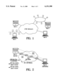
- FIG. 1 also illustrates the situation where Host C represents the source host and Host D represents the destination host, each being directly connected to a LAN which is in turn connected via a router, bridge, Ethernet switch, cell switched router, or other legacy internetworking device to a device with an ATM network interface and preferably supporting QFC.
- switches are termed "ATM-attached edge devices.”
- ATM layer flow control is only in effect between the ATM switches at the boundaries of the ATM network, while TCP flow control is in effect end-to-end. While TCP prevents the destination host from being overrun by the source host, uncoordinated flow control at the ATM layer is unable to prevent the ATM network from being overrun by the source host.
- packets may be lost at the ATM switch closest to Host C, requiring Host C to timeout and retransmit the packets.
- the present invention addresses this situation in a first embodiment by providing ATM layer flow control to Host C in a way that is transparent to Host C and the network to which it is attached. This is done by coupling ATM layer feedback information to TCP's window advertisements, which are carried in the TCP header, using an approach referred to as "Instream Window Management" (IWM). Through the coupling with TCP, the link layer flow control feedback is conveyed transparent to the network hosts; no changes are required in the legacy networks or hosts.
- IWM Instream Window Management
- ATM-layer edge devices are thus provided with explicit control over transport-layer windows.
- Host D sends back window advertisements piggybacked on the TCP headers to the source, Host C.
- the ATM switch closest to the LAN of Host D also referred to as the Egress Intelligent Edge Device or "Egress IED," uses a right edge of the window advertised by Host D as an indication of how many bytes Host D can accept at a given time.
- the Egress IED uses that information to ensure that it does not forward more than that number of bytes to Host D.
- the window right edge limit is reflected in the QFC "forward counter" value that the Egress IED provides to its upstream neighbors.
- the Egress IED as well as all other ATM network elements along the connection avoid cell loss in the direction of Host D.
- an Ingress Intelligent Edge Device can ensure that the LAN cannot overflow that IED's LAN-side input buffers. This is accomplished by the Ingress IED examining the acknowledgment number and the window in the TCP header from the destination host, Host D, and by further constraining the TCP advertised window information seen by the source host, Host C, if required.
- the modified value of the window, passed further upstream to the data source, is referred to as the "Ingress Window.”
- the Ingress IED may also need to generate TCP headers on its own, even in the absence of a TCP header arriving from the destination host. This is necessary when the Ingress IED begins to have more space available on its LAN-side input buffer pool, and thus needs to inform the source host of this status. These locally-generated TCP headers appear to the source host as TCP headers with zero-length segments.
- TCP headers from the destination host passing through the Ingress IED are referred to as Modified Acknowledgments or "Modified ACKs" while those locally generated by the Ingress IED are referred to as Generated Acknowledgments or “Generated ACKs.”
- the Modified ACKs and the Generated ACKs are utilized by the Ingress IED to ensure that the Ingress Window values provided to the source host are consistent with the last Ingress Window value supplied and the actual value of the window as provided by the destination host.
- the flow control enabled by the ATM network is extended both through the Egress IED to the destination host and through the Ingress IED to the source host.
- FIG. 1 illustrates various hosts configured with respect to an ATM network incorporating a reliable flow control protocol
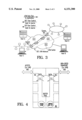
- FIG. 2 illustrates data and flow control paths between two hosts directly connected to a QFC ATM network
- FIG. 3 illustrates data and flow control paths between two hosts indirectly connected to a QFC ATM network
- FIG. 4 represents an Intelligent Edge Device or "IED” according to the present invention
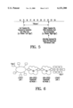
- FIG. 5 is an illustration of information provided in a TCP window advertisement
- FIG. 6 illustrates a further embodiment of the present invention.
- the present invention provides "Instream Window Management" (IWM) to provide coordination between the lower (e.g. Asynchronous Transfer Mode or ATM) and higher (e.g. Transmission Control Protocol/Internet Protocol or TCP/IP) layer protocols.
- IWM Instream Window Management
- U.S. Provisional Patent Applications Ser. Nos. 60/017,504 and 60/019,701 are incorporated herein by reference for the purpose of further illustrating the subject matter of the present invention.
- IWM provides a number of benefits with respect to coordinated flow control. For instance, the present invention avoids deadlocks between the higher and lower layers. IWM dynamically modifies the transport-layer (i.e. TCP/IP layer) window based upon flow control feedback and input buffer availability at the lower layer. IWM is transparent from the point of view of the higher layer flow control. IWM does not require one-to-one mapping of transport-layer flows to lower-layer connections, thus avoiding problems when multiplexing multiple flows on a single stream.
- transport-layer i.e. TCP/IP layer
- the input buffer in an ATM-attached edge device is shared in the present invention among all independent transport-layer flows arriving from the various sources on the attached LAN, and IWM uses the combination of buffer availability and lower layer flow control feedback to manage the transport-layer windows and prevent input buffer overflow. To the extent higher and lower layer multicast mechanisms and connections are in use, IWM includes them in the coordination process to avoid contention between unicast and multicast traffic for available resources. Finally, IWM works seamlessly with existing legacy devices; no change in LAN hosts are required, and no requirements or operational details of the existing lower-layer and transport-layer flow control are violated.
- Higher-layer flow control protocols are typically window-based, employing a receiver-advertised window to limit the number of bytes transmitted from a source (or source host) to the receiver (or destination host).
- the source host must stop transmitting once it has exhausted the window of data which was conveyed to it by the destination host until a subsequent window provides an indication from the destination that more data can be transmitted.
- the size of the window is typically determined, at least in part, by the Round Trip Bandwidth Product (RTBP), which represents the round trip time between the hosts in question multiplied by the bandwidth of the connection. If this number is high, more data can be sent between windows, though any loss will likely require retransmission of a significant quantity of data.
- RTBP Round Trip Bandwidth Product
- the lower-layer is an ATM network providing Quantum Flow Control ("QFC") as described in U.S. patent application Ser. No. 08/847,658, now U.S. Pat. No. 5,781,533, which is assigned to the Assignee of the instant patent application and incorporated herein by reference.
- QFC Quantum Flow Control
- the following discussion refers to the preferred embodiment which utilizes an ATM network or networks as the lower-layer, though the present invention is applicable to any network supporting a lower layer flow control protocol which provides intra-network flow control. The best overall service is provided by the present invention if the lower layer protocol guarantees a reliable, i.e. low loss, service.
- IOM Ingress Input/Output Module
- TCP window-based flow control employs flow control segments, each containing an acknowledgment number and a window, collectively referred to as an acknowledgment or "ACK.”
- ACK acknowledgment
- Each octet transmitted via TCP in the forward direction is assigned a sequence number.
- the TCP destination host checks for corruption or non-delivery of data that may have occurred in the transmission process. If the data are acceptable, the destination host generates an ACK for delivery to the source host in which the acknowledgment number acknowledges all octets up to and including the acknowledgment number less one.
- the window in the ACK indicates the number of additional bytes that the transmitter may send without resulting in buffer overrun at the destination host.
- QFC Quality Flow Control
- Hosts A and B are direct-attached hosts to ATM switches, thereby supporting a Reliable Low Loss (RLL) service end-to-end.
- RLL Reliable Low Loss
- each of the LANs must interface the ATM network through an IED. This is the case for Hosts C and D in FIG. 3.
- IED interfaces enable the extension of the benefits of the reliable lower layer flow control protocol to hosts which are not directly attached to the ATM network.
- FIG. 3 illustrates the ATM switches along the data path between Hosts C and D, and indicates the QFC flow control at the ATM layer, and the end-to-end TCP flow control at the transport layer, the flow control data flowing in the direction opposite of data flow. Though not illustrated, for purposes of simplicity, there is flow control in both directions in the case of data flowing in both directions.
- QFC flow control is only in effect between the ATM edge devices. Therefore, while TCP prevents the destination host from being overrun by the source host, TCP alone is unable to prevent the intermediate ATM network from being overrun by the source host. As a result, packets may be lost at the ATM switch closest to Host C, necessitating the retransmission, and possibly multiple retransmissions, by Host C of the lost packets. To address the situation, the present invention enables the extension of QFC flow control data back to the source host via the Ingress and Egress IEDs.
- the present description assumes one TCP connection mapped to the underlying ATM connection. However, the present invention can also apply to the case of multiple TCP connections per ATM connection. Further, each of the Ingress IED and Egress IED are capable of functioning as the opposite edge device when data flows in the reverse direction.
- TCP enables Host D to send window advertisements back to Host C.
- the Egress IED is given an indication of how many bytes Host D can accept at the present moment from the ATM connection carrying the TCP connection, based upon the right edge of the window in the window advertisement (FIG. 5).
- the Egress IED uses that information to ensure that it does not forward more than the advertised number of bytes to Host D.
- the window right edge limit is reflected in the QFC protocol buffer state that the Egress IED provides to its upstream ATM switch neighbors.
- the Egress IED, as well as all of other QFC elements (e.g. ATM switches) along the presently considered connection avoid cell loss at destination Host D.
- the Ingress IED cannot allow Host C to overflow the LAN-side input buffers of the Ingress IED. This is accomplished by constraining the TCP window advertisement information which was originated by destination Host D.
- the Ingress IED using window modification circuitry (Window Mod. Ckt.) associated with the buffer pool, effectively creates a logical "local window" which tracks available frame buffer space on the LAN-side input buffer pool of the Ingress IED.
- the Ingress IED Based upon this capacity and the TCP window available to Host C, communicated by Host D, the Ingress IED selectively modifies the TCP window advertisements prior to forwarding them to the source host. For example, if the TCP indicated another 1000 bytes of data could be sent on a connection, but the local window of the Ingress IED can support 500 bytes for that connection, Host C will see an advertised TCP window of 500 bytes. As the local buffer space in the Ingress IED becomes available, TCP window advertisements modified by the Ingress IED will be increased until they eventually match the advertisements originated by the destination host.
- FIG. 4 Also illustrated in FIG. 4 are buffers within the buffer pool for handling flow control (F.C.) flowing in the direction reverse to that of the data flow, and Network Line Cards (NLCs) which provide a physical interface to the high-speed transport network, which in the preferred embodiment is an ATM network.
- F.C. flow control
- NLCs Network Line Cards
- the IWM approach is optimized when the LAN of the source host is directly attached to the Ingress IED and similarly when the destination host LAN is directly attached to the Egress IED. However, this approach also functions if either host is attached to an extended LAN, though the possibility of packet loss may then exist in the intermediate bridges and routers connecting the LAN segments.
- the Ingress IED passes through the Ingress IED, the Ingress IED records the values of both the acknowledgment number (last -- seen -- seq, which is the window left edge) and the value of the window in the ACK (the difference between the window edges), and may then modify this window value downward.
- the window value passed further upstream to the source host is referred to as "Ingress Window.”
- the preferred embodiment of the present invention utilizes a hardware implementation of the functions necessary to observe the TCP windows, to modify them as required, and to generate acknowledgments as necessary. For instance, registers are provided for all recorded data values relating to the TCP window advertisements.
- the logic required for parsing the TCP flow control information and for constructing the appropriate acknowledgments is implemented in one or more Application Specific ICs (ASICs).
- ASICs Application Specific ICs
- a first embodiment of the present invention employs the autonomous generation of transport-layer acknowledgments when the lower-layer is ready to accept more traffic.
- the Ingress IED may need to generate ACKs on its own, even in the absence of an ACK arriving from the destination host.
- the connection can make forward progress without relying upon the destination-generated ACKs which are generated only when destination host actually observes more TCP segments on the connection. These locally-generated ACKs appear to the source host as TCP headers with zero-length segments.
- Such Ingress IED-generated acknowledgments are referred to as "generated ACKs," while those produced by the destination host and modified by the Ingress IED are referred to as "modified ACKs.”
- That IED may modify the Ingress Window value such that the window value provided to the source host is
- a smaller Ingress Window value represents a restraint on the buffer space available to this data flow within the Ingress IED.
- the Ingress IED may again modify the window value returned to the source host.
- the Ingress IED may modify the window value from the destination host to be the Ingress Window value such that
- the Ingress IED maintains the "Last -- Ingress -- Window" as well as the last acknowledgment number and last TCP -- Window for each connection.
- the Ingress IED may determine k by subtracting the value of the last acknowledgment number from the current acknowledgment number.
- the Ingress IED can actually reduce the value of the Ingress Window by k from one ACK to the next, as long as the acknowledgment number itself has increased by k. This keeps the right edge of the ACK window non-decreasing. At the other extreme to this example, the Ingress IED may not restrict the window at all, thus providing the source host with the same window that was generated by the destination host.
- the Ingress IED creates an ACK that uses the value of the last acknowledgment number as the current acknowledgment number. For the window value, the Ingress IED provides a new Ingress Window value such that
- Generated ACKs which have the same acknowledgment number as the previous ACK, may appear to the source host as duplicate ACKs which could trigger a fast retransmission by the source host.
- a retransmission need not consume network resources since the Ingress IED is able to determine that the segment being retransmitted was already delivered to the destination host, was the result of a duplicate ACK, and the retransmission can be intelligently dropped and acknowledged by the Ingress IED.
- the Egress IED whenever a TCP ACK from the destination host to the source host passes through the Egress IED, the Egress IED reads the acknowledgment number and window in the ACK and restricts the buffer usage of the data flow at the Egress IED to be consistent with the right edge of the window from the destination host. This restriction on buffer usage propagates backwards through the ATM network via QFC.
- the Egress IED keeps track of the number of bytes F forwarded to the destination host on a per-connection basis. To guarantee no cell loss, the Egress IED must restrict buffer usage until the next ACK such that F is no more than the current right edge of the destination host window.
- the present invention is applicable to a variety of network arrangements between a pair of hosts, each providing some form of end-to-end flow control at an upper layer and a lower layer, intra-network flow control within at least one network intermediate the hosts.
- two high-speed networks, Networks 1 and 2 are shown intermediate Hosts E and F.
- the Ingress IED of Network 2 provides such information to the Egress IED of Network 1.
- each of the high-speed Networks 1 and 2 perform as the prototypical ATM network described above with respect to observing, utilizing and modifying higher-layer flow control information passed between Hosts E and F.
Abstract
Description
ACK(last.sub.-- seen.sub.-- seq, window),
0 <=Ingress.sub.-- Window <=TCP.sub.-- Window
Last.sub.-- Ingress.sub.-- Window - k <=Ingress.sub.-- Window <=TCP.sub.-- Window
Last.sub.-- Ingress.sub.-- Window <=Ingress.sub.-- Window <=Last.sub.-- TCP.sub.-- Window
Claims (57)
Priority Applications (1)
| Application Number | Priority Date | Filing Date | Title |
|---|---|---|---|
| US08/854,231 US6151300A (en) | 1996-05-10 | 1997-05-09 | Method and apparatus for enabling flow control over multiple networks having disparate flow control capability |
Applications Claiming Priority (3)
| Application Number | Priority Date | Filing Date | Title |
|---|---|---|---|
| US1750496P | 1996-05-10 | 1996-05-10 | |
| US1970196P | 1996-06-20 | 1996-06-20 | |
| US08/854,231 US6151300A (en) | 1996-05-10 | 1997-05-09 | Method and apparatus for enabling flow control over multiple networks having disparate flow control capability |
Publications (1)
| Publication Number | Publication Date |
|---|---|
| US6151300A true US6151300A (en) | 2000-11-21 |
Family
ID=26689963
Family Applications (1)
| Application Number | Title | Priority Date | Filing Date |
|---|---|---|---|
| US08/854,231 Expired - Lifetime US6151300A (en) | 1996-05-10 | 1997-05-09 | Method and apparatus for enabling flow control over multiple networks having disparate flow control capability |
Country Status (7)
| Country | Link |
|---|---|
| US (1) | US6151300A (en) |
| EP (1) | EP1021765A4 (en) |
| JP (1) | JP2001501785A (en) |
| CN (1) | CN1104686C (en) |
| AU (1) | AU717590B2 (en) |
| CA (1) | CA2253853A1 (en) |
| WO (1) | WO1997045978A2 (en) |
Cited By (35)
| Publication number | Priority date | Publication date | Assignee | Title |
|---|---|---|---|---|
| WO2001065394A1 (en) * | 2000-02-29 | 2001-09-07 | Rensselaer Polytechnic Institute | Edge-to-edge traffic control for the internet |
| WO2001077850A1 (en) * | 2000-04-06 | 2001-10-18 | Rensselaer Polytechnic Institute | System and method of source based multicast congestion control |
| US20020027888A1 (en) * | 1999-12-23 | 2002-03-07 | Creigh John L. | System and method for providing compatibility between different transceivers in a multi-pair communication system |
| US6438101B1 (en) * | 1997-12-23 | 2002-08-20 | At&T Corp. | Method and apparatus for managing congestion within an internetwork using window adaptation |
| US6452915B1 (en) | 1998-07-10 | 2002-09-17 | Malibu Networks, Inc. | IP-flow classification in a wireless point to multi-point (PTMP) transmission system |
| WO2002098064A1 (en) * | 2001-05-31 | 2002-12-05 | Turin Networks | Distributed control of data flow in a network switch |
| US6590885B1 (en) | 1998-07-10 | 2003-07-08 | Malibu Networks, Inc. | IP-flow characterization in a wireless point to multi-point (PTMP) transmission system |
| US6594246B1 (en) | 1998-07-10 | 2003-07-15 | Malibu Networks, Inc. | IP-flow identification in a wireless point to multi-point transmission system |
| US6597704B1 (en) * | 1998-10-07 | 2003-07-22 | Nortel Networks Limited | System for translating a message from a first transmission protocol to a second transmission protocol |
| US20030149715A1 (en) * | 2000-07-24 | 2003-08-07 | Jussi Ruutu | Flow control |
| WO2003075486A1 (en) * | 2002-03-06 | 2003-09-12 | Telefonaktiebolaget L M Ericsson | Method and system of load control |
| US6628629B1 (en) | 1998-07-10 | 2003-09-30 | Malibu Networks | Reservation based prioritization method for wireless transmission of latency and jitter sensitive IP-flows in a wireless point to multi-point transmission system |
| US6640248B1 (en) | 1998-07-10 | 2003-10-28 | Malibu Networks, Inc. | Application-aware, quality of service (QoS) sensitive, media access control (MAC) layer |
| US6680922B1 (en) | 1998-07-10 | 2004-01-20 | Malibu Networks, Inc. | Method for the recognition and operation of virtual private networks (VPNs) over a wireless point to multi-point (PtMP) transmission system |
| US20040013551A1 (en) * | 2002-07-22 | 2004-01-22 | Milton Skillman | Bottom discharge valve |
| US20040030797A1 (en) * | 2002-08-12 | 2004-02-12 | Cuneyt Akinlar | Quality of service management in network gateways |
| US6721413B1 (en) * | 1999-01-06 | 2004-04-13 | Nec Corporation | Method and apparatus for observing and controlling a multi-layered communication network |
| WO2004036845A1 (en) * | 2002-10-18 | 2004-04-29 | Telefonaktiebolaget Lm Ericsson (Publ) | Arrangements and method for controlling transmission of data bits |
| US20040085902A1 (en) * | 2002-11-05 | 2004-05-06 | Pierre Miller | Method and system for extending the reach of a data communication channel using a flow control interception device |
| US6747954B1 (en) * | 1997-12-19 | 2004-06-08 | Telefonaktiebolaget Lm Ericsson (Publ) | Asynchronous transfer mode switch providing pollstate status information |
| US6765889B1 (en) * | 1997-07-14 | 2004-07-20 | Telefonaktiebolaget Lm Ericsson (Publ) | Communication method and system |
| US6862622B2 (en) | 1998-07-10 | 2005-03-01 | Van Drebbel Mariner Llc | Transmission control protocol/internet protocol (TCP/IP) packet-centric wireless point to multi-point (PTMP) transmission system architecture |
| US6882624B1 (en) * | 1998-04-09 | 2005-04-19 | Nokia Networks Oy | Congestion and overload control in a packet switched network |
| US20050243722A1 (en) * | 2004-04-30 | 2005-11-03 | Zhen Liu | Method and apparatus for group communication with end-to-end reliability |
| WO2007095967A1 (en) * | 2006-02-27 | 2007-08-30 | Telefonaktiebolaget Lm Ericsson (Publ) | Flow control mechanism using local and global acknowledgements |
| US20090296583A1 (en) * | 2008-05-29 | 2009-12-03 | Dolezilek David J | Systems, Methods, and Apparatus for Recording Network Events Associated with a Power Generation or Delivery System |
| US20090319701A1 (en) * | 2008-06-04 | 2009-12-24 | Microsoft Corporation | Simple Flow Control Protocol Over RDMA |
| US20100039954A1 (en) * | 2008-08-18 | 2010-02-18 | Abb Technology Ag | Analyzing communication configuration in a process control system |
| US20100157803A1 (en) * | 2008-12-18 | 2010-06-24 | James Paul Rivers | Method and system to manage network traffic congestion in networks with link layer flow control |
| US20140160981A1 (en) * | 2001-03-19 | 2014-06-12 | Juniper Networks, Inc. | Transport networks supporting virtual private networks, and configuring such networks |
| US20140269302A1 (en) * | 2013-03-14 | 2014-09-18 | Cisco Technology, Inc. | Intra Switch Transport Protocol |
| US9628406B2 (en) | 2013-03-13 | 2017-04-18 | Cisco Technology, Inc. | Intra switch transport protocol |
| US10122645B2 (en) | 2012-12-07 | 2018-11-06 | Cisco Technology, Inc. | Output queue latency behavior for input queue based device |
| US11677663B2 (en) | 2021-08-12 | 2023-06-13 | Schweitzer Engineering Laboratories, Inc. | Software-defined network statistics extension |
| US11882002B2 (en) | 2022-06-22 | 2024-01-23 | Schweitzer Engineering Laboratories, Inc. | Offline test mode SDN validation |
Families Citing this family (10)
| Publication number | Priority date | Publication date | Assignee | Title |
|---|---|---|---|---|
| FI980825A (en) * | 1998-04-09 | 1999-10-10 | Nokia Networks Oy | Control of congestion in telecommunications networks |
| US6370114B1 (en) | 1997-12-31 | 2002-04-09 | Nortel Networks Limited | Apparatus and method for optimizing congestion control information in a multi-protocol network |
| FI980826A (en) * | 1998-04-09 | 1999-10-10 | Nokia Networks Oy | Control of congestion in telecommunications networks |
| US6643292B2 (en) | 1998-04-28 | 2003-11-04 | Nortel Networks Limited | Efficient packet data transport mechanism and an interface therefor |
| US6215769B1 (en) * | 1998-10-07 | 2001-04-10 | Nokia Telecommunications, Inc. | Enhanced acknowledgment pacing device and method for TCP connections |
| IT1303842B1 (en) * | 1998-11-20 | 2001-03-01 | Cit Alcatel | TELECOMMUNICATION NETWORK WITH A TRANSPORT LAYER CONTROLLED BY A LAYER WITH INTERNET PROTOCOL |
| FI109061B (en) | 2000-05-10 | 2002-05-15 | Nokia Corp | Resource reservation on a packet network |
| US7305483B2 (en) * | 2002-04-25 | 2007-12-04 | Yahoo! Inc. | Method for the real-time distribution of streaming data on a network |
| WO2005074210A1 (en) * | 2004-01-30 | 2005-08-11 | Telefonaktiebolaget Lm Ericsson (Publ) | Method for transferring packets in networks comprising a plurality of linked intermediate networks |
| GB2465595B (en) | 2008-11-21 | 2010-12-08 | Nokia Corp | A method and an apparatus for a gateway |
Citations (9)
| Publication number | Priority date | Publication date | Assignee | Title |
|---|---|---|---|---|
| US5313454A (en) * | 1992-04-01 | 1994-05-17 | Stratacom, Inc. | Congestion control for cell networks |
| US5493566A (en) * | 1992-12-15 | 1996-02-20 | Telefonaktiebolaget L M. Ericsson | Flow control system for packet switches |
| US5515359A (en) * | 1994-08-26 | 1996-05-07 | Mitsubishi Electric Research Laboratories, Inc. | Credit enhanced proportional rate control system |
| US5528591A (en) * | 1995-01-31 | 1996-06-18 | Mitsubishi Electric Research Laboratories, Inc. | End-to-end credit-based flow control system in a digital communication network |
| US5583865A (en) * | 1993-04-20 | 1996-12-10 | Kabushiki Kaisha Toshiba | ATM communication system with high speed connection-less service function |
| US5600798A (en) * | 1993-10-26 | 1997-02-04 | International Business Machines Corporation | System and method for controlling LAN data flow control through a frame relay network by end point station transmitting notification to LAN stations based on congestion notification from the frame relay network |
| US5787071A (en) * | 1994-11-08 | 1998-07-28 | International Business Machines | Hop-by-hop flow control in an ATM network |
| US5852601A (en) * | 1991-09-09 | 1998-12-22 | Network Equipment Technologies, Inc. | Method and apparatus for reactive congestion control in an asynchronous transfer mode (ATM) network |
| US5889761A (en) * | 1995-03-24 | 1999-03-30 | Kabushiki Kaisha Toshiba | Method and system for controlling cell transmission rate in ATM network using resource management cell |
Family Cites Families (6)
| Publication number | Priority date | Publication date | Assignee | Title |
|---|---|---|---|---|
| US5021949A (en) * | 1988-02-29 | 1991-06-04 | International Business Machines Corporation | Method and apparatus for linking an SNA host to a remote SNA host over a packet switched communications network |
| GB2227341A (en) * | 1989-01-18 | 1990-07-25 | Intel Corp | Message routing in a multiprocessor computer system |
| US5303344A (en) * | 1989-03-13 | 1994-04-12 | Hitachi, Ltd. | Protocol processing apparatus for use in interfacing network connected computer systems utilizing separate paths for control information and data transfer |
| US5557798A (en) * | 1989-07-27 | 1996-09-17 | Tibco, Inc. | Apparatus and method for providing decoupling of data exchange details for providing high performance communication between software processes |
| US5619650A (en) * | 1992-12-31 | 1997-04-08 | International Business Machines Corporation | Network processor for transforming a message transported from an I/O channel to a network by adding a message identifier and then converting the message |
| JP2576780B2 (en) * | 1993-12-17 | 1997-01-29 | 日本電気株式会社 | Protocol termination method |
-
1997
- 1997-05-09 WO PCT/US1997/008116 patent/WO1997045978A2/en not_active Application Discontinuation
- 1997-05-09 EP EP97924708A patent/EP1021765A4/en not_active Withdrawn
- 1997-05-09 JP JP09542499A patent/JP2001501785A/en active Pending
- 1997-05-09 CN CN97195544.1A patent/CN1104686C/en not_active Expired - Fee Related
- 1997-05-09 US US08/854,231 patent/US6151300A/en not_active Expired - Lifetime
- 1997-05-09 CA CA002253853A patent/CA2253853A1/en not_active Abandoned
- 1997-05-09 AU AU30060/97A patent/AU717590B2/en not_active Ceased
Patent Citations (9)
| Publication number | Priority date | Publication date | Assignee | Title |
|---|---|---|---|---|
| US5852601A (en) * | 1991-09-09 | 1998-12-22 | Network Equipment Technologies, Inc. | Method and apparatus for reactive congestion control in an asynchronous transfer mode (ATM) network |
| US5313454A (en) * | 1992-04-01 | 1994-05-17 | Stratacom, Inc. | Congestion control for cell networks |
| US5493566A (en) * | 1992-12-15 | 1996-02-20 | Telefonaktiebolaget L M. Ericsson | Flow control system for packet switches |
| US5583865A (en) * | 1993-04-20 | 1996-12-10 | Kabushiki Kaisha Toshiba | ATM communication system with high speed connection-less service function |
| US5600798A (en) * | 1993-10-26 | 1997-02-04 | International Business Machines Corporation | System and method for controlling LAN data flow control through a frame relay network by end point station transmitting notification to LAN stations based on congestion notification from the frame relay network |
| US5515359A (en) * | 1994-08-26 | 1996-05-07 | Mitsubishi Electric Research Laboratories, Inc. | Credit enhanced proportional rate control system |
| US5787071A (en) * | 1994-11-08 | 1998-07-28 | International Business Machines | Hop-by-hop flow control in an ATM network |
| US5528591A (en) * | 1995-01-31 | 1996-06-18 | Mitsubishi Electric Research Laboratories, Inc. | End-to-end credit-based flow control system in a digital communication network |
| US5889761A (en) * | 1995-03-24 | 1999-03-30 | Kabushiki Kaisha Toshiba | Method and system for controlling cell transmission rate in ATM network using resource management cell |
Cited By (58)
| Publication number | Priority date | Publication date | Assignee | Title |
|---|---|---|---|---|
| US6765889B1 (en) * | 1997-07-14 | 2004-07-20 | Telefonaktiebolaget Lm Ericsson (Publ) | Communication method and system |
| US6747954B1 (en) * | 1997-12-19 | 2004-06-08 | Telefonaktiebolaget Lm Ericsson (Publ) | Asynchronous transfer mode switch providing pollstate status information |
| US6438101B1 (en) * | 1997-12-23 | 2002-08-20 | At&T Corp. | Method and apparatus for managing congestion within an internetwork using window adaptation |
| US6882624B1 (en) * | 1998-04-09 | 2005-04-19 | Nokia Networks Oy | Congestion and overload control in a packet switched network |
| US6594246B1 (en) | 1998-07-10 | 2003-07-15 | Malibu Networks, Inc. | IP-flow identification in a wireless point to multi-point transmission system |
| US9712289B2 (en) | 1998-07-10 | 2017-07-18 | Intellectual Ventures I Llc | Transmission control protocol/internet protocol (TCP/IP) packet-centric wireless point to multi-point (PtMP) transmission system architecture |
| US6590885B1 (en) | 1998-07-10 | 2003-07-08 | Malibu Networks, Inc. | IP-flow characterization in a wireless point to multi-point (PTMP) transmission system |
| US6862622B2 (en) | 1998-07-10 | 2005-03-01 | Van Drebbel Mariner Llc | Transmission control protocol/internet protocol (TCP/IP) packet-centric wireless point to multi-point (PTMP) transmission system architecture |
| US6452915B1 (en) | 1998-07-10 | 2002-09-17 | Malibu Networks, Inc. | IP-flow classification in a wireless point to multi-point (PTMP) transmission system |
| USRE46206E1 (en) | 1998-07-10 | 2016-11-15 | Intellectual Ventures I Llc | Method and computer program product for internet protocol (IP)—flow classification in a wireless point to multi-point (PTMP) transmission system |
| US6628629B1 (en) | 1998-07-10 | 2003-09-30 | Malibu Networks | Reservation based prioritization method for wireless transmission of latency and jitter sensitive IP-flows in a wireless point to multi-point transmission system |
| US6640248B1 (en) | 1998-07-10 | 2003-10-28 | Malibu Networks, Inc. | Application-aware, quality of service (QoS) sensitive, media access control (MAC) layer |
| US6680922B1 (en) | 1998-07-10 | 2004-01-20 | Malibu Networks, Inc. | Method for the recognition and operation of virtual private networks (VPNs) over a wireless point to multi-point (PtMP) transmission system |
| US6597704B1 (en) * | 1998-10-07 | 2003-07-22 | Nortel Networks Limited | System for translating a message from a first transmission protocol to a second transmission protocol |
| US6721413B1 (en) * | 1999-01-06 | 2004-04-13 | Nec Corporation | Method and apparatus for observing and controlling a multi-layered communication network |
| US20020027888A1 (en) * | 1999-12-23 | 2002-03-07 | Creigh John L. | System and method for providing compatibility between different transceivers in a multi-pair communication system |
| US6965610B2 (en) * | 1999-12-23 | 2005-11-15 | Broadcom Corporation | System and method for providing compatibility between different transceivers in a multi-pair communication system |
| WO2001065394A1 (en) * | 2000-02-29 | 2001-09-07 | Rensselaer Polytechnic Institute | Edge-to-edge traffic control for the internet |
| WO2001077850A1 (en) * | 2000-04-06 | 2001-10-18 | Rensselaer Polytechnic Institute | System and method of source based multicast congestion control |
| US20040049593A1 (en) * | 2000-04-06 | 2004-03-11 | Shivkumar Kalyanaraman | System and method of source based multicast congrestion control |
| US7020714B2 (en) | 2000-04-06 | 2006-03-28 | Rensselaer Polytechnic Institute | System and method of source based multicast congestion control |
| US20030149715A1 (en) * | 2000-07-24 | 2003-08-07 | Jussi Ruutu | Flow control |
| US9042271B2 (en) * | 2001-03-19 | 2015-05-26 | Juniper Networks, Inc. | Transport networks supporting virtual private networks, and configuring such networks |
| US20140160981A1 (en) * | 2001-03-19 | 2014-06-12 | Juniper Networks, Inc. | Transport networks supporting virtual private networks, and configuring such networks |
| WO2002098064A1 (en) * | 2001-05-31 | 2002-12-05 | Turin Networks | Distributed control of data flow in a network switch |
| US7006438B2 (en) * | 2001-05-31 | 2006-02-28 | Turin Networks | Distributed control of data flow in a network switch |
| WO2003075486A1 (en) * | 2002-03-06 | 2003-09-12 | Telefonaktiebolaget L M Ericsson | Method and system of load control |
| US7672279B2 (en) | 2002-03-06 | 2010-03-02 | Telefonaktiebolaget L M Ericsson (Publ) | Methods for dynamic radio resource management and link control |
| US20050170841A1 (en) * | 2002-03-06 | 2005-08-04 | Mats Sagfors | Method and system of load control |
| US20040013551A1 (en) * | 2002-07-22 | 2004-01-22 | Milton Skillman | Bottom discharge valve |
| US7802008B2 (en) * | 2002-08-12 | 2010-09-21 | Matsushita Electric Industrial Co., Ltd. | Quality of service management in network gateways |
| US20040030797A1 (en) * | 2002-08-12 | 2004-02-12 | Cuneyt Akinlar | Quality of service management in network gateways |
| WO2004036845A1 (en) * | 2002-10-18 | 2004-04-29 | Telefonaktiebolaget Lm Ericsson (Publ) | Arrangements and method for controlling transmission of data bits |
| US20060007934A1 (en) * | 2002-10-18 | 2006-01-12 | Svetlana Chemiakina | Arrangements and method for controlling transmission of data bits |
| US6859437B2 (en) * | 2002-11-05 | 2005-02-22 | Nortel Networks Limited | Method and system for extending the reach of a data communication channel using a flow control interception device |
| US20050157648A1 (en) * | 2002-11-05 | 2005-07-21 | Nortel Networks Limited | Method and system for extending the reach of a data communication channel using a flow control interception device |
| US7209445B2 (en) * | 2002-11-05 | 2007-04-24 | Nortel Networks Limited | Method and system for extending the reach of a data communication channel using a flow control interception device |
| US20040085902A1 (en) * | 2002-11-05 | 2004-05-06 | Pierre Miller | Method and system for extending the reach of a data communication channel using a flow control interception device |
| WO2004043129A2 (en) * | 2002-11-05 | 2004-05-27 | Nortel Networks Limited | Method and system for extending the reach of a data communication channel using a flow control interception device |
| WO2004043129A3 (en) * | 2002-11-05 | 2004-07-08 | Nortel Networks Ltd | Method and system for extending the reach of a data communication channel using a flow control interception device |
| US7355975B2 (en) | 2004-04-30 | 2008-04-08 | International Business Machines Corporation | Method and apparatus for group communication with end-to-end reliability |
| WO2005109772A3 (en) * | 2004-04-30 | 2006-10-19 | Ibm | Method and apparatus for group communication with end-to-end reliability |
| US20050243722A1 (en) * | 2004-04-30 | 2005-11-03 | Zhen Liu | Method and apparatus for group communication with end-to-end reliability |
| US8238242B2 (en) | 2006-02-27 | 2012-08-07 | Telefonaktiebolaget Lm Ericsson (Publ) | Flow control mechanism using local and global acknowledgements |
| WO2007095967A1 (en) * | 2006-02-27 | 2007-08-30 | Telefonaktiebolaget Lm Ericsson (Publ) | Flow control mechanism using local and global acknowledgements |
| US20090296583A1 (en) * | 2008-05-29 | 2009-12-03 | Dolezilek David J | Systems, Methods, and Apparatus for Recording Network Events Associated with a Power Generation or Delivery System |
| US8024417B2 (en) | 2008-06-04 | 2011-09-20 | Microsoft Corporation | Simple flow control protocol over RDMA |
| US20090319701A1 (en) * | 2008-06-04 | 2009-12-24 | Microsoft Corporation | Simple Flow Control Protocol Over RDMA |
| US8804547B2 (en) * | 2008-08-18 | 2014-08-12 | Abb Technology Ag | Analyzing communication configuration in a process control system |
| US20100039954A1 (en) * | 2008-08-18 | 2010-02-18 | Abb Technology Ag | Analyzing communication configuration in a process control system |
| US8325602B2 (en) * | 2008-12-18 | 2012-12-04 | Cisco Technology, Inc. | Method and system to manage network traffic congestion in networks with link layer flow control |
| US20100157803A1 (en) * | 2008-12-18 | 2010-06-24 | James Paul Rivers | Method and system to manage network traffic congestion in networks with link layer flow control |
| US10122645B2 (en) | 2012-12-07 | 2018-11-06 | Cisco Technology, Inc. | Output queue latency behavior for input queue based device |
| US9628406B2 (en) | 2013-03-13 | 2017-04-18 | Cisco Technology, Inc. | Intra switch transport protocol |
| US20140269302A1 (en) * | 2013-03-14 | 2014-09-18 | Cisco Technology, Inc. | Intra Switch Transport Protocol |
| US9860185B2 (en) * | 2013-03-14 | 2018-01-02 | Cisco Technology, Inc. | Intra switch transport protocol |
| US11677663B2 (en) | 2021-08-12 | 2023-06-13 | Schweitzer Engineering Laboratories, Inc. | Software-defined network statistics extension |
| US11882002B2 (en) | 2022-06-22 | 2024-01-23 | Schweitzer Engineering Laboratories, Inc. | Offline test mode SDN validation |
Also Published As
| Publication number | Publication date |
|---|---|
| CA2253853A1 (en) | 1997-12-04 |
| EP1021765A4 (en) | 2005-06-08 |
| JP2001501785A (en) | 2001-02-06 |
| WO1997045978A3 (en) | 1998-01-08 |
| CN1104686C (en) | 2003-04-02 |
| WO1997045978A2 (en) | 1997-12-04 |
| CN1224518A (en) | 1999-07-28 |
| AU717590B2 (en) | 2000-03-30 |
| AU3006097A (en) | 1998-01-05 |
| EP1021765A2 (en) | 2000-07-26 |
Similar Documents
| Publication | Publication Date | Title |
|---|---|---|
| US6151300A (en) | Method and apparatus for enabling flow control over multiple networks having disparate flow control capability | |
| US9008100B2 (en) | Wavefront detection and disambiguation of acknowledgments | |
| US8824490B2 (en) | Automatic detection and window virtualization for flow control | |
| US7630305B2 (en) | TCP selective acknowledgements for communicating delivered and missed data packets | |
| US7656799B2 (en) | Flow control system architecture | |
| US8233392B2 (en) | Transaction boundary detection for reduction in timeout penalties | |
| US7698453B2 (en) | Early generation of acknowledgements for flow control | |
| US6219713B1 (en) | Method and apparatus for adjustment of TCP sliding window with information about network conditions | |
| Goyal et al. | Improving the Performance of TCP over the ATM-UBR Service | |
| EP0454364B1 (en) | High speed transport protocol with two windows | |
| US6621829B1 (en) | Method and apparatus for the prioritization of control plane traffic in a router | |
| Lee et al. | A simulation study of TCP performance over IEEE 1394 home networks | |
| EP1652087B1 (en) | Flow control architecture | |
| Bauer et al. | An error-control scheme for a multicast protocol based on round-trip time calculations | |
| Sisalem et al. | Binary congestion notification in TCP | |
| Chang et al. | Improved WWW multimedia transmission performance in HTTP/TCP over ATM networks | |
| Nair et al. | 312 Global Information Infrastructure (GII) Evolution S. Rao et al.(Eds.) IOS Press, 1996 | |
| Reddy et al. | A model for an efficient explicit congestion reduction in high traffic high speed networks through automated rate controlling | |
| Koike | TCP conformance for network-based control | |
| Reddy et al. | A REFINED NEW MODEL FOR EFFICIENT EXPLICIT CONGESTION REDUCTION IN HIGH TRAFFIC HIGH SPEED NETWORKS THROUGH AUTOMATED RATE CONTROLLING | |
| Lazaris et al. | High speed transport protocols: an attempt to find the best solution | |
| Diaz-Nieves | Enhanced transport protocol: a transport protocol for high-speed networking | |
| Spengler | AD-A261 068 i |
Legal Events
| Date | Code | Title | Description |
|---|---|---|---|
| AS | Assignment |
Owner name: ASCOM NEXION INC., MASSACHUSETTS Free format text: ASSIGNMENT OF ASSIGNORS INTEREST;ASSIGNORS:HUNT, DOUGLAS H.;NAIR, RAJ KRISHNAN;MALIS, ANDREW G.;REEL/FRAME:008749/0333;SIGNING DATES FROM 19970618 TO 19970623 |
|
| AS | Assignment |
Owner name: ASCOM TIMPLEX TRADING A.G., SWITZERLAND Free format text: ASSENT TO PATENT ASSIGNMENTS;ASSIGNOR:ASCOM TIMPLEX, INC.;REEL/FRAME:009604/0797 Effective date: 19970609 Owner name: FUJITSU NETWORK COMMUNICATIONS, INC., TEXAS Free format text: ASSIGNMENT OF ASSIGNORS INTEREST;ASSIGNOR:ASCOM TIMPLEX TRADING A.G.;REEL/FRAME:009604/0822 Effective date: 19970609 Owner name: ASCOM TIMPLEX TRADING A.G.A CORPORATION OF SWITZER Free format text: ASSIGNMENT OF ASSIGNORS INTEREST;ASSIGNOR:ASCOM NEXION, INC.;REEL/FRAME:009610/0358 Effective date: 19970609 |
|
| AS | Assignment |
Owner name: FUJITSU LIMITED, JAPAN Free format text: CONFIRMATORY ASSIGNMENT OF JOINT OWERSHIP;ASSIGNOR:FUJITSU NETWORK COMMUNICATIONS, INC.;REEL/FRAME:009621/0656 Effective date: 19981124 |
|
| STCF | Information on status: patent grant |
Free format text: PATENTED CASE |
|
| FEPP | Fee payment procedure |
Free format text: PAYOR NUMBER ASSIGNED (ORIGINAL EVENT CODE: ASPN); ENTITY STATUS OF PATENT OWNER: LARGE ENTITY |
|
| FPAY | Fee payment |
Year of fee payment: 4 |
|
| FEPP | Fee payment procedure |
Free format text: PAYER NUMBER DE-ASSIGNED (ORIGINAL EVENT CODE: RMPN); ENTITY STATUS OF PATENT OWNER: LARGE ENTITY Free format text: PAYOR NUMBER ASSIGNED (ORIGINAL EVENT CODE: ASPN); ENTITY STATUS OF PATENT OWNER: LARGE ENTITY |
|
| FEPP | Fee payment procedure |
Free format text: PAYOR NUMBER ASSIGNED (ORIGINAL EVENT CODE: ASPN); ENTITY STATUS OF PATENT OWNER: LARGE ENTITY Free format text: PAYER NUMBER DE-ASSIGNED (ORIGINAL EVENT CODE: RMPN); ENTITY STATUS OF PATENT OWNER: LARGE ENTITY |
|
| FPAY | Fee payment |
Year of fee payment: 8 |
|
| FPAY | Fee payment |
Year of fee payment: 12 |