US6149807A - Self-locking filter-screen feeding device - Google Patents
Self-locking filter-screen feeding device Download PDFInfo
- Publication number
- US6149807A US6149807A US09/359,889 US35988999A US6149807A US 6149807 A US6149807 A US 6149807A US 35988999 A US35988999 A US 35988999A US 6149807 A US6149807 A US 6149807A
- Authority
- US
- United States
- Prior art keywords
- carriage
- filter
- filter band
- feeding device
- screen
- Prior art date
- Legal status (The legal status is an assumption and is not a legal conclusion. Google has not performed a legal analysis and makes no representation as to the accuracy of the status listed.)
- Expired - Fee Related
Links
- 229920003023 plastic Polymers 0.000 claims abstract description 16
- 239000004033 plastic Substances 0.000 claims abstract description 16
- 239000000463 material Substances 0.000 claims abstract description 15
- 230000000284 resting effect Effects 0.000 claims abstract description 14
- 230000009969 flowable effect Effects 0.000 claims description 4
- 238000001914 filtration Methods 0.000 description 2
- 239000013536 elastomeric material Substances 0.000 description 1
- 239000011236 particulate material Substances 0.000 description 1
- 238000011084 recovery Methods 0.000 description 1
- 238000007789 sealing Methods 0.000 description 1
- 229920002994 synthetic fiber Polymers 0.000 description 1
- 238000011144 upstream manufacturing Methods 0.000 description 1
- 238000004804 winding Methods 0.000 description 1
Images

Classifications
-
- B—PERFORMING OPERATIONS; TRANSPORTING
- B01—PHYSICAL OR CHEMICAL PROCESSES OR APPARATUS IN GENERAL
- B01D—SEPARATION
- B01D29/00—Filters with filtering elements stationary during filtration, e.g. pressure or suction filters, not covered by groups B01D24/00 - B01D27/00; Filtering elements therefor
- B01D29/09—Filters with filtering elements stationary during filtration, e.g. pressure or suction filters, not covered by groups B01D24/00 - B01D27/00; Filtering elements therefor with filtering bands, e.g. movable between filtering operations
- B01D29/096—Construction of filtering bands or supporting belts, e.g. devices for centering, mounting or sealing the filtering bands or the supporting belts
-
- B—PERFORMING OPERATIONS; TRANSPORTING
- B29—WORKING OF PLASTICS; WORKING OF SUBSTANCES IN A PLASTIC STATE IN GENERAL
- B29C—SHAPING OR JOINING OF PLASTICS; SHAPING OF MATERIAL IN A PLASTIC STATE, NOT OTHERWISE PROVIDED FOR; AFTER-TREATMENT OF THE SHAPED PRODUCTS, e.g. REPAIRING
- B29C48/00—Extrusion moulding, i.e. expressing the moulding material through a die or nozzle which imparts the desired form; Apparatus therefor
- B29C48/25—Component parts, details or accessories; Auxiliary operations
- B29C48/36—Means for plasticising or homogenising the moulding material or forcing it through the nozzle or die
- B29C48/50—Details of extruders
- B29C48/69—Filters or screens for the moulding material
- B29C48/692—Filters or screens for the moulding material in the form of webs displaceable for using adjacent areas consecutively
-
- B—PERFORMING OPERATIONS; TRANSPORTING
- B29—WORKING OF PLASTICS; WORKING OF SUBSTANCES IN A PLASTIC STATE IN GENERAL
- B29C—SHAPING OR JOINING OF PLASTICS; SHAPING OF MATERIAL IN A PLASTIC STATE, NOT OTHERWISE PROVIDED FOR; AFTER-TREATMENT OF THE SHAPED PRODUCTS, e.g. REPAIRING
- B29C48/00—Extrusion moulding, i.e. expressing the moulding material through a die or nozzle which imparts the desired form; Apparatus therefor
- B29C48/03—Extrusion moulding, i.e. expressing the moulding material through a die or nozzle which imparts the desired form; Apparatus therefor characterised by the shape of the extruded material at extrusion
Definitions
- the present invention relates to a screen feeding device for a filter apparatus of the type comprising a flow-path for a flowable plastic material to be filtered, in which a continuous filter screen is transversally movable to the flow-path of the plastic material and drawn for periodically advancing the filter screen to substitute a clogged area of the filter with a clean one in said flow-path.
- Filter devices therefore have been suggested which make use of a filter screen in the form of a strip or band, usually formed by a continuous screen member having very small mesh, which is periodically advanced each time a filter area of the screen become soiled and tend to clog, to be replaced with a clean one, reducing to a minimum and possibly eliminating intervention by any operator and the down time of the plant.
- U.S. Pat. No. 3,971,721 describes a continuous filter device in which a screen or a continuous filter strip is advanced through a guide channel of a predeterminate cross-sectional size, and carries a plurality of seal members spaced apart along its length to form moving seals.
- the filter strip is continuously or periodically moved, across the flow-path of the molten plastic material, by an endless draw device having protruding arms to engage the sealing members at the outlet side of the filter strip from the filter device.
- U.S. Pat. No. 4,842,750 suggests the use of a special filter device comprising axially movable tubular portions defining a path for the molten plastic material, to enlarge the volume upstream a strip-shaped screen, to reduce pressure, avoiding synthetic material from escaping when the filter screen is advanced to substitute a clogged area with a clean one.
- the screen strip is advanced by a drive connected to a drum from which the screen is unwound or respectively is wound up.
- An object of the present invention is therefore to provide a feeding device for a continuous filter screen in a filter apparatus for plastic material, which is of simple design and allows for an accurate advancement of the filter screen, at each change.
- Another object of the invention is to provide a self-locking feeding device for a filter screen as stated above, in which any reaction to the advancement by the screen or filter member, will tend to increase the drawing force exerted on the same screen by the feeding device.
- Another object of the present invention is to provide a feeding device for the net screen of a filter apparatus, in which the step feeding is simply controlled mechanically during each change.
- a screen feeding device for a filter apparatus of the type comprising a flow-path for a flowable plastic material to be filtered by a screen in the form of a filter band transversely movable to the flow-path, and draw means for periodically advancing the filter band to substitute a clogged area with a clean one in said flow-path, the feeding device comprising:
- At least one rotatable pressure member fastened to a shaft on the carriage, for engaging and pressing the filter band against said surface means
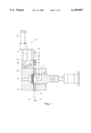
- FIG. 1 schematically shows a filter apparatus provided with a screen feeding device according to the invention
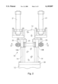
- FIG. 2 is a side view of the screen feeding device of FIG. 1;
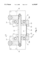
- FIG. 3 is a cross-sectional view according to line 3--3 of FIG. 2;
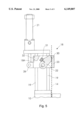
- FIG. 4 is a view according to line 4--4 of FIG. 3 of the screen feeding device, in the retracted inoperative condition;
- FIG. 5 is a view according to line 4--4 of FIG. 3 of the feeding device, in the advanced operative condition.
- reference 10 indicates the body of a filter apparatus for flowable plastic material of any suitable type, comprising a flow-path extending between an inlet 11 and an outlet 12 as shown; in the same figure, reference number 13 indicates a screen feeding device for drawing a filter screen 14 in the form of a continuous filter band, to step advance the same in the sense of arrow 15 inside a filter chamber and across the flow-path 11, 12 for the molten plastic material, between an inlet 16 and an outlet side 17 for the same filter band 14.
- the feeding device 13 comprising a carriage 18 which may be reciprocated along guide members, for example in the form of rails or guide rods 19, which extend from a base plate 20 fastened to the body 10 of the filter device, on one side and parallely to the filter band 14.
- Drive means 21 in the form of linear actuators, for example two pressure actuated cylinders or any other suitable actuator devices, are provided to selectively reciprocate the carriage 18 along the guide rods 19, and angularly rotate one or more pressure members 22, to urge and lock the filter band 14 against surface means 23 for supporting and drawing forwards the filter band 14 during each reciprocation of the carriage 18, from the retracted position of FIGS. 1, 2 and 4, to the advanced position of FIG. 5.
- the pressure member or each pressure member 22 is supported by a shaft 24 to be angularly rotated to and from the resting surface 23, operatively in a direction opposite to the advancement direction 15 for the filter band 14; as will be explained further with reference to the FIGS. 4 and 5, the reverse rotation and slanted disposition of the pressure member 22 will result in a self-locking action of the same pressure member 22 which will be backwards rotated at any reaction of the filter band 14, to press and lock the filter band 14 against the resting surface 23, preventing any slippage.
- the carriage 18 and the resting surface 23 for the filter band 14, and the pressure member or members 22, may be of any other constructional type, in respect to what shown, comprising a slider movable on side rails; for example the carriage 18 may be of a single piece or of two or more pieces joined each other.
- the carriage 18 comprises two carriage members 18A and 18B, slidably supported by respective guide rods 19.
- Each carriage member 18A and 18B is provided with a pressure member 22 running along a longitudinal edge of the filter band 14, in correspondence of a respective resting surface 23 provided by a shoulder or wall member inwardly protruding; a plate 26 is bridging the shoulders 23 to better support the filter band 14, and to connect both carriage members 18A and 18B.
- the two carriage members 18A and 18B are conjointly reciprocated by respective actuators 21 having the piston rod 25 linked by a crank arm 26 to the shaft 24 rotatably supported and transversely extending between the two carriage members 18A and 18B.
- each actuator 21 is supported at the end of the guide rods 19 which is opposite to the filter device 10; nevertheless any other type and disposition of the actuator 21 in respect to the filter device 10 and the carriage 18 may be used or devised for the purpose of the present invention.
- each pressure member 22 is in the form of an elongated self-locking detent member, angularly oriented in the forward moving direction of the carriage 18; each pressure member 22, near the front end and on the side facing the resting surface 23 is provided with a pressure edge 30 having a rounded shape to provide a contact surface with the filter band 14 having a short width to increase the pressure force against the filter band and the resting surface 23 to prevent slippage and assure a self-locking action of the same pressure member 22 when the filter band 14 reacts in the sense of arrow 15' in FIG. 1, to resist to the drawing force due to some resistance inside the filter device.
- each pressure member 22 on the side opposite to the pressure edge 30, is provided with a pad member 31 of elastomeric material, to contact a stop 32 on the respective carriage 18, as shown in FIG. 4.
- both cylinders 21 are actuated to move the carriage 18 from the retracted position of FIG. 4 to the advanced position of FIG. 5.
- both pressure members 22 are in the backward position or disengaged from the filter band 14; therefore as soon as the cylinders 21 are actuated, firstly the forwards rotation of the pressure members 22 occurs towards the filter band 14, urging both edges of the same filter band 14 against the resting or supporting surface 23.
- the locking action for the filter band 14 against the resting surface 23 is maintained by the pressure members 22; at the same time the carriage 18 is advanced towards the position of FIG. 5, drawing a prefixed length of the filter band 14 to remove the clogged area of the filter band 14, from the filter device substituting the same with a clean one.
- the operation of the feeding device may be then repeated at any new change of clogged area of the filter screen, as described above.
Landscapes
- Engineering & Computer Science (AREA)
- Mechanical Engineering (AREA)
- Chemical & Material Sciences (AREA)
- Chemical Kinetics & Catalysis (AREA)
- Extrusion Moulding Of Plastics Or The Like (AREA)
- Processing And Handling Of Plastics And Other Materials For Molding In General (AREA)
- Filtering Materials (AREA)
- Filtering Of Dispersed Particles In Gases (AREA)
Abstract
A self-locking filter-screen feeding device for plastic material; the device comprises a carriage which may be reciprocated on guide rods parallelly extending to a filter band movable across a flow-path for the plastic material to be filtered in a filter apparatus. The carriage is provided with a resting surface for the filter band and pressure members, angularly rotatable operatively connected to actuators for selectively engaging and urging the filter band against the resting surface and for reciprocating the carriage along the guide rods.
Description
The present invention relates to a screen feeding device for a filter apparatus of the type comprising a flow-path for a flowable plastic material to be filtered, in which a continuous filter screen is transversally movable to the flow-path of the plastic material and drawn for periodically advancing the filter screen to substitute a clogged area of the filter with a clean one in said flow-path.
In recovery plants which involve the filtration of a plastic material in a molten state, it is known to remove unwanted particulate materials by the use of a filter device capable of providing homogeneity and purity of the processed plastic material outcoming from the filter device.
Filter devices therefore have been suggested which make use of a filter screen in the form of a strip or band, usually formed by a continuous screen member having very small mesh, which is periodically advanced each time a filter area of the screen become soiled and tend to clog, to be replaced with a clean one, reducing to a minimum and possibly eliminating intervention by any operator and the down time of the plant.
In order to do this, availability of a screen feeding device is required which periodically and in combination with an appropriate screen clamping device, is capable to step feeding the screen for a length corresponding to or grater than the extension of the soiled area. Filter devices of this type, are described for example in U.S. Pat. No. 3,971,721 and U.S. Pat. No. 4,842,750.
More precisely U.S. Pat. No. 3,971,721 describes a continuous filter device in which a screen or a continuous filter strip is advanced through a guide channel of a predeterminate cross-sectional size, and carries a plurality of seal members spaced apart along its length to form moving seals. The filter strip is continuously or periodically moved, across the flow-path of the molten plastic material, by an endless draw device having protruding arms to engage the sealing members at the outlet side of the filter strip from the filter device.
Although this type of feeding device theoretically performs an advancement of the filter strip at a constant step, practically the proposed solution suffers of many disadvantages in that solidified plastic material remain in the space between two adjacent seal members, on the outlet side of the screen, preventing or making difficult the engagement with the arms of the endless draw device. Furthermore, a costly and special net screen is required to seal the flow-path for the molten plastics.
Conversely, U.S. Pat. No. 4,842,750 suggests the use of a special filter device comprising axially movable tubular portions defining a path for the molten plastic material, to enlarge the volume upstream a strip-shaped screen, to reduce pressure, avoiding synthetic material from escaping when the filter screen is advanced to substitute a clogged area with a clean one.
According to a first embodiment, the screen strip is advanced by a drive connected to a drum from which the screen is unwound or respectively is wound up.
The proposed solution in U.S. Pat. No. 4,842,750, besides requiring a filter device of special design, does not assure feeding of the screen at a constant step in that the screen portion outcoming the filter device is clogged by solidified plastic material which prevent or make difficult the advancement of the strip or its winding up on a drum. Furthermore, this solution is costly and of complex design, requiring special signal generators or encoders and an electrical circuit to control the feeding step at each advancement of the screen. Lastly, the use of pressure-jaws to immobilise the screen delay any screen change.
An object of the present invention is therefore to provide a feeding device for a continuous filter screen in a filter apparatus for plastic material, which is of simple design and allows for an accurate advancement of the filter screen, at each change.
Another object of the invention is to provide a self-locking feeding device for a filter screen as stated above, in which any reaction to the advancement by the screen or filter member, will tend to increase the drawing force exerted on the same screen by the feeding device.
Another object of the present invention is to provide a feeding device for the net screen of a filter apparatus, in which the step feeding is simply controlled mechanically during each change.
In accordance with the invention, a screen feeding device is provided for a filter apparatus of the type comprising a flow-path for a flowable plastic material to be filtered by a screen in the form of a filter band transversely movable to the flow-path, and draw means for periodically advancing the filter band to substitute a clogged area with a clean one in said flow-path, the feeding device comprising:
a carriage movable along guide members parallely extending on a side of the filter band;
surface means on the carriage for resting or supporting the filter band;
at least one rotatable pressure member fastened to a shaft on the carriage, for engaging and pressing the filter band against said surface means; and
drive means operatively connected to the pressure member and to the carriage, to sequentially rotate the same pressure member and to reciprocate the carriage for selectively engaging and disengaging the filter band, and move the carriage along the guide members between a retracted and an advanced position to draw the filter band across said flow-path.
These and further objects and advantages of the invention, will appear from the description of some preferred embodiments thereof, with reference to the drawings in which:
FIG. 1 schematically shows a filter apparatus provided with a screen feeding device according to the invention;
FIG. 2 is a side view of the screen feeding device of FIG. 1;
FIG. 3 is a cross-sectional view according to line 3--3 of FIG. 2;
FIG. 4 is a view according to line 4--4 of FIG. 3 of the screen feeding device, in the retracted inoperative condition;
FIG. 5 is a view according to line 4--4 of FIG. 3 of the feeding device, in the advanced operative condition.
In FIG. 1, reference 10 indicates the body of a filter apparatus for flowable plastic material of any suitable type, comprising a flow-path extending between an inlet 11 and an outlet 12 as shown; in the same figure, reference number 13 indicates a screen feeding device for drawing a filter screen 14 in the form of a continuous filter band, to step advance the same in the sense of arrow 15 inside a filter chamber and across the flow-path 11, 12 for the molten plastic material, between an inlet 16 and an outlet side 17 for the same filter band 14.
According to an embodiment of the present invention, shown in FIG. 1 to 3, the feeding device 13 comprising a carriage 18 which may be reciprocated along guide members, for example in the form of rails or guide rods 19, which extend from a base plate 20 fastened to the body 10 of the filter device, on one side and parallely to the filter band 14.
Drive means 21 in the form of linear actuators, for example two pressure actuated cylinders or any other suitable actuator devices, are provided to selectively reciprocate the carriage 18 along the guide rods 19, and angularly rotate one or more pressure members 22, to urge and lock the filter band 14 against surface means 23 for supporting and drawing forwards the filter band 14 during each reciprocation of the carriage 18, from the retracted position of FIGS. 1, 2 and 4, to the advanced position of FIG. 5.
As shown in FIGS. 3, 4 and 5, the pressure member or each pressure member 22 is supported by a shaft 24 to be angularly rotated to and from the resting surface 23, operatively in a direction opposite to the advancement direction 15 for the filter band 14; as will be explained further with reference to the FIGS. 4 and 5, the reverse rotation and slanted disposition of the pressure member 22 will result in a self-locking action of the same pressure member 22 which will be backwards rotated at any reaction of the filter band 14, to press and lock the filter band 14 against the resting surface 23, preventing any slippage.
For the purpose of the present invention, the carriage 18 and the resting surface 23 for the filter band 14, and the pressure member or members 22, may be of any other constructional type, in respect to what shown, comprising a slider movable on side rails; for example the carriage 18 may be of a single piece or of two or more pieces joined each other.
According to the embodiment of FIGS. 2 to 5, the carriage 18 comprises two carriage members 18A and 18B, slidably supported by respective guide rods 19.
Each carriage member 18A and 18B is provided with a pressure member 22 running along a longitudinal edge of the filter band 14, in correspondence of a respective resting surface 23 provided by a shoulder or wall member inwardly protruding; a plate 26 is bridging the shoulders 23 to better support the filter band 14, and to connect both carriage members 18A and 18B.
The two carriage members 18A and 18B are conjointly reciprocated by respective actuators 21 having the piston rod 25 linked by a crank arm 26 to the shaft 24 rotatably supported and transversely extending between the two carriage members 18A and 18B.
From the figures, it will be noted that each actuator 21 is supported at the end of the guide rods 19 which is opposite to the filter device 10; nevertheless any other type and disposition of the actuator 21 in respect to the filter device 10 and the carriage 18 may be used or devised for the purpose of the present invention.
As shown in FIGS. 4 and 5, each pressure member 22 is in the form of an elongated self-locking detent member, angularly oriented in the forward moving direction of the carriage 18; each pressure member 22, near the front end and on the side facing the resting surface 23 is provided with a pressure edge 30 having a rounded shape to provide a contact surface with the filter band 14 having a short width to increase the pressure force against the filter band and the resting surface 23 to prevent slippage and assure a self-locking action of the same pressure member 22 when the filter band 14 reacts in the sense of arrow 15' in FIG. 1, to resist to the drawing force due to some resistance inside the filter device.
As shown in FIGS. 4 and 5, each pressure member 22 on the side opposite to the pressure edge 30, is provided with a pad member 31 of elastomeric material, to contact a stop 32 on the respective carriage 18, as shown in FIG. 4.
The working of the screen feeding device according to the invention, will be now explained with reference to FIGS. 1, 4 and 5.
Starting from FIGS. 1 and 4, in which the carriage 18 is in its retracted position near the filter device 10, when a filtering area of the filter band 14 in the flow-path of the filter device, is clogged and must be replaced by a clean one, both cylinders 21 are actuated to move the carriage 18 from the retracted position of FIG. 4 to the advanced position of FIG. 5.
In the position of FIG. 4 both pressure members 22 are in the backward position or disengaged from the filter band 14; therefore as soon as the cylinders 21 are actuated, firstly the forwards rotation of the pressure members 22 occurs towards the filter band 14, urging both edges of the same filter band 14 against the resting or supporting surface 23.
During the actuation of the cylinders 21, the locking action for the filter band 14 against the resting surface 23 is maintained by the pressure members 22; at the same time the carriage 18 is advanced towards the position of FIG. 5, drawing a prefixed length of the filter band 14 to remove the clogged area of the filter band 14, from the filter device substituting the same with a clean one.
As soon as the movement of the carriage 18 is revised by the control cylinders 21, firstly the pressure members 22 are backwards rotated to disengage the filter band 14, and to urge the pad member 31 against the stop 32, allowing the carriage to be returned to the retracted position of FIG. 4.
The operation of the feeding device may be then repeated at any new change of clogged area of the filter screen, as described above.
Claims (7)
1. Screen feeding device for a filter apparatus of the type comprising a flow-path for a flowable plastic material to be filtered by a screen in the form of a filter band transversely movable to the flow-path, and draw means for periodically advancing the filter band to substitute a clogged area with a clean one in said flow-path, the filter device comprising:
a carriage movable along guide members parallely extending on a side of the filter band;
surface means on the carriage for resting or supporting the filter band;
at least one rotatable pressure member fastened to a shaft on the carriage, for engaging and pressing the filter band against said surface means; and
drive means operatively connected to the pressure member and to the carriage to sequentially rotate the same pressure member and to reciprocate the carriage for selectively engaging and disengaging the filter band and move the carriage along the guide members between a retracted and an advanced position, to draw the filter band across said flow-path.
2. Screen feeding device according to claim 1 wherein the pressure member is provided with a rounded edge to engage the filter band near the end facing said surface means.
3. Screen feeding device according to claim 1 wherein the pressure member is in the form of self-locking detent member angularly oriented in respect to said surface means.
4. Screen feeding device according to claim 3 wherein said pressure member is angularly oriented in the feeding direction of the filter band.
5. Screen feeding device according to claim 1 wherein said pressure member, on the side opposite to surface means, is provided with a pad to rest against a stop member on the carriage, to prevent the backwards rotation of the pressure member in a disengaged condition from the filter band.
6. Screen feeding device according to claim 1 wherein the carriage comprises integrally formed first and second side parts defining said surface means.
7. Screen feeding device according to claim 1 wherein the carriage comprises:
first and second parts laterally spaced apart, joined together to form a single carriage frame, each part of the carriage being slidably supported by respective guide rods, each of said carriage parts defining a filter-band resting surface on one side;
a pressure member rotatably supported by each of said first and second parts of the carriage in correspondence of said resting surface;
a control shaft mechanically connected to the pressure members, rotatably supported across said first and second carriage parts; and
in that drive means are provided comprising first and second pressure actuated cylinders operatively connected by a respective crank lever to the control shaft of the pressure members, and to said first and second carriage parts.
Applications Claiming Priority (2)
| Application Number | Priority Date | Filing Date | Title |
|---|---|---|---|
| ITMI98A1709 | 1998-07-24 | ||
| IT1998MI001709A IT1301853B1 (en) | 1998-07-24 | 1998-07-24 | NET ADVANCE DEVICE FOR FILTERING GROUP OF PLASTIC MATERIAL WITH CONTINUOUS FILTERING NET |
Publications (1)
| Publication Number | Publication Date |
|---|---|
| US6149807A true US6149807A (en) | 2000-11-21 |
Family
ID=11380504
Family Applications (1)
| Application Number | Title | Priority Date | Filing Date |
|---|---|---|---|
| US09/359,889 Expired - Fee Related US6149807A (en) | 1998-07-24 | 1999-07-26 | Self-locking filter-screen feeding device |
Country Status (4)
| Country | Link |
|---|---|
| US (1) | US6149807A (en) |
| EP (1) | EP0974444A1 (en) |
| CA (1) | CA2278985A1 (en) |
| IT (1) | IT1301853B1 (en) |
Cited By (10)
| Publication number | Priority date | Publication date | Assignee | Title |
|---|---|---|---|---|
| US20040079709A1 (en) * | 2002-10-25 | 2004-04-29 | Lisa Rudolph E. | Filtration method for graft polymer polyols |
| US20060021949A1 (en) * | 2004-07-30 | 2006-02-02 | Dolan Michael F | Apparatus and process for extruding poly (arylene ether) blends |
| US20060021948A1 (en) * | 2004-07-30 | 2006-02-02 | Dolan Michael F | Apparatus and process for extruding poly(arylene ether) blends |
| US9481030B2 (en) | 2015-01-30 | 2016-11-01 | Michael Roberts | Foundry cloth filter setter for vertical mold machines |
| US9968992B2 (en) | 2015-01-30 | 2018-05-15 | Michael Roberts | System and method for using cloth filters in automated vertical molding |
| US10807295B2 (en) * | 2015-02-19 | 2020-10-20 | Next Generation Analytics Gmbh | Filter device and filter method |
| US10933357B2 (en) * | 2016-10-17 | 2021-03-02 | Next Generation Analytics Gmbh | Filter system for viscous or highly viscous liquids, in particular plastic melts and method for filtering viscous or highly viscous liquids |
| US11103812B2 (en) * | 2015-04-30 | 2021-08-31 | Fimic Srl | Filter for plastic material |
| US11148340B2 (en) * | 2016-03-21 | 2021-10-19 | C M Produzione S.R.L. | Filtration device and filtration method for polymer extrusion |
| US11260570B2 (en) * | 2018-05-07 | 2022-03-01 | PSI-Polymer Systems, Inc. | Filtration apparatuses and screen changer devices for polymer processing and related methods |
Families Citing this family (1)
| Publication number | Priority date | Publication date | Assignee | Title |
|---|---|---|---|---|
| CN114949967B (en) * | 2022-06-22 | 2023-06-16 | 延安大学 | Anti-blocking device for pressure gauge of coal tar suspended bed hydrogenation reactor |
Citations (9)
| Publication number | Priority date | Publication date | Assignee | Title |
|---|---|---|---|---|
| US3471017A (en) * | 1967-02-21 | 1969-10-07 | Peter Gabor Kalman | Filtering process and apparatus |
| US3855126A (en) * | 1972-08-14 | 1974-12-17 | G Smith | Continuous incremental feed filtration process and apparatus |
| US3940335A (en) * | 1972-08-29 | 1976-02-24 | Peter Gabor Kalman | Filtering process and apparatus |
| US3971721A (en) * | 1974-12-31 | 1976-07-27 | Fogarty Jr John E | Continuous filter |
| US4842750A (en) * | 1985-10-04 | 1989-06-27 | Lucian Britchi | Apparatus for cleaning viscous materials |
| US4888110A (en) * | 1987-03-16 | 1989-12-19 | Key Filters, Inc. | Filtering device for thermoplastic material |
| US5320753A (en) * | 1991-06-18 | 1994-06-14 | The Dow Chemical Company | Continuous filter |
| US5417866A (en) * | 1993-07-02 | 1995-05-23 | Extek, Inc. | Continuous flow polymer filtration apparatus and process |
| US5556592A (en) * | 1994-08-15 | 1996-09-17 | Hitchings; Jay | Filter indexing apparatus for filtering molten metal |
-
1998
- 1998-07-24 IT IT1998MI001709A patent/IT1301853B1/en active IP Right Grant
-
1999
- 1999-07-20 EP EP99114060A patent/EP0974444A1/en not_active Withdrawn
- 1999-07-23 CA CA002278985A patent/CA2278985A1/en not_active Abandoned
- 1999-07-26 US US09/359,889 patent/US6149807A/en not_active Expired - Fee Related
Patent Citations (9)
| Publication number | Priority date | Publication date | Assignee | Title |
|---|---|---|---|---|
| US3471017A (en) * | 1967-02-21 | 1969-10-07 | Peter Gabor Kalman | Filtering process and apparatus |
| US3855126A (en) * | 1972-08-14 | 1974-12-17 | G Smith | Continuous incremental feed filtration process and apparatus |
| US3940335A (en) * | 1972-08-29 | 1976-02-24 | Peter Gabor Kalman | Filtering process and apparatus |
| US3971721A (en) * | 1974-12-31 | 1976-07-27 | Fogarty Jr John E | Continuous filter |
| US4842750A (en) * | 1985-10-04 | 1989-06-27 | Lucian Britchi | Apparatus for cleaning viscous materials |
| US4888110A (en) * | 1987-03-16 | 1989-12-19 | Key Filters, Inc. | Filtering device for thermoplastic material |
| US5320753A (en) * | 1991-06-18 | 1994-06-14 | The Dow Chemical Company | Continuous filter |
| US5417866A (en) * | 1993-07-02 | 1995-05-23 | Extek, Inc. | Continuous flow polymer filtration apparatus and process |
| US5556592A (en) * | 1994-08-15 | 1996-09-17 | Hitchings; Jay | Filter indexing apparatus for filtering molten metal |
Cited By (14)
| Publication number | Priority date | Publication date | Assignee | Title |
|---|---|---|---|---|
| US20040079709A1 (en) * | 2002-10-25 | 2004-04-29 | Lisa Rudolph E. | Filtration method for graft polymer polyols |
| US6797185B2 (en) * | 2002-10-25 | 2004-09-28 | Basf Corporation | Filtration method for graft polymer polyols |
| US20060021949A1 (en) * | 2004-07-30 | 2006-02-02 | Dolan Michael F | Apparatus and process for extruding poly (arylene ether) blends |
| US20060021948A1 (en) * | 2004-07-30 | 2006-02-02 | Dolan Michael F | Apparatus and process for extruding poly(arylene ether) blends |
| US9481030B2 (en) | 2015-01-30 | 2016-11-01 | Michael Roberts | Foundry cloth filter setter for vertical mold machines |
| US9968992B2 (en) | 2015-01-30 | 2018-05-15 | Michael Roberts | System and method for using cloth filters in automated vertical molding |
| US10807295B2 (en) * | 2015-02-19 | 2020-10-20 | Next Generation Analytics Gmbh | Filter device and filter method |
| US11103812B2 (en) * | 2015-04-30 | 2021-08-31 | Fimic Srl | Filter for plastic material |
| US11148340B2 (en) * | 2016-03-21 | 2021-10-19 | C M Produzione S.R.L. | Filtration device and filtration method for polymer extrusion |
| US10933357B2 (en) * | 2016-10-17 | 2021-03-02 | Next Generation Analytics Gmbh | Filter system for viscous or highly viscous liquids, in particular plastic melts and method for filtering viscous or highly viscous liquids |
| US20210162324A1 (en) * | 2016-10-17 | 2021-06-03 | Next Generation Analytics Gmbh | Filter system for viscous or highly viscous liquids, in particular plastic melts and method for filtering viscous or highly viscous liquids |
| US11260570B2 (en) * | 2018-05-07 | 2022-03-01 | PSI-Polymer Systems, Inc. | Filtration apparatuses and screen changer devices for polymer processing and related methods |
| US20220355531A1 (en) * | 2018-05-07 | 2022-11-10 | PSI-Polymer Systems, Inc. | Filtration apparatuses and screen changer devices for polymer processing and related methods |
| US12214536B2 (en) * | 2018-05-07 | 2025-02-04 | PSI-Polymer Systems, Inc. | Filtration apparatuses and screen changer devices for polymer processing and related methods |
Also Published As
| Publication number | Publication date |
|---|---|
| CA2278985A1 (en) | 2000-01-24 |
| ITMI981709A1 (en) | 2000-01-24 |
| ITMI981709A0 (en) | 1998-07-24 |
| EP0974444A1 (en) | 2000-01-26 |
| IT1301853B1 (en) | 2000-07-07 |
Similar Documents
| Publication | Publication Date | Title |
|---|---|---|
| US6149807A (en) | Self-locking filter-screen feeding device | |
| DE2411020C3 (en) | Device for the production of packaged meat products | |
| DE2002776C2 (en) | Prefabricated bow cut for a decorative bow and device for producing a prefabricated bow cut | |
| CA1280567C (en) | Cleaning flowing viscous material with laterally moving screen adjoining a variable space | |
| DE2558447C3 (en) | Filter device for a pressurized, flowable material and filter web therefor | |
| ES344997A1 (en) | Apparatus for cleaning filters | |
| DE2339057A1 (en) | FILTER DEVICE WITH CONTINUOUS STEP-BY-STEP FEED | |
| DE2906425A1 (en) | WELDING DEVICE FOR A PACKAGE SEALING MACHINE | |
| EP2789447A1 (en) | Automatic screen changer device | |
| DE4425908A1 (en) | Binding machine | |
| DE2651132A1 (en) | STRIP DEVICE FOR BAG MANUFACTURING MACHINES | |
| WO1998031527A1 (en) | Device for cleaning viscous material | |
| US5368732A (en) | Horizontal belt filter | |
| GB2041232A (en) | Device for changing sieves for filtering plastic materials | |
| CA1083950A (en) | Machine for automatically cutting an elongate material into lenghts | |
| DE4425703A1 (en) | Binding machine | |
| US5018461A (en) | Label supply apparatus and label supply method | |
| EP0425895B1 (en) | Device for transverse cutting and sealing of webs | |
| US3941366A (en) | Cloth laying carriage for one way operation having cloth clamping cutting box | |
| DE102004009184A1 (en) | Plastics hot runner injection system with restrictor zone which has a moving cleaner for purging melt residues | |
| CN210850431U (en) | Membrane material cutting machine | |
| GB2108859A (en) | Press operating means | |
| DE6801961U (en) | DEVICE FOR DISPENSING PARALLEL LYING ROD-SHAPED OBJECTS FROM A CONTAINER | |
| ITTO960755A1 (en) | APPARATUS FOR FOLDING AND COLLECTING A TAPE | |
| CN222156574U (en) | Extruder screen changing device suitable for coiled strip-shaped filter screen |
Legal Events
| Date | Code | Title | Description |
|---|---|---|---|
| AS | Assignment |
Owner name: PREVIERO N. S.R.L., ITALY Free format text: ASSIGNMENT OF ASSIGNORS INTEREST;ASSIGNOR:PREVIERO, FLAVIO;REEL/FRAME:010136/0890 Effective date: 19990714 |
|
| REMI | Maintenance fee reminder mailed | ||
| LAPS | Lapse for failure to pay maintenance fees | ||
| STCH | Information on status: patent discontinuation |
Free format text: PATENT EXPIRED DUE TO NONPAYMENT OF MAINTENANCE FEES UNDER 37 CFR 1.362 |
|
| FP | Lapsed due to failure to pay maintenance fee |
Effective date: 20041121 |