US6149297A - Infrared radiation thermometer - Google Patents
Infrared radiation thermometer Download PDFInfo
- Publication number
- US6149297A US6149297A US09/068,840 US6884098A US6149297A US 6149297 A US6149297 A US 6149297A US 6884098 A US6884098 A US 6884098A US 6149297 A US6149297 A US 6149297A
- Authority
- US
- United States
- Prior art keywords
- infrared radiation
- probe cover
- radiation thermometer
- evaluation unit
- warning signal
- Prior art date
- Legal status (The legal status is an assumption and is not a legal conclusion. Google has not performed a legal analysis and makes no representation as to the accuracy of the status listed.)
- Expired - Fee Related
Links
- 230000005855 radiation Effects 0.000 title claims abstract description 58
- 239000000523 sample Substances 0.000 claims abstract description 105
- 238000011156 evaluation Methods 0.000 claims abstract description 27
- 238000009529 body temperature measurement Methods 0.000 claims abstract description 20
- 238000005259 measurement Methods 0.000 claims description 28
- 230000001681 protective effect Effects 0.000 claims description 20
- 230000036760 body temperature Effects 0.000 claims description 11
- 230000000007 visual effect Effects 0.000 claims description 3
- 238000000034 method Methods 0.000 abstract 1
- 230000003287 optical effect Effects 0.000 description 8
- 238000011109 contamination Methods 0.000 description 5
- 210000000613 ear canal Anatomy 0.000 description 5
- 238000012360 testing method Methods 0.000 description 5
- 239000004698 Polyethylene Substances 0.000 description 3
- -1 polyethylene Polymers 0.000 description 3
- 229920000573 polyethylene Polymers 0.000 description 3
- 238000013459 approach Methods 0.000 description 2
- 230000005540 biological transmission Effects 0.000 description 2
- 201000010099 disease Diseases 0.000 description 2
- 208000037265 diseases, disorders, signs and symptoms Diseases 0.000 description 2
- 238000009434 installation Methods 0.000 description 2
- 238000006467 substitution reaction Methods 0.000 description 2
- 206010050337 Cerumen impaction Diseases 0.000 description 1
- 210000002939 cerumen Anatomy 0.000 description 1
- 239000000356 contaminant Substances 0.000 description 1
- 239000000428 dust Substances 0.000 description 1
- 230000000694 effects Effects 0.000 description 1
- 230000003760 hair shine Effects 0.000 description 1
- 238000003780 insertion Methods 0.000 description 1
- 230000037431 insertion Effects 0.000 description 1
- 230000035939 shock Effects 0.000 description 1
Images
Classifications
-
- G—PHYSICS
- G01—MEASURING; TESTING
- G01J—MEASUREMENT OF INTENSITY, VELOCITY, SPECTRAL CONTENT, POLARISATION, PHASE OR PULSE CHARACTERISTICS OF INFRARED, VISIBLE OR ULTRAVIOLET LIGHT; COLORIMETRY; RADIATION PYROMETRY
- G01J5/00—Radiation pyrometry, e.g. infrared or optical thermometry
- G01J5/02—Constructional details
- G01J5/04—Casings
-
- G—PHYSICS
- G01—MEASURING; TESTING
- G01J—MEASUREMENT OF INTENSITY, VELOCITY, SPECTRAL CONTENT, POLARISATION, PHASE OR PULSE CHARACTERISTICS OF INFRARED, VISIBLE OR ULTRAVIOLET LIGHT; COLORIMETRY; RADIATION PYROMETRY
- G01J5/00—Radiation pyrometry, e.g. infrared or optical thermometry
- G01J5/02—Constructional details
- G01J5/021—Probe covers for thermometers, e.g. tympanic thermometers; Containers for probe covers; Disposable probes
-
- G—PHYSICS
- G01—MEASURING; TESTING
- G01J—MEASUREMENT OF INTENSITY, VELOCITY, SPECTRAL CONTENT, POLARISATION, PHASE OR PULSE CHARACTERISTICS OF INFRARED, VISIBLE OR ULTRAVIOLET LIGHT; COLORIMETRY; RADIATION PYROMETRY
- G01J5/00—Radiation pyrometry, e.g. infrared or optical thermometry
- G01J5/02—Constructional details
- G01J5/025—Interfacing a pyrometer to an external device or network; User interface
-
- G—PHYSICS
- G01—MEASURING; TESTING
- G01J—MEASUREMENT OF INTENSITY, VELOCITY, SPECTRAL CONTENT, POLARISATION, PHASE OR PULSE CHARACTERISTICS OF INFRARED, VISIBLE OR ULTRAVIOLET LIGHT; COLORIMETRY; RADIATION PYROMETRY
- G01J5/00—Radiation pyrometry, e.g. infrared or optical thermometry
- G01J5/02—Constructional details
- G01J5/026—Control of working procedures of a pyrometer, other than calibration; Bandwidth calculation; Gain control
-
- G—PHYSICS
- G01—MEASURING; TESTING
- G01J—MEASUREMENT OF INTENSITY, VELOCITY, SPECTRAL CONTENT, POLARISATION, PHASE OR PULSE CHARACTERISTICS OF INFRARED, VISIBLE OR ULTRAVIOLET LIGHT; COLORIMETRY; RADIATION PYROMETRY
- G01J5/00—Radiation pyrometry, e.g. infrared or optical thermometry
- G01J5/02—Constructional details
- G01J5/04—Casings
- G01J5/049—Casings for tympanic thermometers
-
- G—PHYSICS
- G01—MEASURING; TESTING
- G01J—MEASUREMENT OF INTENSITY, VELOCITY, SPECTRAL CONTENT, POLARISATION, PHASE OR PULSE CHARACTERISTICS OF INFRARED, VISIBLE OR ULTRAVIOLET LIGHT; COLORIMETRY; RADIATION PYROMETRY
- G01J5/00—Radiation pyrometry, e.g. infrared or optical thermometry
- G01J5/02—Constructional details
- G01J5/05—Means for preventing contamination of the components of the optical system; Means for preventing obstruction of the radiation path
-
- G—PHYSICS
- G01—MEASURING; TESTING
- G01J—MEASUREMENT OF INTENSITY, VELOCITY, SPECTRAL CONTENT, POLARISATION, PHASE OR PULSE CHARACTERISTICS OF INFRARED, VISIBLE OR ULTRAVIOLET LIGHT; COLORIMETRY; RADIATION PYROMETRY
- G01J5/00—Radiation pyrometry, e.g. infrared or optical thermometry
- G01J5/02—Constructional details
- G01J5/08—Optical arrangements
- G01J5/0806—Focusing or collimating elements, e.g. lenses or concave mirrors
Definitions
- This invention relates to an infrared radiation thermometer, in particular a tympanic thermometer, in which a sensor detecting infrared radiation and having an electronic evaluation circuitry associated therewith is arranged in a housing having a radiation inlet, in which for temperature measurement the radiation inlet is covered with a detachable probe cover sufficiently transparent to infrared radiation, and in which the absence of a probe cover is detected by a sensor issuing a warning signal after the thermometer is switched on.
- Infrared radiation thermometers of the type initially referred to are used for measuring body temperature in both a domestic and a medical environment.
- a radiation thermometer includes a housing with a window admitting radiation, an optical waveguide or an optical power collecting arrangement, and an infrared sensor which is connected to an electronic evaluation unit.
- the IR window serves the function of closing off the interior of the housing of the radiation thermometer, thereby protecting the optical components and the infrared sensor from contamination and irreparable damage.
- thermometers In order to prevent the measurements referred to in the foregoing from being performed without a probe cover installed, known tympanic thermometers have been equipped with an evaluation unit detecting, for example, the absence of a probe cover and indicating such absence on an indicating device.
- an infrared radiation thermometer is known from EP-A-0 565 123 in which a measurement without the probe cover installed cannot be performed.
- thermometer of the type initially referred to, which alerts an operator to an impending faulty operation of the instrument prior to its use.
- thermometer On the basis of the infrared radiation thermometer initially described, this object is accomplished by the features of the invention. If no probe cover is mounted on the thermometer, the temperature is still measured, but in conjunction with the issuance of a warning signal indicating the need to clean the instrument. In this manner, an operator is made aware of the fact that the infrared thermometer was previously used either without a probe cover or with a used probe cover and that it needs to be cleaned before further measurements are taken. The user is thereby informed of the risk of erroneous readings due to potentially contaminated optical components or reuse of a used probe cover, however, this requires the instrument to have detected that the measurement lies within the range of the body temperature which is only possible if the radiation inlet is introduced into an ear canal.
- the instrument By means of a switching device actuated by the probe cover, the instrument detects whether or not a probe cover was installed during this measurement, and if so, it checks during the next measurement whether the switching device was again actuated by a replaced probe cover. If it is established that the switching device was not actuated again during the second measurement, the instrument knows that the probe cover was not replaced, hence that the previously used probe cover is to be used again. If the switching device is not actuated at all, the instrument knows that no probe cover was fitted over it. In either event, the first and, following the measurement, the second warning signal will be issued.
- a warning signal is to be issued also when a previously used probe cover is about to be used for another measurement.
- the user is reminded to replace a previously used probe cover in order to thus prevent the potential transmission of diseases.
- a warning signal is generated to inform the user that the probe cover is used twice.
- the prerequisite for the issuance of a warning signal is that the temperature lie within the range of the human body temperature during temperature measurement.
- any other measurements lying outside this temperature range will not give rise to a warning signal because it is then assumed that these readings are taken, for example, on the patient's skin or other body surfaces where the risk of contaminating the radiation inlet or the probe cover is not present as a rule.
- the temperature range which is between 36.5 and 37.5° C. can only be measured in a cavity of the human body, in particular in the ear canal. Any other temperature measurements taken on the surface of the human body are below this temperature range.
- the radiation inlet has to be cleaned, and a probe cover has to be installed and introduced into the ear again in order to perform a test measurement. If this test measurement turns out positive, that is, the radiation inlet is found to be perfectly sanitary, further measurements may be taken again. This test cycle is repeated on each measurement performed without the probe cover installed.
- the warning signal activates an indicating device indicating to the user that the radiation inlet needs to be cleaned.
- the output of the indicating device is a signal lamp or an audible signal.
- the warning may also be given in the form of a red lamp with suitable lettering in front of it.
- those measurements that give rise to the issuance of the warning signal are not indicated on the indicating device.
- the benefit of this is that an operator, the next time after the warning signal is issued, will not even attempt to introduce the radiation inlet into the ear because no temperature will be indicated in the first place.
- a further warning signal is released by the sensor signal when a missing probe cover is detected.
- This warning signal is invariably given when the absence of a probe cover is established. It is invariably given at a time preceding the warning signal issued after the temperature measurement is initiated.
- the features of the invention are provided to allow the user sufficient time for installation of a probe cover on the instrument after the thermometer is switched on, or for substitution of a new probe cover for a used probe cover prior to using the clinical thermometer.
- This approach involves the release of a warning signal not until after a predetermined, where applicable, adjustable delay interval. For this purpose, delay intervals from three to five seconds, for example, are sufficient. If the absence of a probe cover continues to be established upon the expiration of such a delay interval, the warning signal will tell the user that a probe cover should be fitted to the clinical thermometer. If a probe cover is installed after the warning signal is produced, the warning signal will cease subsequently.
- the probe cover may be, for example, a thin disposable film made of polyethylene transparent to infrared radiation.
- the temperature measuring instrument may be configured such that a probe cover is mountable on the radiation inlet, upon which probe cover a protective cap is placed.
- the probe cover is a disposable cover needing to be replaced prior to each temperature measurement, while the outer protective cap is a sheath that is seated on the instrument to guard the optical components during periods of non use.
- the protective cap is significantly thicker than the probe cover, that is, the protective cap is capable of withstanding shocks without the risk of damage to the optical components.
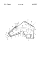
- the infrared radiation thermometer as illustrated in the drawing has an angled housing 1 with a forward housing section 2 and a rear housing section 3.
- the forward housing section 2 which tapers conically in the direction of a radiation inlet 23 has on its radiation inlet 23 a window 4 that is covered with a probe cover 5 for measurement.
- the rear area of the probe cover 5 is dimensioned such as to be suitable for insertion in a person's ear canal (not shown) for taking a temperature reading without exerting a high pressure on the ear--and this in both an adult's or a child's ear canal.
- the probe cover 5 is a thin polyethylene film extending in particular over the window 4 and being transparent to infrared radiation for taking a person's temperature.
- thermometer For storage of the thermometer, it is possible either to place a protective cap 6 onto the probe cover 5 as shown in the Figure, or to place directly on the housing section 2 (not shown) a protective cap 6 (without probe cover) which has a small spacing to the probe cover in its interior to avoid contamination. However, it can also be considered to store the instrument with just the probe cover 5 mounted.
- an infrared sensor 8 is arranged in the rear housing section 3. To direct the radiation passing through the window 4 into the interior of the housing 1 to the infrared sensor 8, a reflective device 9 is secured to a rear housing wall 10.
- the infrared sensor 8 is preferably configured as a pyroelectric sensor. In a further embodiment, the infrared sensor 8 is configured as a thermopile sensor.
- the infrared window 4 is selected such that infrared radiation identified by arrows 22 enters the housing 1 in the wave-length range relevant for the temperature. At room temperature, this range is between 5 ⁇ m and 15 ⁇ m.
- a window 4 is manufactured from a sheet of polyethylene, for example.
- the probe 5 serves as protective film for the window 4, being fitted prior to each temperature measurement and removed again subsequent to each measurement to prevent a used probe cover 5 from being used again by another person.
- the probe cover 5 maintains the area of the forward housing section 2 of the infrared thermometer in a sanitary condition.
- the probe cover 5 which covers the window 4 or, in the event of no window 4 existing, closes off the interior of the housing 1, serves to protect the corresponding optical components from contamination. Contamination may be attributable to dust, dirt or the effect of humidity on the one hand, and ear wax on the other hand.
- a net probe cover 5 for a used probe cover 5
- another person does not have to introduce a contaminated probe cover 5 into his or her ear canal.
- the probe cover 5 is readily replaceable by being pulled off the forward housing section 2 and substituting a new probe cover 5.
- the robe cover 5 is designed to be a disposable item, a new one being used for each temperature measurement.
- the instrument is not ready for operation until after a predetermined period of time. This involves the release of a warning signal 14 not until after a predetermined, where applicable, adjustable delay interval if the instrument is to be used without a probe cover or with the same probe cover. For this purpose, delay intervals from three to five seconds, for example, are sufficient. If the absence of the probe cover 5 continues to be established upon the expiration of such a delay interval, the first warning signal 14 will be generated, telling the user that a probe cover 5 should be fitted over the IR window 4 or the forward housing section 2.
- annular stop 24 is provided on the forward housing section 2 for abutting engagement with an end section 12 of the probe cover 5.
- This annular stop 24 has an electric switching device 15 which on abutment of the probe cover 5 is closed by the probe cover's annular collar 16, whereby an electric signal is generated which is supplied via leads 25 to an evaluation unit 13, not shown in greater detail, which is electrically connected to the infrared sensor 8.
- the switching device 15 has its one contact tab 17 connected to a slidable tappet 18 which is displaced by the annular collar 16 when the probe cover 5 is installed and connects the contact tab 17 to the contact tab 29, that is, short-circuits the switching device 15 to thereby produce an electric signal by means of which neither the signal lamp 14 nor an audible signal (not shown) is released.
- the switching device 15 is preferably a microswitch. It will be understood, however, that a magnetic switch or a further optical sensor may be substituted producing equally an electric signal when the probe cover 5 is mounted.
- the warning signal is a visual or audible signal, for example, a light-emitting diode 14 as shown in the Figure, or a piezoelectric buzzer (not shown).
- the lamp is of such brightness that an operator will see it also when the sun shines, being thus alerted to the absence of a probe cover 5.
- the electric switching device 15 in this embodiment will not cause the electric signal for "probe cover installed" to be produced in the evaluation unit 13, as a result of which the lamp or light-emitting diode 14 lights up or flashes clearly.
- This informs an operator that no probe cover 5 is fitted over the housing section 2 or that the probe cover 5 is not in proper seating engagement with the forward cylindrical housing section 2, so that no proper temperature reading takes place.
- a further warning signal 11 which is generated by the evaluation unit 13 and is, for example, also configured to be a light-emitting diode, will be issued.
- the light-emitting diode 11 signals to the operator that a measurement was performed within the range of body temperature but without probe cover 5, providing, in addition to the information that the measured value is not correct, the information that the IR window 4 needs to be cleaned, in order to avoid that error is introduced in a subsequent temperature measurement taken with the probe cover 5, for example.
- a warning signal 11 will be issued also if a sensible temperature value greater than 36.5° C., for example, was measured, but without using a new probe cover 5.
- the warning signal 11 indicates that the electric switching device 15 has not detected a replaced probe cover, and that hence sanitary conditions may be doubtful or erroneous readings may have occurred due to a contaminated probe cover.
- the warning signal 11 indicating that a probe cover 5 has been used several times is issued by a third device.
- This third device is configured, for example, as a third light-emitting diode or a third type of signal, so that a distinction is possible from the warning signal 11 indicative of a temperature measurement within the range of body temperature with the probe cover 5 not installed.
- the electric switching device 15 is coupled to the On/Off function of the infrared radiation thermometer, causing the instrument to turn itself on automatically as the protective cap 6 is removed. In this arrangement, the electric switching device 15 detects the presence of both the protective cap 6 and the probe cover 5.
- a second embodiment makes provision for two sensors which operate independently of each other to detect the presence of the probe cover and the protective cap.
- the sensor or electric switching device (not illustrated in the Figure) for detecting the presence of the protective cap 6 is at the same time connected to an On/Off switch of the instrument, so that the instrument is turned on when the protective cap 6 is removed.
- an electrical connection is provided between the sensor for the protective cap 6 and the evaluation unit 13 by means of which the sensor delivers to the evaluation unit 13 an electric signal which after a predetermined interval activates a further warning signal to indicate an error condition on the radiation inlet (soiled), on the probe cover 5 (absent or used several times), or a missing protective cap 6. This is necessary to prevent the unprotected IR window 4 from contamination or damage during storage. Where separate sensors are provided for the protective cap 6 and the probe cover 5, different time intervals are set until a warning signal is released.
- a further embodiment makes provision for a power save mode enabling a temperature measurement to be automatically performed continually or at short intervals. If a temperature reading is then taken which is within the range of body temperature although no probe cover 5 is installed or a measurement within the range of body temperature was already performed with the probe cover installed, the evaluation unit 13 will generate a warning signal 11.
Applications Claiming Priority (3)
| Application Number | Priority Date | Filing Date | Title |
|---|---|---|---|
| DE19543096 | 1995-11-18 | ||
| DE19543096A DE19543096C2 (de) | 1995-11-18 | 1995-11-18 | Infrarot-Strahlungsthermometer |
| PCT/EP1996/004933 WO1997019332A1 (de) | 1995-11-18 | 1996-11-12 | Infrarot-strahlungsthermometer |
Publications (1)
| Publication Number | Publication Date |
|---|---|
| US6149297A true US6149297A (en) | 2000-11-21 |
Family
ID=7777835
Family Applications (1)
| Application Number | Title | Priority Date | Filing Date |
|---|---|---|---|
| US09/068,840 Expired - Fee Related US6149297A (en) | 1995-11-18 | 1996-11-12 | Infrared radiation thermometer |
Country Status (10)
| Country | Link |
|---|---|
| US (1) | US6149297A (de) |
| EP (1) | EP0861424B1 (de) |
| JP (1) | JP2000504947A (de) |
| CN (1) | CN1081324C (de) |
| AT (1) | ATE206517T1 (de) |
| DE (2) | DE19543096C2 (de) |
| DK (1) | DK0861424T3 (de) |
| ES (1) | ES2165528T3 (de) |
| HK (1) | HK1016256A1 (de) |
| WO (1) | WO1997019332A1 (de) |
Cited By (26)
| Publication number | Priority date | Publication date | Assignee | Title |
|---|---|---|---|---|
| US6336742B2 (en) * | 1997-08-08 | 2002-01-08 | Omron Corporation | Clinical thermometer for receiving infrared radiation from a human eardrum |
| US6584426B2 (en) * | 1998-10-28 | 2003-06-24 | Omron Corporation | Electronic thermometer |
| US6612735B2 (en) * | 2001-06-01 | 2003-09-02 | Omron Corporation | Infrared ray clinical thermometer |
| US6626568B2 (en) * | 2000-06-09 | 2003-09-30 | Omxon Corporation | Radiation clinical thermometer and method of measuring body temperature using the radiation clinical thermometer |
| US6647284B1 (en) * | 2002-09-16 | 2003-11-11 | Oriental System Technology Inc. | Probe cover of a tympanic thermometer and tympanic thermometer assembly |
| EP1391178A1 (de) | 2002-08-23 | 2004-02-25 | Hewlett-Packard Development Company, L.P. | Biosensor zur Messung der kardiopulmonalen Aktivität und Verfahren zu seiner Verwendung |
| US20040095985A1 (en) * | 2002-11-15 | 2004-05-20 | Ko Kun Yuan | Dual-use infrared thermometer |
| WO2004043256A2 (en) * | 2002-11-12 | 2004-05-27 | Prourocare, Inc. | Intelligent medical device barrier |
| US6789936B1 (en) * | 1999-06-28 | 2004-09-14 | Braun Gmbh | Infrared thermometer for performing temperature measurements at different sites |
| US20040240516A1 (en) * | 2002-12-12 | 2004-12-02 | James Harr | Thermal tympanic thermometer tip |
| US6886978B2 (en) * | 2001-06-18 | 2005-05-03 | Omron Corporation | Electronic clinical thermometer |
| US6890096B2 (en) * | 2001-04-11 | 2005-05-10 | Omron Corporation | Electronic clinical thermometer |
| US7434991B2 (en) | 2002-12-12 | 2008-10-14 | Covidien Ag | Thermal tympanic thermometer |
| US20090159589A1 (en) * | 2006-05-19 | 2009-06-25 | Bsh Bosch Und Siemens Hausgerate Gmbh | Household Appliance, Preferably Cooking Hob |
| US20100017163A1 (en) * | 2007-03-26 | 2010-01-21 | Terumo Kabushiki Kaisha | Ear-type thermometer and a control method thereof |
| US20100329305A1 (en) * | 2009-06-30 | 2010-12-30 | Edan Instruments, Inc. | Induction Type of Electronic Thermometer Probe Motion Detection Device |
| US20110110395A1 (en) * | 2009-10-05 | 2011-05-12 | Jacob Fraden | Multi-site attachments for ear thermometers |
| US20110194585A1 (en) * | 2010-02-09 | 2011-08-11 | Abhishek Shrivastava | Multiple object non-contact thermometer |
| US20110228810A1 (en) * | 2010-02-09 | 2011-09-22 | O'hara Gary | Multiple object talking non-contact thermometer |
| US20110305257A1 (en) * | 2010-06-10 | 2011-12-15 | Avita Corporation | Temperature Measuring Apparatus |
| US8292500B1 (en) | 2011-09-30 | 2012-10-23 | Tyco Healthcare Group Lp | IR sensor for electronic thermometer |
| EP2574889A1 (de) * | 2011-09-30 | 2013-04-03 | Covidien LP | Kapazitiver Sensor für Thermometer |
| US20140254626A1 (en) * | 2010-07-08 | 2014-09-11 | Cvg Management Corporation | Infrared temperature measurement and stabilization thereof |
| US20150071457A1 (en) * | 2013-09-12 | 2015-03-12 | Sony Corporation | Bluetooth earplugs |
| US9357930B2 (en) | 2012-03-19 | 2016-06-07 | Welch Allyn, Inc. | Temperature measurement system |
| US20180266888A1 (en) * | 2010-07-08 | 2018-09-20 | Cvg Management Corporation | Infrared temperature measurement and stabilization thereof |
Families Citing this family (9)
| Publication number | Priority date | Publication date | Assignee | Title |
|---|---|---|---|---|
| CN1329718C (zh) * | 2003-04-20 | 2007-08-01 | 深圳清华大学研究院 | 非接触红外手掌表面温度快速检测方法和仪器 |
| CN1329716C (zh) * | 2003-04-20 | 2007-08-01 | 深圳清华大学研究院 | 扫描式非接触红外体温检测仪器及体温检测方法 |
| CN1329717C (zh) * | 2003-04-20 | 2007-08-01 | 深圳清华大学研究院 | 定位式非接触红外体温检测仪器和体温检测方法 |
| US8876373B2 (en) | 2009-04-09 | 2014-11-04 | Welch Allyn, Inc. | IR thermometry probe cover |
| USD787683S1 (en) | 2009-04-09 | 2017-05-23 | Welch Allyn, Inc. | Cover for a probe |
| CN102648843A (zh) * | 2012-04-26 | 2012-08-29 | 深圳市东迪欣科技有限公司 | 一种红外体温计及其清洁提示方法 |
| CN102743161B (zh) * | 2012-05-08 | 2015-08-19 | 深圳市东迪欣科技有限公司 | 一种红外体温计及其提示方法 |
| AT512978B1 (de) * | 2012-06-08 | 2015-10-15 | Hagl Peter Dipl Ing | Abdeckkappe, Messgerät mit Abdeckkappe und Verfahren zur Herstellung einer Abdeckkappe |
| TWI731795B (zh) * | 2020-09-25 | 2021-06-21 | 熱映光電股份有限公司 | 紅外線感測模組與額溫量測裝置 |
Citations (9)
| Publication number | Priority date | Publication date | Assignee | Title |
|---|---|---|---|---|
| EP0024717A2 (de) * | 1979-08-29 | 1981-03-11 | Thomas Trunz | Temperaturmessfühler |
| EP0445784A2 (de) * | 1990-03-08 | 1991-09-11 | Ivac Corporation | Schutzvorrichtung für eine biomedizinische Sonde |
| EP0472490A1 (de) * | 1990-08-24 | 1992-02-26 | Thermoscan Inc. | Einteilige Sondenabdeckung |
| EP0502277A2 (de) * | 1991-03-04 | 1992-09-09 | Pat O. Daily Revocable Trust | Ohrthermometer mit Faseroptik |
| US5169235A (en) * | 1990-08-30 | 1992-12-08 | Hirose Electric Co., Ltd. | Radiation type thermometer |
| EP0565123A1 (de) * | 1992-04-08 | 1993-10-13 | Omron Corporation | Klinisches Strahlungsthermometer |
| US5340215A (en) * | 1990-12-29 | 1994-08-23 | Omron Corporation | Radiant-energy clinical thermometer |
| WO1995000067A1 (en) * | 1993-06-18 | 1995-01-05 | Infra-Temp, Inc. | Electronic thermometer probe cover |
| US5487607A (en) * | 1992-04-08 | 1996-01-30 | Omron Corporation | Radiation clinical thermometer |
-
1995
- 1995-11-18 DE DE19543096A patent/DE19543096C2/de not_active Expired - Fee Related
-
1996
- 1996-11-12 EP EP96938175A patent/EP0861424B1/de not_active Expired - Lifetime
- 1996-11-12 DK DK96938175T patent/DK0861424T3/da active
- 1996-11-12 JP JP9519347A patent/JP2000504947A/ja not_active Ceased
- 1996-11-12 WO PCT/EP1996/004933 patent/WO1997019332A1/de active IP Right Grant
- 1996-11-12 US US09/068,840 patent/US6149297A/en not_active Expired - Fee Related
- 1996-11-12 DE DE59607844T patent/DE59607844D1/de not_active Expired - Lifetime
- 1996-11-12 CN CN96198346A patent/CN1081324C/zh not_active Expired - Fee Related
- 1996-11-12 ES ES96938175T patent/ES2165528T3/es not_active Expired - Lifetime
- 1996-11-12 AT AT96938175T patent/ATE206517T1/de not_active IP Right Cessation
-
1999
- 1999-03-31 HK HK99101332A patent/HK1016256A1/xx not_active IP Right Cessation
Patent Citations (10)
| Publication number | Priority date | Publication date | Assignee | Title |
|---|---|---|---|---|
| EP0024717A2 (de) * | 1979-08-29 | 1981-03-11 | Thomas Trunz | Temperaturmessfühler |
| EP0445784A2 (de) * | 1990-03-08 | 1991-09-11 | Ivac Corporation | Schutzvorrichtung für eine biomedizinische Sonde |
| EP0472490A1 (de) * | 1990-08-24 | 1992-02-26 | Thermoscan Inc. | Einteilige Sondenabdeckung |
| US5169235A (en) * | 1990-08-30 | 1992-12-08 | Hirose Electric Co., Ltd. | Radiation type thermometer |
| US5340215A (en) * | 1990-12-29 | 1994-08-23 | Omron Corporation | Radiant-energy clinical thermometer |
| EP0502277A2 (de) * | 1991-03-04 | 1992-09-09 | Pat O. Daily Revocable Trust | Ohrthermometer mit Faseroptik |
| EP0565123A1 (de) * | 1992-04-08 | 1993-10-13 | Omron Corporation | Klinisches Strahlungsthermometer |
| US5487607A (en) * | 1992-04-08 | 1996-01-30 | Omron Corporation | Radiation clinical thermometer |
| WO1995000067A1 (en) * | 1993-06-18 | 1995-01-05 | Infra-Temp, Inc. | Electronic thermometer probe cover |
| US5411032A (en) * | 1993-06-18 | 1995-05-02 | Infra-Temp Inc. | Electronic thermometer probe cover |
Cited By (44)
| Publication number | Priority date | Publication date | Assignee | Title |
|---|---|---|---|---|
| US6336742B2 (en) * | 1997-08-08 | 2002-01-08 | Omron Corporation | Clinical thermometer for receiving infrared radiation from a human eardrum |
| US6584426B2 (en) * | 1998-10-28 | 2003-06-24 | Omron Corporation | Electronic thermometer |
| US6789936B1 (en) * | 1999-06-28 | 2004-09-14 | Braun Gmbh | Infrared thermometer for performing temperature measurements at different sites |
| US6626568B2 (en) * | 2000-06-09 | 2003-09-30 | Omxon Corporation | Radiation clinical thermometer and method of measuring body temperature using the radiation clinical thermometer |
| US7284904B2 (en) | 2001-04-11 | 2007-10-23 | Omron Corporation | Electronic clinical thermometer |
| US7059767B2 (en) | 2001-04-11 | 2006-06-13 | Omron Corporation | Electronic clinical thermometer |
| US6890096B2 (en) * | 2001-04-11 | 2005-05-10 | Omron Corporation | Electronic clinical thermometer |
| US6612735B2 (en) * | 2001-06-01 | 2003-09-02 | Omron Corporation | Infrared ray clinical thermometer |
| US6886978B2 (en) * | 2001-06-18 | 2005-05-03 | Omron Corporation | Electronic clinical thermometer |
| EP1391178A1 (de) | 2002-08-23 | 2004-02-25 | Hewlett-Packard Development Company, L.P. | Biosensor zur Messung der kardiopulmonalen Aktivität und Verfahren zu seiner Verwendung |
| EP1588662A2 (de) | 2002-08-23 | 2005-10-26 | Hewlett-Packard Development Company, L.P. | Biosensor zur Messung der kardiopulmonalen Aktivität und Verfahren zu seiner Verwendung |
| US6647284B1 (en) * | 2002-09-16 | 2003-11-11 | Oriental System Technology Inc. | Probe cover of a tympanic thermometer and tympanic thermometer assembly |
| US20040231772A1 (en) * | 2002-11-12 | 2004-11-25 | Leonard Todd E. | Intelligent medical device barrier |
| WO2004043256A3 (en) * | 2002-11-12 | 2004-07-01 | Prourocare Inc | Intelligent medical device barrier |
| WO2004043256A2 (en) * | 2002-11-12 | 2004-05-27 | Prourocare, Inc. | Intelligent medical device barrier |
| US20040095985A1 (en) * | 2002-11-15 | 2004-05-20 | Ko Kun Yuan | Dual-use infrared thermometer |
| US7108419B2 (en) | 2002-12-12 | 2006-09-19 | Sherwood Services Ag | Thermal tympanic thermometer tip |
| US7434991B2 (en) | 2002-12-12 | 2008-10-14 | Covidien Ag | Thermal tympanic thermometer |
| US7841767B2 (en) | 2002-12-12 | 2010-11-30 | Covidien Ag | Thermal tympanic thermometer |
| US20040240516A1 (en) * | 2002-12-12 | 2004-12-02 | James Harr | Thermal tympanic thermometer tip |
| US20090159589A1 (en) * | 2006-05-19 | 2009-06-25 | Bsh Bosch Und Siemens Hausgerate Gmbh | Household Appliance, Preferably Cooking Hob |
| US8126672B2 (en) * | 2007-03-26 | 2012-02-28 | Terumo Kabushiki Kaisha | Ear-type thermometer and a control method thereof |
| US20100017163A1 (en) * | 2007-03-26 | 2010-01-21 | Terumo Kabushiki Kaisha | Ear-type thermometer and a control method thereof |
| US20100329305A1 (en) * | 2009-06-30 | 2010-12-30 | Edan Instruments, Inc. | Induction Type of Electronic Thermometer Probe Motion Detection Device |
| US8256955B2 (en) * | 2009-06-30 | 2012-09-04 | Edan Instruments, Inc. | Induction type of electronic thermometer probe motion detection device |
| US8517603B2 (en) * | 2009-10-05 | 2013-08-27 | Kaz Usa, Inc. | Multi-site attachments for ear thermometers |
| US20110110395A1 (en) * | 2009-10-05 | 2011-05-12 | Jacob Fraden | Multi-site attachments for ear thermometers |
| US20110194585A1 (en) * | 2010-02-09 | 2011-08-11 | Abhishek Shrivastava | Multiple object non-contact thermometer |
| US20110228810A1 (en) * | 2010-02-09 | 2011-09-22 | O'hara Gary | Multiple object talking non-contact thermometer |
| US8371748B2 (en) * | 2010-06-10 | 2013-02-12 | Avita Corporation | Temperature measuring apparatus |
| US20110305257A1 (en) * | 2010-06-10 | 2011-12-15 | Avita Corporation | Temperature Measuring Apparatus |
| US9228902B2 (en) * | 2010-07-08 | 2016-01-05 | Cvg Management Corporation | Infrared temperature measurement and stabilization thereof |
| US10782187B2 (en) * | 2010-07-08 | 2020-09-22 | Cvg Management Corporation | Infrared temperature measurement and stabilization thereof |
| US10260954B2 (en) * | 2010-07-08 | 2019-04-16 | Cvg Management Corporation | Infrared temperature measurement and stabilization thereof |
| US20140254626A1 (en) * | 2010-07-08 | 2014-09-11 | Cvg Management Corporation | Infrared temperature measurement and stabilization thereof |
| US20180266888A1 (en) * | 2010-07-08 | 2018-09-20 | Cvg Management Corporation | Infrared temperature measurement and stabilization thereof |
| US20170122811A1 (en) * | 2010-07-08 | 2017-05-04 | Cvg Management Corporation | Infrared temperature measurement and stabilization thereof |
| US8292500B1 (en) | 2011-09-30 | 2012-10-23 | Tyco Healthcare Group Lp | IR sensor for electronic thermometer |
| US8949065B2 (en) | 2011-09-30 | 2015-02-03 | Covidien Lp | Capacitive sensor for thermometer probe |
| US8622613B2 (en) | 2011-09-30 | 2014-01-07 | Covidien Lp | IR sensor for electronic thermometer |
| EP2574889A1 (de) * | 2011-09-30 | 2013-04-03 | Covidien LP | Kapazitiver Sensor für Thermometer |
| US9357930B2 (en) | 2012-03-19 | 2016-06-07 | Welch Allyn, Inc. | Temperature measurement system |
| US9351063B2 (en) * | 2013-09-12 | 2016-05-24 | Sony Corporation | Bluetooth earplugs |
| US20150071457A1 (en) * | 2013-09-12 | 2015-03-12 | Sony Corporation | Bluetooth earplugs |
Also Published As
| Publication number | Publication date |
|---|---|
| DE19543096A1 (de) | 1997-05-22 |
| ATE206517T1 (de) | 2001-10-15 |
| DE19543096C2 (de) | 1998-07-23 |
| WO1997019332A1 (de) | 1997-05-29 |
| EP0861424B1 (de) | 2001-10-04 |
| EP0861424A1 (de) | 1998-09-02 |
| CN1202243A (zh) | 1998-12-16 |
| ES2165528T3 (es) | 2002-03-16 |
| CN1081324C (zh) | 2002-03-20 |
| JP2000504947A (ja) | 2000-04-25 |
| DK0861424T3 (da) | 2002-01-28 |
| DE59607844D1 (de) | 2001-11-08 |
| HK1016256A1 (en) | 1999-10-29 |
Similar Documents
| Publication | Publication Date | Title |
|---|---|---|
| US6149297A (en) | Infrared radiation thermometer | |
| US6195581B1 (en) | Process for evaluating the signal of an infrared thermometer, and infrared thermometer | |
| US8374683B2 (en) | Medical instrument with probe, probe cover, and methods of using the same | |
| EP1549922B1 (de) | Versiegelte sondenkammer für eine thermometrievorrichtung | |
| US20130083823A1 (en) | Electronic thermometer with image sensor and display | |
| EP0180368A2 (de) | Verfahren und Vorrichtung zur Messung der inneren Körpertemperatur mit Verwendung der Infrarotausstrahlung | |
| JP2001029317A (ja) | 様々な部位の温度測定用の赤外線温度計 | |
| US20020181545A1 (en) | Electronic thermometer | |
| EP1037556A1 (de) | Schutzschale für infrarotthermometer mit zwei positionen | |
| WO1998001730A1 (en) | Infrared thermometer comprising optical aiming system | |
| US8949065B2 (en) | Capacitive sensor for thermometer probe | |
| KR20110070321A (ko) | 적외선 이마 체온 측정 장치 | |
| US20060120432A1 (en) | Tympanic thermometer with ejection mechanism | |
| JP2993103B2 (ja) | 非接触口腔用体温計 | |
| EP1581786A1 (de) | Tympanisches thermometer mit auswurfmechanismus | |
| JPH1119048A (ja) | 放射体温計 | |
| US8292500B1 (en) | IR sensor for electronic thermometer | |
| AU2002252558B2 (en) | Electronic thermometer | |
| AU2002252558A1 (en) | Electronic thermometer |
Legal Events
| Date | Code | Title | Description |
|---|---|---|---|
| AS | Assignment |
Owner name: BRAUN AKTIENGESELLSCHAFT, GERMANY Free format text: ;ASSIGNORS:BEERWERTH, FRANK;JESTADT, ALBRECHT;BULTGES, HEINZ;REEL/FRAME:009229/0311 Effective date: 19980513 |
|
| AS | Assignment |
Owner name: BRAUN AKTIENGESELLSCHAFT, GERMANY Free format text: ASSIGNMENT OF ASSIGNORS INTEREST;ASSIGNORS:BEERWERTH, FRANK;JESTADT, ALBRECHT;BULTGES, HEINZ;REEL/FRAME:009232/0499 Effective date: 19980513 |
|
| AS | Assignment |
Owner name: BRAUN GMBH, GERMANY Free format text: CHANGE OF NAME;ASSIGNOR:BRAUN AKTIENGESELLSCHAFT;REEL/FRAME:010654/0006 Effective date: 19990901 |
|
| REMI | Maintenance fee reminder mailed | ||
| LAPS | Lapse for failure to pay maintenance fees | ||
| STCH | Information on status: patent discontinuation |
Free format text: PATENT EXPIRED DUE TO NONPAYMENT OF MAINTENANCE FEES UNDER 37 CFR 1.362 |
|
| FP | Lapsed due to failure to pay maintenance fee |
Effective date: 20041121 |