US6149225A - Self adjusting roof mounting for a pop-up camper - Google Patents
Self adjusting roof mounting for a pop-up camper Download PDFInfo
- Publication number
- US6149225A US6149225A US09/014,645 US1464598A US6149225A US 6149225 A US6149225 A US 6149225A US 1464598 A US1464598 A US 1464598A US 6149225 A US6149225 A US 6149225A
- Authority
- US
- United States
- Prior art keywords
- roof
- posts
- camper
- pop
- guide block
- Prior art date
- Legal status (The legal status is an assumption and is not a legal conclusion. Google has not performed a legal analysis and makes no representation as to the accuracy of the status listed.)
- Expired - Fee Related
Links
Images


Classifications
-
- B—PERFORMING OPERATIONS; TRANSPORTING
- B60—VEHICLES IN GENERAL
- B60P—VEHICLES ADAPTED FOR LOAD TRANSPORTATION OR TO TRANSPORT, TO CARRY, OR TO COMPRISE SPECIAL LOADS OR OBJECTS
- B60P3/00—Vehicles adapted to transport, to carry or to comprise special loads or objects
- B60P3/32—Vehicles adapted to transport, to carry or to comprise special loads or objects comprising living accommodation for people, e.g. caravans, camping, or like vehicles
- B60P3/34—Vehicles adapted to transport, to carry or to comprise special loads or objects comprising living accommodation for people, e.g. caravans, camping, or like vehicles the living accommodation being expansible, collapsible or capable of rearrangement
- B60P3/341—Vehicles adapted to transport, to carry or to comprise special loads or objects comprising living accommodation for people, e.g. caravans, camping, or like vehicles the living accommodation being expansible, collapsible or capable of rearrangement comprising flexible elements
Definitions
- the invention relates to pop-up campers pulled on trailers or directly mounted in trucks. More specifically, the invention involves the mounting of a roof on the telescopic support posts of a pop-up camper.
- Pop-up campers are designed as small trailers or truck compartments which in their collapsed form can be transported by hitching the pop-up camper to a vehicle in the case of a trailer, or by securing the camper in the bed of the truck. Such campers are used for recreational camping in a variety of environments ranging from desert heat to sub-freezing conditions.
- Pop-up campers conventionally include an aluminum and/or wood body which has a floor and interior cabinets, tables, and benches surrounded by tent-like side walls when the roof is raised. When stationary, the pop-up camper may be deployed to provide living quarters for camping enthusiasts. In order to deploy the pop-up camper, the roof must be raised and tent panels extended so that the interior space is completely extended.
- Pop-up campers conventionally utilize telescopic support posts as part of a lifting system to support and lift a roof over the camper body.
- telescopic support is disclosed in U.S. Pat. No. 4,299,421, assigned to the assignee of the present invention, the disclosure of which is incorporated by reference herein.
- the telescopic support posts should be aligned directly with mounting locations on the roof so that the force imparted by the lifting mechanism, e.g. a hand crank or electric motor, is sufficient to raise the posts.
- the lifting mechanism e.g. a hand crank or electric motor
- an aluminum camper body may expand significantly less than a polymer formed roof over a temperature swing, which can vary from -40° to 140° in ambient conditions, e.g., one quarter inch (1/4") to one inch (1") depending on the direction of measurement.
- the mounting locations of the support posts relative to the body may then vary according to the temperature.
- the temperature at the time of deployment may create a misalignment using conventional attaching methods.
- the one quarter (1/4) to one and one quarter (11/4) inch differential may only be barely noticeable visually, but such a differential may create a critical misalignment and binding of the telescopic lifting system. Further binding of the system when closed may place excessive loads and stresses on the roof, lifter posts, or camper body leading to damage.
- the inventional pop-up camper includes an adjustable mounting location for the roof lifting system.
- the adjustable mountings allow the roof to thermally expand or contract without effecting the location of the roof relative to the lifting system.
- the invention comprises a pop-up camper having a body, a roof, a lifting system, and the adjustable mountings.
- the lifting system is located within the body and is attached to the roof at a plurality of mounting positions.
- the lifting system also includes a plurality of retractable posts adapted to extend in a direction along the axial centers of the posts. In their extended position, the posts support the roof over the body.
- the adjustable mountings on the roof adjust the location of the mounting positions relative to the roof. This allows the mounting positions to be maintained in alignment with the axial centers of the posts of the lifting system. The posts thereby remain properly aligned with the mounting positions regardless of a differential thermal expansion or contraction of the roof relative the body.
- the invention comprises a roof for a pop-up camper having such adjustable mountings to adjust the location of the mounting positions of relative to the roof.
- Existing camper lifting systems can be retrofitted to connect to the adjustable mountings so that a new roof made of materials with different thermal expansion properties than existing campers can be used on those campers.
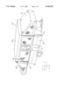
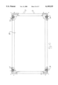
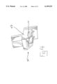
- FIG. 1 is a perspective view of the pop-up camper of the present invention in the extended position.
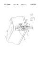
- FIG. 2 is a perspective view of the adjustable roof mounting of the present invention.
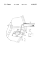
- FIG. 3 is a an exploded view of FIG. 2.
- FIG. 4 is a perspective view of an alternative embodiment of a component of the adjustable roof mounting.
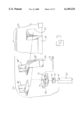
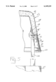
- FIG. 5 is a side sectional view of the adjustable roof mounting, while FIG. 5a is a top plan sectional view of FIG. 5.
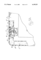
- FIG. 6 is a side sectional view of the adjustable roof mounting with the roof in an contracted state, while FIG. 6a is a top plan sectional view of FIG. 6.
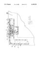
- FIG. 7 is a side sectional view of the adjustable roof mounting with the roof in an expanded state, while FIG. 7a is a top plan sectional view of FIG. 7.
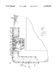
- FIG. 8 is a bottom plan view in partial cut-away of the roof.
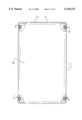
- FIG. 9 is a bottom plan view in partial cut-away of the roof in a contracted position.
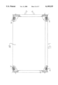
- FIG. 10 is a bottom plan view in partial cut-away of the roof in an expanded position.
- FIG. 11 is a bottom plan view in partial cut-away of a second alternative embodiment of the roof mounting system.
- FIG. 12 is a perspective view of the roof mounting system of FIG. 11.
- FIG. 13 is a bottom plan view in partial cut-away of a third alternative embodiment of the roof mounting system.
- FIG. 14 is a perspective view of the roof mounting system of FIG. 13.
- FIG. 1 shows camper 20 in a deployed condition.
- Roof 22 depicted as having a body in the form of a shell, is supported over camper body 24 by a plurality of retractable support posts 26, in this embodiment four posts 26 are disposed at the four comers of the generally rectangular configuration of camper body 24.
- Each retractable support post 26 actually includes a plurality of telescoping post segments, which may have a square, rectangular, round, etc. outer contour.
- Posts 26 fit within body 24 in the retracted arrangement, wherein roof 22 is disposed directly on top of camper body 24.
- Roof 22 is extended to the position of FIG. 1 by operation of a lifting system (not shown) which is adapted to urge support posts 26 upward and allow deployment of side panels 28, sleeper extensions 30, and door 32 between roof 22 and camper body 24.
- the locations where support posts 26 are mounted to roof 22 should be maintained in alignment with the axial center of posts 26.
- roof 22 and camper body 24 are made of the same material, e.g. aluminum, then the resistance of retractable support posts 26 remains minimal as long as posts 26 are properly aligned relative to the mounting positions of roof 22 at manufacture.
- roof 24 is made of a different material than camper body 24, a material having different thermal coefficients of expansion and contraction, then fixed mounting of posts 26 could result in an expanded or contracted roof 24 positioning a fixed mounting out of alignment with the axial centers of posts 26.
- posts 26 are connected to roof 22 by adjustable mounting arrangement 34, see FIGS. 2 and 3.
- the upper end of post 26 includes hole 36 and an axial chamber (not shown in FIGS. 2 and 3) which receives end plug 38 which has hole 40 located in a corresponding position to hole 36.
- Holes 36 and 40 receive rod 42 which is slidably supported within channel 44 of guide block 46.
- the upper surface of end plug 38 may also slide on the lower surface of block 46.
- Block 46 is attached to mounting bracket 48 which is affixed to the bottom surface of roof 22.
- Mounting bracket 48 is shown in two alternative embodiments in FIG. 3.
- the embodiment of mounting bracket 48' has a lower end which simply connects with the upper portion of guide bracket 46.
- the embodiment of mounting bracket 48" has lower extension 50 which reaches the bottom edge of roof 22.
- Lower extension 50 includes a thicken portion 52 having a thickness which approximately equals the extra thickness of lip portion 54 of roof 22 compared to the thickness of indentation portion 56 of roof 22.
- Indentation portion 56 is created as a result of the manufacturing process of an ABS article needing a recess, and consequently the bottom portion of roof 22 cannot have a uniform thickness for registering and sealing purposes.
- the bottom portion of roof 22 may have a uniform apparent thickness.
- FIGS. 5, 5a, and 8 show roof 22 in a normative position, that is when its temperature is such that its size generally corresponds to the size of camper body 24.
- posts 26 are generally aligned with their axes located around the center of guide block 46, see FIG. 8.
- End plug 38 rests against slide surface 58 of bracket 48", which in turn is attached to interior shell 58 of roof 22, see FIGS. 5 and 5a.
- Roof 22 also includes outer shell 60 and foam material 62 disposed between shells 58 and 60. Inner shell 58 and outer shell 60 also abut in the region of indentation portion 56, thus requiring thickened portion 52 to provide a uniform apparent thickness to facilitate the engagement of bottom seal 64, in this embodiment a bulb seal.
- bottom seal 64 forms a fluid repellant barrier between roof 22 and camper body 24 to protect the interior component of camper 20.
- FIG. 9 shows how roof 22 may contract in relation to camper body 24, thus resulting in guide blocks 46 moving relative to posts 26.
- This inward contraction and movement of roof 22 does not effect the position of posts 26, as the sliding engagement of end plug 38 and guide block 46 allows rod 42 to move within channel 44, while the internal configuration of block 46, which includes guide walls 66, directs the movement of guide block 46, and its attached roof 22, relative to posts 26.
- Rod 42 retains posts 26 with roof 22 while allowing for the contraction movement of roof 22.
- the shape and relative configuration of guide walls 66 of all four mountings 34 serve to keep roof 22 approximately centered over camper body 24.
- FIG. 10 shows how roof 22 may expand in relation to camper body 24, thus resulting in guide blocks 46 moving relative to posts 26.
- This outward expansion and movement of roof 22 does not effect the position of posts 26, as the sliding engagement of end plug 38 and guide block 46 allows rod 42 to move within channel 44, while the internal configuration of block 46, which includes guide walls 66, directs the relative movement of guide block 46, and its attached roof 22, and posts 26.
- Rod 42 retains posts 26 with roof 22 while allowing for the expansion movement of roof 22.
- FIG. 4 shows an alternative embodiment of mounting arrangement 34' which combines the structures of guide block 46 and mounting bracket 48 in the form of unitary guide bracket 47.
- Guide bracket 47 includes channel 44' for slidably receiving rod 42, with the underside of guide bracket 47 having a similar configuration to the underside of guide block 46 and the surface engaging roof 22 matching the corresponding surface of mounting bracket 48. While the embodiment of FIG. 4 shows guide bracket 47 having a configuration corresponding to mounting bracket 48' of FIG. 3, alternatively guide bracket 47 could have a configuration which corresponds to mounting bracket 48" of FIG. 3.
- FIGS. 11-14 show further alternative embodiments of mounting arrangements according to the present invention.
- FIGS. 11-12 depict mounting arrangement 34", wherein guide block 120 includes channel 122 which accepts post cap 124.
- post cap 124 is attached to the upper portion of post 26 so that rider 128 engages channel 122 and constrains the movement of post 26 to be in the direction of channel 122.
- Guide block 120 is shown attached to the corner of roof 22, although guide block 120 could alternatively be disposed at an angle from a side of roof 22.
- guide blocks 120 of mounting arrangements 34" are disposed at an angle from the sides of roof 22. The angular position of channels 122 are dependent on the size and shape of roof 22, as well as the thermal expansion differential between roof 22 and the associated camper body.
- FIGS. 13-14 depict another alternative mounting arrangement 34'", wherein mounting bracket 140 includes pivot guide 142.
- Rod 144 extends between pivot guide 142 and a pivot (not shown) located within post 26. As shown by the arrows of FIG. 13, rods 144 may swing when the thermal expansion or contraction of roof 22 relative to the camper body causes relative movement between posts 26 and mounting bracket 140.
- the length of rod 144 and its angular disposition are determined by the size and shape of roof 22, as well as the thermal expansion differential between roof 22 and the associated camper body.
- camper 20 may include latches for securing roof 22 to camper body 24 during transportation.
- the design of mounting bracket 48" is particularly well suited to attach a latch of the extra material strength of thickened portion 52 which may provide a location for screws or the like.
- a latch may be unitarily formed in lower extension 50, so that any force exerted by the lifting system is exerted on the same component which includes the latch resisting the movement of the lifting system.
- camper body 24 is made of aluminum material, although steel or other similar materials may alternatively be used.
- Roof 22 is formed from ABS plastic, which has a thermal coefficient of expansion 4 to 5 times that of conventional material of camper body 24.
- roof 22 could be made of aluminum material and camper body 24 be made from ABS plastic.
- Mounting bracket 48 and guide block 46 are connected together and to inner shell 58 by adhesive material, such as an acrylic adhesive or an adhesive tape, although alternatively heat bonding and ultrasonic, plastic, or solvent welding may be used to connect those components.
- Metal fasteners may also be used to connect mounting bracket 46, guide block 46, and inner shell 58, but such metal fasteners could potentially create cracking problems for inner and outer shells 58 and 60.
- Foam material 62 may be Styrofoam or a urethane foam.
Landscapes
- Engineering & Computer Science (AREA)
- Health & Medical Sciences (AREA)
- Public Health (AREA)
- Transportation (AREA)
- Mechanical Engineering (AREA)
- Roof Covering Using Slabs Or Stiff Sheets (AREA)
Abstract
Description
Claims (24)
Priority Applications (1)
| Application Number | Priority Date | Filing Date | Title |
|---|---|---|---|
| US09/014,645 US6149225A (en) | 1998-01-28 | 1998-01-28 | Self adjusting roof mounting for a pop-up camper |
Applications Claiming Priority (1)
| Application Number | Priority Date | Filing Date | Title |
|---|---|---|---|
| US09/014,645 US6149225A (en) | 1998-01-28 | 1998-01-28 | Self adjusting roof mounting for a pop-up camper |
Publications (1)
| Publication Number | Publication Date |
|---|---|
| US6149225A true US6149225A (en) | 2000-11-21 |
Family
ID=21766781
Family Applications (1)
| Application Number | Title | Priority Date | Filing Date |
|---|---|---|---|
| US09/014,645 Expired - Fee Related US6149225A (en) | 1998-01-28 | 1998-01-28 | Self adjusting roof mounting for a pop-up camper |
Country Status (1)
| Country | Link |
|---|---|
| US (1) | US6149225A (en) |
Cited By (5)
| Publication number | Priority date | Publication date | Assignee | Title |
|---|---|---|---|---|
| US20050235579A1 (en) * | 2004-04-26 | 2005-10-27 | Hosey Vincent J | Retractable roof assembly |
| US20090008960A1 (en) * | 2005-04-07 | 2009-01-08 | Smith Edward J | Vehicle cargo bed tent camper second tier floor |
| US20090223143A1 (en) * | 2008-03-05 | 2009-09-10 | Joseph Esposito | Prefabricated containerized housing |
| US8291647B2 (en) | 2008-03-05 | 2012-10-23 | Joseph Esposito | Self-contained structure configurable as a shipping container and as a dwelling |
| WO2022194542A1 (en) * | 2021-03-18 | 2022-09-22 | C.F. Maier GmbH & Co. KG | Lifting roof for a vehicle, in particular a lifting roof for a panel van, a mobile home or a caravan, and method for production thereof |
Citations (5)
| Publication number | Priority date | Publication date | Assignee | Title |
|---|---|---|---|---|
| US3286414A (en) * | 1963-11-06 | 1966-11-22 | Charles J Harrison | Extensible camper |
| US3360294A (en) * | 1965-10-20 | 1967-12-26 | Cieslak Leo | Collapsible camper |
| US4856841A (en) * | 1988-10-20 | 1989-08-15 | Rafi Zadeh Hassan | Adjustable folding arm for vehicle cover |
| US5704677A (en) * | 1995-06-06 | 1998-01-06 | Steury; Virgil H. | Drive assembly for retractable top of a mobile housing |
| US5769485A (en) * | 1996-08-02 | 1998-06-23 | Jayco, Inc. | Top lift system for pop-up campers |
-
1998
- 1998-01-28 US US09/014,645 patent/US6149225A/en not_active Expired - Fee Related
Patent Citations (5)
| Publication number | Priority date | Publication date | Assignee | Title |
|---|---|---|---|---|
| US3286414A (en) * | 1963-11-06 | 1966-11-22 | Charles J Harrison | Extensible camper |
| US3360294A (en) * | 1965-10-20 | 1967-12-26 | Cieslak Leo | Collapsible camper |
| US4856841A (en) * | 1988-10-20 | 1989-08-15 | Rafi Zadeh Hassan | Adjustable folding arm for vehicle cover |
| US5704677A (en) * | 1995-06-06 | 1998-01-06 | Steury; Virgil H. | Drive assembly for retractable top of a mobile housing |
| US5769485A (en) * | 1996-08-02 | 1998-06-23 | Jayco, Inc. | Top lift system for pop-up campers |
Cited By (8)
| Publication number | Priority date | Publication date | Assignee | Title |
|---|---|---|---|---|
| US20050235579A1 (en) * | 2004-04-26 | 2005-10-27 | Hosey Vincent J | Retractable roof assembly |
| US7469506B2 (en) * | 2004-04-26 | 2008-12-30 | Hosey Vincent J | Retractable roof assembly |
| US20090008960A1 (en) * | 2005-04-07 | 2009-01-08 | Smith Edward J | Vehicle cargo bed tent camper second tier floor |
| US7866733B2 (en) * | 2005-04-07 | 2011-01-11 | Smith Edward J | Vehicle cargo bed tent camper second tier floor |
| US20090223143A1 (en) * | 2008-03-05 | 2009-09-10 | Joseph Esposito | Prefabricated containerized housing |
| US8291647B2 (en) | 2008-03-05 | 2012-10-23 | Joseph Esposito | Self-contained structure configurable as a shipping container and as a dwelling |
| US9464428B2 (en) | 2008-03-05 | 2016-10-11 | Mesocore, Llc | Self-contained structure configurable as a shipping container and as a dwelling |
| WO2022194542A1 (en) * | 2021-03-18 | 2022-09-22 | C.F. Maier GmbH & Co. KG | Lifting roof for a vehicle, in particular a lifting roof for a panel van, a mobile home or a caravan, and method for production thereof |
Similar Documents
| Publication | Publication Date | Title |
|---|---|---|
| US4846487A (en) | Tailgate step for pickup trucks | |
| US5887937A (en) | Pivot mounting for a truck bed cover | |
| US5857724A (en) | Apparatus for extending vehicle cargo areas | |
| CA1267642A (en) | Vehicle roof rack | |
| US7396064B2 (en) | Vehicle ramp room | |
| US7810866B2 (en) | Reconfigurable travel trailer | |
| US11279213B2 (en) | Truck cap | |
| US6067756A (en) | Space saving room extender | |
| US20020000732A1 (en) | Pick-up box extension | |
| US5487586A (en) | Frame for securing a wind deflector to a trailer | |
| KR20140068881A (en) | a roof boxes, roof box fitted car and roof boxes built-in car | |
| US7774987B2 (en) | Movable building | |
| US3789903A (en) | Highly compact stable awning for travel trailers, motor homes and/or campers | |
| US20110036882A1 (en) | Load carrier arrangement for a truck bed | |
| US20160107515A1 (en) | Tonneau cover hidden snap system | |
| US10442474B2 (en) | Configurable cargo rack system integrated into the bed of a pick-up truck | |
| US6149225A (en) | Self adjusting roof mounting for a pop-up camper | |
| US6394531B2 (en) | Two piece camper attachment | |
| US6886875B1 (en) | Securing mechanism for recreational vehicle slide outs | |
| US20030057725A1 (en) | Vehicle structure | |
| US20190112831A1 (en) | Articulating Dwelling Frame | |
| US7419202B1 (en) | Seal for expandable rooms | |
| US6658798B1 (en) | Floor slot room extender | |
| US11623699B2 (en) | Articulating truck bed platform | |
| US5788319A (en) | Camping unit for pick-up trucks, vans, boats and the like |
Legal Events
| Date | Code | Title | Description |
|---|---|---|---|
| AS | Assignment |
Owner name: JAYCO, INC., INDIANA Free format text: ASSIGNMENT OF ASSIGNORS INTEREST;ASSIGNOR:KELLNER, PAUL B.;REEL/FRAME:008965/0485 Effective date: 19980120 |
|
| REMI | Maintenance fee reminder mailed | ||
| LAPS | Lapse for failure to pay maintenance fees | ||
| LAPS | Lapse for failure to pay maintenance fees |
Free format text: PATENT EXPIRED FOR FAILURE TO PAY MAINTENANCE FEES (ORIGINAL EVENT CODE: EXP.); ENTITY STATUS OF PATENT OWNER: LARGE ENTITY |
|
| STCH | Information on status: patent discontinuation |
Free format text: PATENT EXPIRED DUE TO NONPAYMENT OF MAINTENANCE FEES UNDER 37 CFR 1.362 |
|
| FP | Lapsed due to failure to pay maintenance fee |
Effective date: 20041121 |
|
| AS | Assignment |
Owner name: BMO HARRIS BANK N.A., ILLINOIS Free format text: SECURITY INTEREST;ASSIGNORS:HEARTLAND RECREATIONAL VEHICLES, LLC;JACYO, INC.;HIGHLAND RIDGE RV, INC.;AND OTHERS;REEL/FRAME:039462/0986 Effective date: 20160809 |
|
| AS | Assignment |
Owner name: BMO HARRIS BANK N.A., ILLINOIS Free format text: CORRECTIVE ASSIGNMENT TO CORRECT THE NAME OF THE SECOND CONVEYING PARTY PREVIOUSLY RECORDED AT REEL: 039462 FRAME: 0986. ASSIGNOR(S) HEREBY CONFIRMS THE ASSIGNMENT;ASSIGNORS:HEARTLAND RECREATIONAL VEHICLES, LLC;JAYCO, INC.;HIGHLAND RIDGE RV, INC.;AND OTHERS;REEL/FRAME:040013/0685 Effective date: 20160809 |
|
| AS | Assignment |
Owner name: HIGHLAND RIDGE RV, INC., INDIANA Free format text: RELEASE BY SECURED PARTY;ASSIGNOR:BMO HARRIS BANK N.A.;REEL/FRAME:048280/0529 Effective date: 20190201 Owner name: HEARTLAND RECREATIONAL VEHICLES, LLC, INDIANA Free format text: RELEASE BY SECURED PARTY;ASSIGNOR:BMO HARRIS BANK N.A.;REEL/FRAME:048280/0529 Effective date: 20190201 Owner name: THOR TECH, INC., INDIANA Free format text: RELEASE BY SECURED PARTY;ASSIGNOR:BMO HARRIS BANK N.A.;REEL/FRAME:048280/0529 Effective date: 20190201 Owner name: JAYCO, INC., INDIANA Free format text: RELEASE BY SECURED PARTY;ASSIGNOR:BMO HARRIS BANK N.A.;REEL/FRAME:048280/0529 Effective date: 20190201 |