US6149049A - Metallurgical bonding of dissimilar metal tubes - Google Patents
Metallurgical bonding of dissimilar metal tubes Download PDFInfo
- Publication number
- US6149049A US6149049A US09/507,367 US50736700A US6149049A US 6149049 A US6149049 A US 6149049A US 50736700 A US50736700 A US 50736700A US 6149049 A US6149049 A US 6149049A
- Authority
- US
- United States
- Prior art keywords
- metal
- clad
- tube
- titanium
- connecting member
- Prior art date
- Legal status (The legal status is an assumption and is not a legal conclusion. Google has not performed a legal analysis and makes no representation as to the accuracy of the status listed.)
- Expired - Lifetime
Links
Images
Classifications
-
- B—PERFORMING OPERATIONS; TRANSPORTING
- B23—MACHINE TOOLS; METAL-WORKING NOT OTHERWISE PROVIDED FOR
- B23K—SOLDERING OR UNSOLDERING; WELDING; CLADDING OR PLATING BY SOLDERING OR WELDING; CUTTING BY APPLYING HEAT LOCALLY, e.g. FLAME CUTTING; WORKING BY LASER BEAM
- B23K1/00—Soldering, e.g. brazing, or unsoldering
- B23K1/0008—Soldering, e.g. brazing, or unsoldering specially adapted for particular articles or work
- B23K1/0012—Brazing of heat exchangers
-
- B—PERFORMING OPERATIONS; TRANSPORTING
- B23—MACHINE TOOLS; METAL-WORKING NOT OTHERWISE PROVIDED FOR
- B23K—SOLDERING OR UNSOLDERING; WELDING; CLADDING OR PLATING BY SOLDERING OR WELDING; CUTTING BY APPLYING HEAT LOCALLY, e.g. FLAME CUTTING; WORKING BY LASER BEAM
- B23K1/00—Soldering, e.g. brazing, or unsoldering
- B23K1/14—Soldering, e.g. brazing, or unsoldering specially adapted for soldering seams
- B23K1/18—Soldering, e.g. brazing, or unsoldering specially adapted for soldering seams circumferential seams, e.g. of shells
-
- B—PERFORMING OPERATIONS; TRANSPORTING
- B23—MACHINE TOOLS; METAL-WORKING NOT OTHERWISE PROVIDED FOR
- B23K—SOLDERING OR UNSOLDERING; WELDING; CLADDING OR PLATING BY SOLDERING OR WELDING; CUTTING BY APPLYING HEAT LOCALLY, e.g. FLAME CUTTING; WORKING BY LASER BEAM
- B23K1/00—Soldering, e.g. brazing, or unsoldering
- B23K1/19—Soldering, e.g. brazing, or unsoldering taking account of the properties of the materials to be soldered
-
- B—PERFORMING OPERATIONS; TRANSPORTING
- B23—MACHINE TOOLS; METAL-WORKING NOT OTHERWISE PROVIDED FOR
- B23K—SOLDERING OR UNSOLDERING; WELDING; CLADDING OR PLATING BY SOLDERING OR WELDING; CUTTING BY APPLYING HEAT LOCALLY, e.g. FLAME CUTTING; WORKING BY LASER BEAM
- B23K31/00—Processes relevant to this subclass, specially adapted for particular articles or purposes, but not covered by any single one of main groups B23K1/00 - B23K28/00
- B23K31/02—Processes relevant to this subclass, specially adapted for particular articles or purposes, but not covered by any single one of main groups B23K1/00 - B23K28/00 relating to soldering or welding
-
- B—PERFORMING OPERATIONS; TRANSPORTING
- B23—MACHINE TOOLS; METAL-WORKING NOT OTHERWISE PROVIDED FOR
- B23K—SOLDERING OR UNSOLDERING; WELDING; CLADDING OR PLATING BY SOLDERING OR WELDING; CUTTING BY APPLYING HEAT LOCALLY, e.g. FLAME CUTTING; WORKING BY LASER BEAM
- B23K2101/00—Articles made by soldering, welding or cutting
- B23K2101/04—Tubular or hollow articles
- B23K2101/06—Tubes
-
- B—PERFORMING OPERATIONS; TRANSPORTING
- B23—MACHINE TOOLS; METAL-WORKING NOT OTHERWISE PROVIDED FOR
- B23K—SOLDERING OR UNSOLDERING; WELDING; CLADDING OR PLATING BY SOLDERING OR WELDING; CUTTING BY APPLYING HEAT LOCALLY, e.g. FLAME CUTTING; WORKING BY LASER BEAM
- B23K2101/00—Articles made by soldering, welding or cutting
- B23K2101/04—Tubular or hollow articles
- B23K2101/14—Heat exchangers
-
- B—PERFORMING OPERATIONS; TRANSPORTING
- B23—MACHINE TOOLS; METAL-WORKING NOT OTHERWISE PROVIDED FOR
- B23K—SOLDERING OR UNSOLDERING; WELDING; CLADDING OR PLATING BY SOLDERING OR WELDING; CUTTING BY APPLYING HEAT LOCALLY, e.g. FLAME CUTTING; WORKING BY LASER BEAM
- B23K2103/00—Materials to be soldered, welded or cut
- B23K2103/08—Non-ferrous metals or alloys
- B23K2103/10—Aluminium or alloys thereof
-
- B—PERFORMING OPERATIONS; TRANSPORTING
- B23—MACHINE TOOLS; METAL-WORKING NOT OTHERWISE PROVIDED FOR
- B23K—SOLDERING OR UNSOLDERING; WELDING; CLADDING OR PLATING BY SOLDERING OR WELDING; CUTTING BY APPLYING HEAT LOCALLY, e.g. FLAME CUTTING; WORKING BY LASER BEAM
- B23K2103/00—Materials to be soldered, welded or cut
- B23K2103/08—Non-ferrous metals or alloys
- B23K2103/12—Copper or alloys thereof
-
- B—PERFORMING OPERATIONS; TRANSPORTING
- B23—MACHINE TOOLS; METAL-WORKING NOT OTHERWISE PROVIDED FOR
- B23K—SOLDERING OR UNSOLDERING; WELDING; CLADDING OR PLATING BY SOLDERING OR WELDING; CUTTING BY APPLYING HEAT LOCALLY, e.g. FLAME CUTTING; WORKING BY LASER BEAM
- B23K2103/00—Materials to be soldered, welded or cut
- B23K2103/08—Non-ferrous metals or alloys
- B23K2103/14—Titanium or alloys thereof
-
- B—PERFORMING OPERATIONS; TRANSPORTING
- B23—MACHINE TOOLS; METAL-WORKING NOT OTHERWISE PROVIDED FOR
- B23K—SOLDERING OR UNSOLDERING; WELDING; CLADDING OR PLATING BY SOLDERING OR WELDING; CUTTING BY APPLYING HEAT LOCALLY, e.g. FLAME CUTTING; WORKING BY LASER BEAM
- B23K2103/00—Materials to be soldered, welded or cut
- B23K2103/18—Dissimilar materials
- B23K2103/24—Ferrous alloys and titanium or alloys thereof
Definitions
- This invention relates to processes for metallurgically bonding clad metal sheets and metal tubes composed of dissimilar metals.
- this invention relates to a method of forming a joint between the two parts of a composite, and especially composite parts, one part of which is made of a corrosion resistant metal and the other part of a corrosion susceptible metal.
- corrosion resistant metals are the valve metals, for instance, titanium, tantalum, zirconium, and niobium and alloys and mixtures thereof and the platinum group metals.
- corrosion susceptible metals are copper, aluminum, and steel.
- this invention relates to a method of forming a connection between tubular parts, for instance, copper tubing for use on the compressor side of a heat pump and titanium tubing for use on the pool water side in heat pumps for use in swimming pools, heating tubes for chlorination devices, and stub ends on cooling coils where a steel flange must be joined to the end of a titanium heat exchanger.
- a mechanical fitting In order to form a joint between a corrosion resistant metal tube and a corrosion susceptible metal tube, a mechanical fitting has been employed. For instance, a titanium tube can be welded to a titanium portion of the fitting with an O-ring seal placed intermediate between the titanium and copper portions of the fitting which are, in turn, soldered to a copper tube. Titanium heat exchanger tubing for use with a swimming pool heat pump can withstand chlorine levels one-thousand times higher than that experienced in a swimming pool without corroding or pitting. This is a significant improvement over the prior art use of copper-nickel alloys for swimming pool heat exchangers.
- Such alloys can corrode rapidly if the chlorine level in the pool becomes too high, allowing water to mix with the FREON® in the refrigeration system which, in turn, will destroy the compressor and the evaporator, resulting in a complete loss of the heat pump unit.
- Titanium clad steel plate has become quite popular for the fabrication of chemical process equipment for use under highly corrosive conditions. To fabricate equipment, it is necessary to weld seams or joints at various sections. This poses several problems because of the requirements for welding titanium. Welding of the steel segment of the titanium clad steel plate must be accomplished without contacting the steel with the titanium metal. Welding of the titanium segment must be accomplished without contacting the titanium with the steel. If such contact occurs, either the titanium metal cladding or the titanium weld is ruined. Such contact causes the weld to crack. Welding titanium also requires the use of one of the well-known inert gas welding methods, e.g., the heliarc welding process.
- the typical pressure vessel possesses a generally cylindrical configuration and often has hemispherical heads. As such, it is fabricated from various components and segments which are welded together. For example, the hemispherical heads each constitute separate components as does the cylindrical side wall which is interposed between them. Often the heads and the side wall are themselves fabricated from a multitude of segments. These components and segments must be welded together in a manner which presents a totally inert surface toward the interior of the vessel.
- U.S. Pat. No. 3,443,306 entitled Method of Joining Clad Material discloses one procedure for welding together clad steel components when the cladding is tantalum which is separated from the steel backing by a copper intermediate layer. More specifically, the tantalum cladding and copper intermediate layer are stripped away from the steel backing at each edge where the joint is to be formed and when the two components are brought together, this creates a groove in the otherwise continuous layer of cladding. The groove exposes the steel backing for each component in the region of the joint, and here the two components are welded together along a butt weld in the steel.
- a filler strip of copper is inserted into the groove and either tack welded or continuously welded in place, and then a flat batten strip, which is formed from the same metal as the cladding, is placed over the copper filler strip.
- the width of the batten strip exceeds the width of the groove so that the edges of the batten strip overlie the cladding on the two components, and along these edges the batten strips are welded to the cladding. Again, care must be exercised to prevent the weld from fully penetrating the cladding, for any total penetration will draw molten copper into the weld and render it brittle.
- the batten strip is difficult to center over the groove and filler strip because it completely obscures the groove. Should it not be centered, the prospects of melting the filler strip or the weld metal which secures it are increased, and of course whenever such a melt occurs, copper or some other foreign metal is drawn into the tantalum weld to weaken it.
- the copper filler strip and the welds which are used to secure it represent additional material which increases the cost of the whole procedure.
- a process is disclosed for metallurgically connecting clad metal sheets or metal tubes of dissimilar metals.
- a clad metal connecting member is utilized.
- a clad metal tube connecting member is utilized for metallurgically bonding dissimilar metal tubes.
- a terminal portion of the connecting member clad metal sheet or connecting member clad metal tube is exposed by removing an underlying area of metal leaving only the clad metal. Thereafter, the terminal portion of the connecting member clad metal sheet is bonded to two similarly exposed terminal portions of two clad metal sheets.
- a similarly exposed terminal portion of the clad metal layer of the connecting member clad metal tube is metallurgically bonded to a metal tube of the same metal.
- a metal tube of the same metal as the underlying metal layer of the connecting member clad metal tube is metallurgically bonded to an opposite end of the connecting member clad metal tube with or without the removal of the cladding metal of the clad metal tube connecting member.
- the decision as to whether or not to remove one of the clad metals from the bonding area of the clad metal connecting member is based upon the characteristics of the metal to be bonded. For instance, where the clad metal connecting member is formed of titanium clad copper, subsequent to making the bond of the titanium portion of the clad metal connecting member to a titanium tube at one end of the connecting member by welding under an inert atmosphere, the copper tube to be attached at the opposite end of the clad metal connecting member tube need not have the titanium cladding removed since metallurgically bonded copper can be achieved by soldering the copper tube to the copper portion of the clad metal connecting member without interference from the titanium cladding.
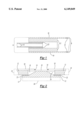
- FIG. 1 is a cross-sectional, schematic view of one embodiment of the bonded copper tube to titanium tube by means of the clad metal connecting member of the invention.
- FIG. 2 is a cross-sectional, schematic view through a metallurgically bonded joint between clad metal sheets utilizing a clad metal connecting member of the invention formed from a section of the clad metal sheets to be bonded.
- FIG. 1 there is shown in schematic, cross-sectional view, an embodiment of a metallurgically bonded joint between a copper tube 16 and a titanium tube 20.
- Metallurgical bonds are formed between the titanium tube 20 and the external titanium cladding of the titanium clad copper connecting member 8 comprised of copper layer 12 and titanium layer 10.
- the copper tube 16 is metallurgically bonded by soldering to the internal copper 12 portion of the clad connecting member at the junction between the copper tube 16 and the copper portion 12 of the clad connecting member at solder joint 22. Since titanium is a poor heat conductor in comparison with copper, it is desirable in order to speed up the soldering of copper tube 16 to copper layer 12 to remove an end portion, opposite to solder joint 22, not shown, of titanium layer 10, prior to soldering.
- FIG. 2 there is shown in schematic, cross-sectional view, a metallurgically bonded joint between sheets of a clad metal 24 comprised of titanium layer 10 and copper layer 12.
- a metallurgically bonded joint between sheets of a clad metal 24 comprised of titanium layer 10 and copper layer 12.
- a portion 18 of the underlying copper layer is removed and connecting member 26 is placed between the titanium clad copper sheets 24.
- Titanium welds 14 are made between the titanium clad layer of the titanium clad copper connecting member and the titanium portion 10 of the titanium clad sheets 24.
- the copper portions 12 of the titanium clad copper sheets 24 are soldered to the titanium clad connecting member 26 at the interface between connecting member 26 and the copper portions 12 of the titanium clad copper sheets 24.
- the welding of the titanium cladding of the connecting member to the titanium tubing requires the use of one of the well known inert gas welding methods. Since the weld is made at one end of the titanium clad copper connecting member, it is only necessary to remove a terminal portion of the underlying copper layer from the titanium clad copper connecting member prior to making the weld in order to avoid having the copper function as a heat sink and prevent the titanium from melting.
- the metallurgical bond can be made at the opposite end of the connecting member by soldering at relatively low temperatures. Accordingly, it is unnecessary to remove the titanium cladding from the portion of the titanium clad connecting member prior to soldering the copper tube to the copper portion of the connecting member.
- While a titanium clad copper connecting member has been used as an example of a means of connecting copper tubing to titanium tubing, one skilled in the art will understand that other corrosion resistant valve metals can be used as cladding layers instead of t other value SAL 2/15/00 metals SAL 2/15/00 can be used as cladding metals over corrosion susceptible metals.
- SAL 2/15/00 can be used as cladding metals over corrosion susceptible metals.
- other low-cost metals such as carbon steel can be used as underlying layers in forming the clad metal.
- a metallurgically bonded titanium clad, copper tube was machined so as to expose at one end of the tube a layer of titanium.
- the titanium layer was welded to a titanium tube of the same diameter in the presence of an inert gas.
- the other end of the titanium clad copper tube connecting member was soldered to a copper tube placed inside the opposite end of the titanium clad connecting member.
- the copper tubes on one side of the titanium clad connecting member are intended to pass to a compressor and an evaporator of a swimming pool heat pump unit.
- the titanium tubes are intended to pass to a heat exchanger unit in contact with chlorinated swimming pool water.
- a unit was assembled in this manner having 40 lineal feet of 3/4 inch titanium tubing and 20 lineal feet of 1/2 inch titanium SAL 2/15/00 tubing.
- the unit was tested in an evaluation laboratory and found to transfer 102,000 BTU per hour at a water temperature of 80° F., and an air temperature of 80° F., and 80% relative humidity.
- a similar unit was installed on a 24,000 gallon residential swimming pool and was found to transfer 105,000 BTU per hour with a water temperature of 84° F., an air temperature of 82° F., and a humidity of 82%.
- One embodiment of the invention described in this specification provides a more durable means of connecting the copper tubes of a swimming pool heat pump to a titanium heat exchanger which is in contact with swimming pool chlorinated water.
- titanium heat exchanger tubing has been connected to copper heat pump tubing utilizing a mechanical fitting in which a copper portion is joined to a titanium portion utilizing a threaded connector with an O-ring at a sealing junction.
- Such a mechanical connection has been required because a means of metallurgically joining a copper tube to a titanium tube was not available.
- copper tubing, cupronickel, 304 and 316 stainless steel, and other alloys were used in swimming pool heat exchangers.
Landscapes
- Engineering & Computer Science (AREA)
- Mechanical Engineering (AREA)
- Chemical & Material Sciences (AREA)
- Materials Engineering (AREA)
- Arc Welding In General (AREA)
- Pressure Welding/Diffusion-Bonding (AREA)
Abstract
Description
Claims (5)
Priority Applications (1)
| Application Number | Priority Date | Filing Date | Title |
|---|---|---|---|
| US09/507,367 US6149049A (en) | 1999-02-23 | 2000-02-18 | Metallurgical bonding of dissimilar metal tubes |
Applications Claiming Priority (2)
| Application Number | Priority Date | Filing Date | Title |
|---|---|---|---|
| US12124799P | 1999-02-23 | 1999-02-23 | |
| US09/507,367 US6149049A (en) | 1999-02-23 | 2000-02-18 | Metallurgical bonding of dissimilar metal tubes |
Publications (1)
| Publication Number | Publication Date |
|---|---|
| US6149049A true US6149049A (en) | 2000-11-21 |
Family
ID=22395464
Family Applications (1)
| Application Number | Title | Priority Date | Filing Date |
|---|---|---|---|
| US09/507,367 Expired - Lifetime US6149049A (en) | 1999-02-23 | 2000-02-18 | Metallurgical bonding of dissimilar metal tubes |
Country Status (2)
| Country | Link |
|---|---|
| US (1) | US6149049A (en) |
| WO (1) | WO2000050244A1 (en) |
Cited By (11)
| Publication number | Priority date | Publication date | Assignee | Title |
|---|---|---|---|---|
| US20050156014A1 (en) * | 2002-08-09 | 2005-07-21 | Korea Institute Of Science And Technology | Clad sheets for corrosion resistance and fabricating method thereof |
| US20060091187A1 (en) * | 2004-10-28 | 2006-05-04 | Samyoung Machinery Co., Ltd. | Flux and method for joining dissimilar metals |
| US20070155149A1 (en) * | 2005-12-29 | 2007-07-05 | Hailiang Zhao | Methods and structures for electrically coupling a conductor and a conductive element comprising a dissimilar material |
| CN100368189C (en) * | 2004-03-06 | 2008-02-13 | 韩国科学技术研究院 | Corrosion-resistant composite plate with high bonding strength and manufacturing method thereof |
| US20100143746A1 (en) * | 2008-12-10 | 2010-06-10 | Gm Global Technology Operations, Inc. | Methods of reducing corrosion between magnesium and another metal |
| US20130199763A1 (en) * | 2011-12-16 | 2013-08-08 | Furukawa-Skyaluminum Corp | Manufacturing Method Of Heat Exchanger, And Heat Exchanger Manufactured By Such Manufacturing Method |
| US8840350B2 (en) | 2011-10-20 | 2014-09-23 | Gm Global Technology Operations Llc. | Corrosion protection of magnesium components via fastener isolation |
| US20150311773A1 (en) * | 2014-04-28 | 2015-10-29 | GM Global Technology Operations LLC | Method of using a filler sheet having a flat surface to reduce core loss and weld failure in laminated stacked stators |
| US20160033181A1 (en) * | 2014-07-30 | 2016-02-04 | General Electric Company | Tube coupling and a method for forming a tube coupling |
| US9976819B2 (en) | 2007-10-05 | 2018-05-22 | Zodiac Pool Systems Llc | Header for heat exchanger |
| WO2023049717A1 (en) * | 2021-09-24 | 2023-03-30 | Apple Inc. | Clad parts |
Citations (7)
| Publication number | Priority date | Publication date | Assignee | Title |
|---|---|---|---|---|
| US3105293A (en) * | 1958-10-23 | 1963-10-01 | Union Carbide Corp | Brazing dissimilar metal members |
| US3443306A (en) * | 1966-08-03 | 1969-05-13 | Nooter Corp | Method of joining clad material |
| US3629932A (en) * | 1969-03-03 | 1971-12-28 | Dynamit Nobel Ag | Welding of explosive-plated metal sheets |
| US3733686A (en) * | 1971-10-27 | 1973-05-22 | Du Pont | Method for welding titanium clad steel |
| US3791026A (en) * | 1971-03-19 | 1974-02-12 | Commissariat Energie Atomique | Method of joining a niobium tube to a stainless steel tube |
| US4459062A (en) * | 1981-09-11 | 1984-07-10 | Monsanto Company | Clad metal joint closure |
| US4688691A (en) * | 1986-01-22 | 1987-08-25 | Nooter Corporation | Process for attaching clad components and pressure vessel formed thereby |
-
2000
- 2000-02-18 US US09/507,367 patent/US6149049A/en not_active Expired - Lifetime
- 2000-02-22 WO PCT/US2000/004571 patent/WO2000050244A1/en not_active Ceased
Patent Citations (7)
| Publication number | Priority date | Publication date | Assignee | Title |
|---|---|---|---|---|
| US3105293A (en) * | 1958-10-23 | 1963-10-01 | Union Carbide Corp | Brazing dissimilar metal members |
| US3443306A (en) * | 1966-08-03 | 1969-05-13 | Nooter Corp | Method of joining clad material |
| US3629932A (en) * | 1969-03-03 | 1971-12-28 | Dynamit Nobel Ag | Welding of explosive-plated metal sheets |
| US3791026A (en) * | 1971-03-19 | 1974-02-12 | Commissariat Energie Atomique | Method of joining a niobium tube to a stainless steel tube |
| US3733686A (en) * | 1971-10-27 | 1973-05-22 | Du Pont | Method for welding titanium clad steel |
| US4459062A (en) * | 1981-09-11 | 1984-07-10 | Monsanto Company | Clad metal joint closure |
| US4688691A (en) * | 1986-01-22 | 1987-08-25 | Nooter Corporation | Process for attaching clad components and pressure vessel formed thereby |
Cited By (16)
| Publication number | Priority date | Publication date | Assignee | Title |
|---|---|---|---|---|
| US20050156014A1 (en) * | 2002-08-09 | 2005-07-21 | Korea Institute Of Science And Technology | Clad sheets for corrosion resistance and fabricating method thereof |
| CN100368189C (en) * | 2004-03-06 | 2008-02-13 | 韩国科学技术研究院 | Corrosion-resistant composite plate with high bonding strength and manufacturing method thereof |
| US20060091187A1 (en) * | 2004-10-28 | 2006-05-04 | Samyoung Machinery Co., Ltd. | Flux and method for joining dissimilar metals |
| US7143928B2 (en) | 2004-10-28 | 2006-12-05 | Samyoung Machinery Co., Ltd. | Flux and method for joining dissimiliar metals |
| US20070155149A1 (en) * | 2005-12-29 | 2007-07-05 | Hailiang Zhao | Methods and structures for electrically coupling a conductor and a conductive element comprising a dissimilar material |
| US7539007B2 (en) | 2005-12-29 | 2009-05-26 | Medtronic, Inc. | Methods and structures for electrically coupling a conductor and a conductive element comprising a dissimilar material |
| US9976819B2 (en) | 2007-10-05 | 2018-05-22 | Zodiac Pool Systems Llc | Header for heat exchanger |
| US20100143746A1 (en) * | 2008-12-10 | 2010-06-10 | Gm Global Technology Operations, Inc. | Methods of reducing corrosion between magnesium and another metal |
| US8231936B2 (en) | 2008-12-10 | 2012-07-31 | GM Global Technology Operations LLC | Methods of reducing corrosion between magnesium and another metal |
| US8840350B2 (en) | 2011-10-20 | 2014-09-23 | Gm Global Technology Operations Llc. | Corrosion protection of magnesium components via fastener isolation |
| US20130199763A1 (en) * | 2011-12-16 | 2013-08-08 | Furukawa-Skyaluminum Corp | Manufacturing Method Of Heat Exchanger, And Heat Exchanger Manufactured By Such Manufacturing Method |
| US9789564B2 (en) * | 2011-12-16 | 2017-10-17 | Uacj Corporation | Manufacturing method of heat exchanger, and heat exchanger manufactured by such manufacturing method |
| US20150311773A1 (en) * | 2014-04-28 | 2015-10-29 | GM Global Technology Operations LLC | Method of using a filler sheet having a flat surface to reduce core loss and weld failure in laminated stacked stators |
| US20160033181A1 (en) * | 2014-07-30 | 2016-02-04 | General Electric Company | Tube coupling and a method for forming a tube coupling |
| US9950381B2 (en) * | 2014-07-30 | 2018-04-24 | Haier Us Appliance Solutions, Inc. | Tube coupling and a method for forming a tube coupling |
| WO2023049717A1 (en) * | 2021-09-24 | 2023-03-30 | Apple Inc. | Clad parts |
Also Published As
| Publication number | Publication date |
|---|---|
| WO2000050244A1 (en) | 2000-08-31 |
| WO2000050244A8 (en) | 2000-10-26 |
Similar Documents
| Publication | Publication Date | Title |
|---|---|---|
| US6149049A (en) | Metallurgical bonding of dissimilar metal tubes | |
| EP0150041B1 (en) | Corrosion resisting steel pipe and method of manufacturing same | |
| US4556240A (en) | Corrosion-resistant, double-wall pipe structures | |
| US4949895A (en) | Process of fixing internally titanium-lined doubled-walled tubing structure to titanium tube sheet | |
| WO2013084433A1 (en) | Heat exchanger for air conditioner | |
| US20180299211A1 (en) | Method for corrosion protection of tubing braze joints that connect copper and anodic alloy treated aluminum | |
| US3426420A (en) | Method of making brazed composite tubing for heat exchangers used in corrosive fluids | |
| US20090102588A1 (en) | Braze metal joint design | |
| KR101477636B1 (en) | Method for joining the tube and the tube sheet in shell and tube exchanger | |
| JPH0474099B2 (en) | ||
| KR100896560B1 (en) | Welding method of stainless steel pipe and connector | |
| JP2803989B2 (en) | Method of joining corrosion resistant metal lining material and lining tanks | |
| CN110587055B (en) | Heat exchanger manufacturing method and joint processing method and welding method with connecting pipe | |
| KR20040019111A (en) | Method and structure for connecting difficult-to-join pipes to be used at high temperature | |
| GB2055060A (en) | Heat exchanger and method of making | |
| JPS60177969A (en) | Method of jioning ti-al double tube and ti tube plate | |
| EP0788860B1 (en) | Heat exchange assembly and relative process and production plant | |
| JPS6335333B2 (en) | ||
| JPH11129090A (en) | Method of welding and coating thin metal sheet on thick metal substrate surface | |
| KR20160005403A (en) | Heat exchanger | |
| JPS5861987A (en) | Press welding method for double pipe by friction | |
| JPH0440637B2 (en) | ||
| JPH0471636B2 (en) | ||
| JPH10281355A (en) | Pipe joint and pipe connecting method by using the pipe joint | |
| JPS5934088A (en) | Corrosion-resisting double pipe joint structure |
Legal Events
| Date | Code | Title | Description |
|---|---|---|---|
| AS | Assignment |
Owner name: HURON TECH CORP., FLORIDA Free format text: ASSIGNMENT OF ASSIGNORS INTEREST;ASSIGNORS:LOFTFIELD, SCOTT A.;LOFTFIELD, RICHARD E.;REEL/FRAME:010993/0947 Effective date: 19990216 |
|
| STCF | Information on status: patent grant |
Free format text: PATENTED CASE |
|
| FEPP | Fee payment procedure |
Free format text: PAT HOLDER NO LONGER CLAIMS SMALL ENTITY STATUS, ENTITY STATUS SET TO UNDISCOUNTED (ORIGINAL EVENT CODE: STOL); ENTITY STATUS OF PATENT OWNER: LARGE ENTITY |
|
| AS | Assignment |
Owner name: FINNCHEM USA INC., SOUTH CAROLINA Free format text: CHANGE OF NAME;ASSIGNOR:HURON TECH CORP.;REEL/FRAME:014863/0519 Effective date: 20010609 |
|
| AS | Assignment |
Owner name: LAARS, INC., CALIFORNIA Free format text: ASSIGNMENT OF ASSIGNORS INTEREST;ASSIGNOR:FINNCHEM USA, INC.;REEL/FRAME:014567/0191 Effective date: 20040120 |
|
| FPAY | Fee payment |
Year of fee payment: 4 |
|
| AS | Assignment |
Owner name: JANDY POOL PRODUCTS, INC., CALIFORNIA Free format text: CHANGE OF NAME;ASSIGNOR:LAARS, INC.;REEL/FRAME:016700/0102 Effective date: 20050627 |
|
| FEPP | Fee payment procedure |
Free format text: PAYOR NUMBER ASSIGNED (ORIGINAL EVENT CODE: ASPN); ENTITY STATUS OF PATENT OWNER: LARGE ENTITY |
|
| FPAY | Fee payment |
Year of fee payment: 8 |
|
| AS | Assignment |
Owner name: ZODIAC POOL SYSTEMS, INC., CALIFORNIA Free format text: CHANGE OF NAME;ASSIGNOR:JANDY POOL PRODUCTS, INC.;REEL/FRAME:022408/0052 Effective date: 20080909 |
|
| FPAY | Fee payment |
Year of fee payment: 12 |
|
| AS | Assignment |
Owner name: ING BANK N.V., UNITED KINGDOM Free format text: INTELLECTUAL PROPERTY SECURITY AGREEMENT;ASSIGNOR:ZODIAC POOL SYSTEMS, INC.;REEL/FRAME:029732/0429 Effective date: 20130131 |
|
| AS | Assignment |
Owner name: ZODIAC POOL SYSTEMS, INC, CALIFORNIA Free format text: CORRECTIVE ASSIGNMENT TO CORRECT THE INCORRECT NUMBER INADVERTENTLY INCLUDED, 9312583 SHOULD BE 8312583 AND ADD A NUMBER INADVERTENTLY EXCLUDED 6149049. PREVIOUSLY RECORDED ON REEL 040935 FRAME 0141. ASSIGNOR(S) HEREBY CONFIRMS THE RELEASE OF SECURITY INTEREST;ASSIGNOR:ING BANK N.V., LONDON BRANCH;REEL/FRAME:046422/0882 Effective date: 20161220 |
|
| AS | Assignment |
Owner name: BANK OF AMERICA, N.A., CALIFORNIA Free format text: ABL INTELLECTUAL PROPERTY SECURITY AGREEMENT;ASSIGNORS:COVER-POOLS INCORPORATED;ZODIAC POOL SYSTEMS LLC;AQUA PRODUCTS, INC.;REEL/FRAME:046500/0291 Effective date: 20180702 Owner name: CREDIT SUISSE INTERNATIONAL, ENGLAND Free format text: SECURITY INTEREST;ASSIGNORS:COVER-POOLS INCORPORATED;ZODIAC POOL SYSTEMS LLC;AQUA PRODUCTS, INC.;REEL/FRAME:046622/0001 Effective date: 20180702 |
|
| AS | Assignment |
Owner name: ZODIAC POOL SYSTEMS LLC, DELAWARE Free format text: CHANGE OF NAME;ASSIGNOR:ZODIAC POOL SYSTEMS, INC.;REEL/FRAME:046634/0267 Effective date: 20170929 |
|
| AS | Assignment |
Owner name: HSBC BANK USA, N.A., NEW YORK Free format text: INTELLECTUAL PROPERTY SECURITY AGREEMENT ASSIGNMENT;ASSIGNOR:CREDIT SUISSE INTERNATIONAL;REEL/FRAME:058922/0901 Effective date: 20220127 |
|
| AS | Assignment |
Owner name: ZODIAC POOL SYSTEMS. INC., CALIFORNIA Free format text: RELEASE BY SECURED PARTY;ASSIGNOR:BANK OF AMERICA, N.A.;REEL/FRAME:058982/0912 Effective date: 20220127 Owner name: ZODIAC POOL SYSTEMS LLC, CALIFORNIA Free format text: RELEASE BY SECURED PARTY;ASSIGNOR:BANK OF AMERICA, N.A.;REEL/FRAME:058982/0912 Effective date: 20220127 Owner name: COVER-POOLS INCORPORATED, UTAH Free format text: RELEASE BY SECURED PARTY;ASSIGNOR:BANK OF AMERICA, N.A.;REEL/FRAME:058982/0912 Effective date: 20220127 Owner name: AQUA PRODUCTS, INC., NEW JERSEY Free format text: RELEASE BY SECURED PARTY;ASSIGNOR:BANK OF AMERICA, N.A.;REEL/FRAME:058982/0912 Effective date: 20220127 Owner name: AQUA PRODUCTS, INC., NEW JERSEY Free format text: RELEASE OF SECURITY INTEREST;ASSIGNOR:BANK OF AMERICA, N.A.;REEL/FRAME:058982/0912 Effective date: 20220127 Owner name: COVER-POOLS INCORPORATED, UTAH Free format text: RELEASE OF SECURITY INTEREST;ASSIGNOR:BANK OF AMERICA, N.A.;REEL/FRAME:058982/0912 Effective date: 20220127 Owner name: ZODIAC POOL SYSTEMS LLC, CALIFORNIA Free format text: RELEASE OF SECURITY INTEREST;ASSIGNOR:BANK OF AMERICA, N.A.;REEL/FRAME:058982/0912 Effective date: 20220127 Owner name: ZODIAC POOL SYSTEMS. INC., CALIFORNIA Free format text: RELEASE OF SECURITY INTEREST;ASSIGNOR:BANK OF AMERICA, N.A.;REEL/FRAME:058982/0912 Effective date: 20220127 |