US6148931A - Motor-driven hand tool - Google Patents
Motor-driven hand tool Download PDFInfo
- Publication number
- US6148931A US6148931A US08/797,603 US79760397A US6148931A US 6148931 A US6148931 A US 6148931A US 79760397 A US79760397 A US 79760397A US 6148931 A US6148931 A US 6148931A
- Authority
- US
- United States
- Prior art keywords
- motor
- opening
- removable grip
- hand tool
- grip
- Prior art date
- Legal status (The legal status is an assumption and is not a legal conclusion. Google has not performed a legal analysis and makes no representation as to the accuracy of the status listed.)
- Expired - Lifetime
Links
Images

Classifications
-
- B—PERFORMING OPERATIONS; TRANSPORTING
- B25—HAND TOOLS; PORTABLE POWER-DRIVEN TOOLS; MANIPULATORS
- B25F—COMBINATION OR MULTI-PURPOSE TOOLS NOT OTHERWISE PROVIDED FOR; DETAILS OR COMPONENTS OF PORTABLE POWER-DRIVEN TOOLS NOT PARTICULARLY RELATED TO THE OPERATIONS PERFORMED AND NOT OTHERWISE PROVIDED FOR
- B25F5/00—Details or components of portable power-driven tools not particularly related to the operations performed and not otherwise provided for
- B25F5/02—Construction of casings, bodies or handles
- B25F5/025—Construction of casings, bodies or handles with torque reaction bars for rotary tools
- B25F5/026—Construction of casings, bodies or handles with torque reaction bars for rotary tools in the form of an auxiliary handle
-
- B—PERFORMING OPERATIONS; TRANSPORTING
- B24—GRINDING; POLISHING
- B24B—MACHINES, DEVICES, OR PROCESSES FOR GRINDING OR POLISHING; DRESSING OR CONDITIONING OF ABRADING SURFACES; FEEDING OF GRINDING, POLISHING, OR LAPPING AGENTS
- B24B23/00—Portable grinding machines, e.g. hand-guided; Accessories therefor
- B24B23/005—Auxiliary devices used in connection with portable grinding machines, e.g. holders
Definitions
- the present invention relates to a motor-driven hand tool, such as an eccentric, angular or oscillating grinder or sander, with a removable grip.
- the motor-driven hand tool may involve either electric hand tools or compressor-driven hand tools. It also relates to the removable grip.
- Known hand tools are often equipped with two grips, one of them often embodied as a removable additional grip.
- power drills are known in which an elongated, straight grip with a protruding threaded portion can be screwed into an opening in the tool housing, transversely to the direction of the drill spindle. This is inconvenient because it requires rotating the grip several times around itself, which necessitates grasping it multiple times.
- the grip likewise extending transversely to the drill spindle, is mounted on the tool housing via a handcuff-like fastening that is fitted over the drill chuck region of the power drill, and a wing nut is tightened or loosened manually.
- This grip is extremely complicated to mount and unmount, since the power drill is either held between the user's upper arm and body or between his legs, while one hand puts the grip in the desired position relative to the tool housing and the other hand is needed to tighten the aforementioned wing nut.
- a grinding device of this general type whose removable additional grip can be moved in the circumferential direction, relative to the tool drive shaft, on the outside of the tool housing.
- the grip substantially comprises a spherical knob with a female thread, which can be screwed to a threaded bolt that protrudes out of a spherically curved receptacle that is movable in the circumferential direction. To be screwed on, the knob must be turned multiple times, which requires tedious repositioning of the hands.
- the grip cannot be shaped ergonomically; instead, its rotationally symmetrical design is predetermined.
- the grip When the grip is mounted or removed, the tool and the grip should be easy to manipulate; it should be unnecessary to change hand positions, nor should any problems arise in holding or supporting the hand tool.
- the grip has a securing element, disposed in the manipulation region of the grip and in particular rotatably movable, relative to the grip for the sake of manual mounting or release of the grip.
- the securing element is provided in the manipulation region of the grip and is movable, in particular rotatably, relative to it for mounting or releasing it, repeated changing of hand positions, as has been described as disadvantageous above, can be omitted; the grip is held or positioned with one hand, and the securing element for securing or releasing the grip is actuated with the same hand, in particular being rotated with the fingers, while the grip continues to be held by the palm of the hand or stays in the palm of the hand and is supported by it.
- the securing element is a screw, positionally secured in the grip, with a manually graspable and actuatable head.
- the head of the screw is advantageously grasped with the thumb and index finger or middle finger for the purpose and turned.
- other securing elements are conceivable, for instance in the form of a bayonet mount.
- this element need not necessarily be embodied by a screw; it might also be some threaded part that is connectable to an actuating head and can be screwed with a threaded bolt that protrudes from the tool housing.
- a limited-displacement pin with annular grooves that can interlock with the tool body, or an insertable pin that can be secured by rotation and engages a stop from behind or interlocks with it could be used.
- the grip has a recess, opening into its grip face, in which recess the securing element is manually actuatably provided.
- the securing element protrudes from the recess past the grip face and is thereby graspable, in particular rotatable.
- the recess need not be made so large that the hand tool user's fingers can get into the recess to reach the securing element; instead, the recess may be adapted substantially to the shape of the securing element and can surround it quite closely. From the visual standpoint as well, this makes for a compact, attractive appearance of the grip.
- the grip may for instance take the form of an ergonomically shaped pommel, and the recess may be extended in the form of an opening from one side of the grip face of the pommel to the other.
- the securing element preferably protrudes from two opposed sides past the grip face of the grip.
- the mounting position of the grip on the tool body is preferably predetermined. It proves to be advantageous if the grip is not unintentionally rotatable or pivotable relative to the tool body; this can preferably be attained by means of a complementary shaping of the tool body in the grip, for instance in that the radius of curvature of the side of the grip that can be placed against the tool body is embodied to correspond to the curvature of the tool body.
- ribs, lands, pins, and correspondingly embodied recesses in the other part may be provided.
- the grip includes two half-shell parts, which can be produced in a simple way, for instance by plastic injection molding, and can preferably be interlocked with one another.
- the half-shell parts define a through opening for the securing element, which element is inserted before the half-shell parts are closed and is positionally secured inside the opening by connecting the half-shell parts.
- the intrinsically manually actuatable securing element additionally has a tool engagement point, for instance for a screwdriver, socket wrench or the like.
- a tool engagement point for instance for a screwdriver, socket wrench or the like.
- FIG. 1 is a side view of a hand tool embodied according to the present invention
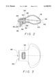
- FIG. 2 is a section through a removable grip of the hand tool of the FIG. 1;
- FIG. 3 is a plan view on the removable grip of the hand tool of FIG. 2.
- FIG. 1 shows a hand-guided eccentric grinder identified overall by reference numeral 2, with a first grip 4 solidly attached to the housing and defining a reach-through opening 6.
- An actuation key 8 extends into this opening 6 from the grip 4.
- the grip 4 is molded onto a motor housing 10, in which vent slits 12 are formed, but which can also be grasped with the hand in its upper region in order to manipulate and guide the eccentric grinder.
- an additional removable grip 14 is provided, in the vicinity of the eccentrically driven grinder head, in the lower region of the tool body.
- the grip 14 has an ergonomically curved pommel shape 16 and is T-shaped in plan view (FIG. 3), but without having any sharp corners or edges.
- the grip 14 includes two half-shell parts 18, 20 of a plastic material that can be interlocked with one another.
- the grip 14 can be secured to the tool body by means of a securing element 22, in the form of a screw 24, that is rotatable relative to the half-shell parts 18, 20.
- Both half-shell parts 18, 20 have an opening 30, 32 or through opening in their respective grip face 26, 28, as a result of which a recess 34 is defined or uncovered inside the grip 14 for receiving and positionally securing a head 38 of the screw 24.
- the half-shell parts 18, 20 also define a through opening 36 for the shaft of the screw 24 which intersects the recess 34.
- the screw 24 is placed in one of the half-shell parts and is positionally secured by joining or locking together the two half-shell parts; and as noted, the head 38 of the screw 24 is located in the recess 34.
- the screw head 38 protrudes past the grip face 26, 28 on both sides of the grip 14 and can thus easily be rotated with the thumb and index finger or middle finger, and the grip 14 can be held with the same hand without requiring tedious repositioning of the hands.
- the screw head 38 has a tool engagement point 40 for a socket wrench on its face end; this point can be reached through a conduit-like access opening 44, represented by the dashed line 42.
- the end of the grip 14 adjacent the opening end 36 may include ribs 46 which engages corresponding recesses (not shown) in the tool body. Engagement of the ribs in the corresponding recesses serve to better center the grip to the tool body.
Landscapes
- Engineering & Computer Science (AREA)
- Mechanical Engineering (AREA)
- Finish Polishing, Edge Sharpening, And Grinding By Specific Grinding Devices (AREA)
Abstract
Description
Claims (16)
Applications Claiming Priority (2)
| Application Number | Priority Date | Filing Date | Title |
|---|---|---|---|
| DE19606535A DE19606535C2 (en) | 1996-02-22 | 1996-02-22 | Motor-operated hand tool with removable handle |
| DE196065356 | 1996-02-22 |
Publications (1)
| Publication Number | Publication Date |
|---|---|
| US6148931A true US6148931A (en) | 2000-11-21 |
Family
ID=7786064
Family Applications (1)
| Application Number | Title | Priority Date | Filing Date |
|---|---|---|---|
| US08/797,603 Expired - Lifetime US6148931A (en) | 1996-02-22 | 1997-02-07 | Motor-driven hand tool |
Country Status (3)
| Country | Link |
|---|---|
| US (1) | US6148931A (en) |
| EP (1) | EP0791435B1 (en) |
| DE (2) | DE19606535C2 (en) |
Cited By (9)
| Publication number | Priority date | Publication date | Assignee | Title |
|---|---|---|---|---|
| USD465713S1 (en) | 2001-09-11 | 2002-11-19 | Chervon International Trading Co., Ltd. | Mini jig saw |
| US6602122B1 (en) * | 1998-12-31 | 2003-08-05 | C. & E. Fein Gmbh & Co. Kg | Electric power tool with rotatable handle |
| US6669543B2 (en) | 2001-10-31 | 2003-12-30 | Ingersoll-Rand Company | Interchangeable handle grip assembly, conversion kit, and tools incorporating same |
| USD490676S1 (en) | 2003-03-11 | 2004-06-01 | Black & Decker Inc. | Sander |
| USD498399S1 (en) | 2003-09-10 | 2004-11-16 | Chervon International Trading Co., Ltd. | Palm sander |
| USD503601S1 (en) * | 2003-09-15 | 2005-04-05 | Gmca Pty Limited | Multisander |
| US20050221738A1 (en) * | 2004-04-06 | 2005-10-06 | Cooper Vincent P | Orbital sander with vertical handle |
| US7222679B1 (en) * | 2006-03-17 | 2007-05-29 | Snap-On Incorporated | Random orbital sander |
| EP2468460A3 (en) * | 2010-12-22 | 2015-12-23 | HILTI Aktiengesellschaft | Additional handle, hand-held machine tool, system |
Families Citing this family (6)
| Publication number | Priority date | Publication date | Assignee | Title |
|---|---|---|---|---|
| JP3490914B2 (en) * | 1997-12-04 | 2004-01-26 | 株式会社シマノ | Fishing reel handle handle and handle assembly |
| DE29802027U1 (en) * | 1998-02-06 | 1998-03-26 | J. Wagner GmbH, 88677 Markdorf | Motorized hand tool |
| US6260591B1 (en) | 1999-08-11 | 2001-07-17 | Black & Decker Inc. | Biscuit joiner |
| DE29922108U1 (en) * | 1999-12-16 | 2000-02-17 | Hilti Ag, Schaan | Handheld grinder |
| DE102004016088B4 (en) * | 2004-04-01 | 2012-07-19 | Hilti Aktiengesellschaft | Additional handle assembly |
| DE102006023039B3 (en) * | 2006-05-17 | 2008-01-31 | Metabowerke Gmbh | Electric hand-held tool device e.g. eccentric sander, has carbon brush of motor and/or electronics accessed during removal of cover unit, and bearing carrier integrated into unit for partially supporting bearing of drive shaft of motor |
Citations (19)
| Publication number | Priority date | Publication date | Assignee | Title |
|---|---|---|---|---|
| US1809060A (en) * | 1929-08-15 | 1931-06-09 | Columbian Enameling & Stamping | Handle attachment for cooking utensils |
| US2499962A (en) * | 1945-07-21 | 1950-03-07 | Blackhawk Mfg Co | Portable impact tool assemblage |
| US2639564A (en) * | 1950-09-09 | 1953-05-26 | Clarke Sanding Machine Company | Oscillating sander |
| US2831463A (en) * | 1955-07-07 | 1958-04-22 | Atlas Copco Ab | Cushioning device for hammer tools |
| US3849943A (en) * | 1973-02-26 | 1974-11-26 | Rockwell International Corp | Power operated sanding machine |
| US4371043A (en) * | 1980-03-13 | 1983-02-01 | Masaharu Kubokawa | Vibration prevention handle for a vibration device |
| EP0249037A2 (en) * | 1986-06-10 | 1987-12-16 | Scintilla Ag | Auxiliary handle for a hand drill |
| DE3901728A1 (en) * | 1989-01-21 | 1990-07-26 | Licentia Gmbh | Screw-free connection of the handle shells of a double-shell housing for an electric tool |
| US5049012A (en) * | 1991-03-11 | 1991-09-17 | Ryobi Motor Products Corp. | Auxiliary handle for hand-held drill |
| US5074081A (en) * | 1991-06-12 | 1991-12-24 | Ryobi Motor Products Corp. | Sander with removable auxiliary handle |
| DE4132058A1 (en) * | 1991-09-26 | 1993-04-01 | Hilti Ag | Handle for hand-held power tool - incorporates clamping mechanism which fits around tool housing. |
| DE4203171C1 (en) * | 1992-02-05 | 1993-06-09 | Festo Kg, 7300 Esslingen, De | |
| DE9304887U1 (en) * | 1993-03-31 | 1993-08-05 | Karmann, Ahmet, 73033 Göppingen | Hand drill and screw machine |
| WO1993021751A1 (en) * | 1992-04-24 | 1993-11-11 | Poetker Dynamics Inc. | Attachable handle |
| FR2695054A1 (en) * | 1992-08-25 | 1994-03-04 | Dieu Andre | Universal tool holder with hand grip to which various tool can be fitted - includes base of fixation which can rotate about primary axis on handle and multipurpose tool guide rotatable about secondary axis which is at right angles to primary |
| DE3829801C2 (en) * | 1988-09-02 | 1995-01-26 | Metabowerke Kg | Additional handle for motor-operated hand machine tools |
| DE19508035A1 (en) * | 1994-04-08 | 1995-10-12 | Hitachi Koki Kk | Electric tool with main housing |
| US5466183A (en) * | 1991-01-31 | 1995-11-14 | Robert Bosch Gmbh | Hand held power tool with locking rotatable appendage |
| US5732869A (en) * | 1995-11-27 | 1998-03-31 | Hilti Aktiengesellschaft | Explosive powder charge operated setting tool |
-
1996
- 1996-02-22 DE DE19606535A patent/DE19606535C2/en not_active Expired - Fee Related
- 1996-12-04 DE DE59605400T patent/DE59605400D1/en not_active Expired - Fee Related
- 1996-12-04 EP EP96119429A patent/EP0791435B1/en not_active Expired - Lifetime
-
1997
- 1997-02-07 US US08/797,603 patent/US6148931A/en not_active Expired - Lifetime
Patent Citations (20)
| Publication number | Priority date | Publication date | Assignee | Title |
|---|---|---|---|---|
| US1809060A (en) * | 1929-08-15 | 1931-06-09 | Columbian Enameling & Stamping | Handle attachment for cooking utensils |
| US2499962A (en) * | 1945-07-21 | 1950-03-07 | Blackhawk Mfg Co | Portable impact tool assemblage |
| US2639564A (en) * | 1950-09-09 | 1953-05-26 | Clarke Sanding Machine Company | Oscillating sander |
| US2831463A (en) * | 1955-07-07 | 1958-04-22 | Atlas Copco Ab | Cushioning device for hammer tools |
| US3849943A (en) * | 1973-02-26 | 1974-11-26 | Rockwell International Corp | Power operated sanding machine |
| US4371043A (en) * | 1980-03-13 | 1983-02-01 | Masaharu Kubokawa | Vibration prevention handle for a vibration device |
| EP0249037A2 (en) * | 1986-06-10 | 1987-12-16 | Scintilla Ag | Auxiliary handle for a hand drill |
| DE3829801C2 (en) * | 1988-09-02 | 1995-01-26 | Metabowerke Kg | Additional handle for motor-operated hand machine tools |
| DE3901728A1 (en) * | 1989-01-21 | 1990-07-26 | Licentia Gmbh | Screw-free connection of the handle shells of a double-shell housing for an electric tool |
| US5466183A (en) * | 1991-01-31 | 1995-11-14 | Robert Bosch Gmbh | Hand held power tool with locking rotatable appendage |
| US5049012A (en) * | 1991-03-11 | 1991-09-17 | Ryobi Motor Products Corp. | Auxiliary handle for hand-held drill |
| US5074081A (en) * | 1991-06-12 | 1991-12-24 | Ryobi Motor Products Corp. | Sander with removable auxiliary handle |
| DE4132058A1 (en) * | 1991-09-26 | 1993-04-01 | Hilti Ag | Handle for hand-held power tool - incorporates clamping mechanism which fits around tool housing. |
| DE4203171C1 (en) * | 1992-02-05 | 1993-06-09 | Festo Kg, 7300 Esslingen, De | |
| WO1993021751A1 (en) * | 1992-04-24 | 1993-11-11 | Poetker Dynamics Inc. | Attachable handle |
| FR2695054A1 (en) * | 1992-08-25 | 1994-03-04 | Dieu Andre | Universal tool holder with hand grip to which various tool can be fitted - includes base of fixation which can rotate about primary axis on handle and multipurpose tool guide rotatable about secondary axis which is at right angles to primary |
| DE9304887U1 (en) * | 1993-03-31 | 1993-08-05 | Karmann, Ahmet, 73033 Göppingen | Hand drill and screw machine |
| DE19508035A1 (en) * | 1994-04-08 | 1995-10-12 | Hitachi Koki Kk | Electric tool with main housing |
| US5558570A (en) * | 1994-04-08 | 1996-09-24 | Hitachi Koki Co., Ltd. | Power tool having detachable auxiliary handle |
| US5732869A (en) * | 1995-11-27 | 1998-03-31 | Hilti Aktiengesellschaft | Explosive powder charge operated setting tool |
Cited By (9)
| Publication number | Priority date | Publication date | Assignee | Title |
|---|---|---|---|---|
| US6602122B1 (en) * | 1998-12-31 | 2003-08-05 | C. & E. Fein Gmbh & Co. Kg | Electric power tool with rotatable handle |
| USD465713S1 (en) | 2001-09-11 | 2002-11-19 | Chervon International Trading Co., Ltd. | Mini jig saw |
| US6669543B2 (en) | 2001-10-31 | 2003-12-30 | Ingersoll-Rand Company | Interchangeable handle grip assembly, conversion kit, and tools incorporating same |
| USD490676S1 (en) | 2003-03-11 | 2004-06-01 | Black & Decker Inc. | Sander |
| USD498399S1 (en) | 2003-09-10 | 2004-11-16 | Chervon International Trading Co., Ltd. | Palm sander |
| USD503601S1 (en) * | 2003-09-15 | 2005-04-05 | Gmca Pty Limited | Multisander |
| US20050221738A1 (en) * | 2004-04-06 | 2005-10-06 | Cooper Vincent P | Orbital sander with vertical handle |
| US7222679B1 (en) * | 2006-03-17 | 2007-05-29 | Snap-On Incorporated | Random orbital sander |
| EP2468460A3 (en) * | 2010-12-22 | 2015-12-23 | HILTI Aktiengesellschaft | Additional handle, hand-held machine tool, system |
Also Published As
| Publication number | Publication date |
|---|---|
| DE59605400D1 (en) | 2000-07-13 |
| EP0791435A1 (en) | 1997-08-27 |
| EP0791435B1 (en) | 2000-06-07 |
| DE19606535A1 (en) | 1997-08-28 |
| DE19606535C2 (en) | 1999-01-07 |
Similar Documents
| Publication | Publication Date | Title |
|---|---|---|
| US6148931A (en) | Motor-driven hand tool | |
| JP3032009B2 (en) | Hand-held machine tool | |
| US20050200087A1 (en) | Rotary tool with quick connect means and attachments thereto | |
| US6120362A (en) | Ergonomic grinder | |
| AU757769B2 (en) | Angle attachment for power tool | |
| US7392568B2 (en) | Hand-held power tool with an auxiliary handle | |
| EP1693162B1 (en) | Hand-held power tool | |
| US5902080A (en) | Spiral cutting tool with detachable battery pack | |
| US6155916A (en) | Power-driven hand tool | |
| CA2415860C (en) | Automatic locking depth guide for cutting tools and the like | |
| US5813805A (en) | Spiral cutting tool with detachable handle | |
| USRE38729E1 (en) | Combination of an electric-powered tool and an illuminating device received in the tool | |
| EP1437203B1 (en) | Attachment for power tool | |
| US20080078067A1 (en) | Handle | |
| EP0936032A2 (en) | Power tool | |
| US7014232B2 (en) | Removable auxiliary handle for tools | |
| JPH06504490A (en) | handheld machine tool | |
| US7677281B2 (en) | Power router tool | |
| US6935438B2 (en) | Battery operated electrical tool | |
| US7418892B2 (en) | Detachable wrench handle assembly | |
| JPH06504487A (en) | handheld machine tool | |
| JPH0426988B2 (en) | ||
| US20220072677A1 (en) | Hand-guided battery-operated electric power tool | |
| US9604833B1 (en) | Power assist for manual can opener | |
| WO2006008140A1 (en) | Handgrip for a hand tool |
Legal Events
| Date | Code | Title | Description |
|---|---|---|---|
| AS | Assignment |
Owner name: METABOWERKE GMBH & CO., GERMANY Free format text: ASSIGNMENT OF ASSIGNORS INTEREST;ASSIGNORS:NYBER, OLIVER;PENKA, WALTER;REEL/FRAME:008457/0796 Effective date: 19970114 |
|
| STCF | Information on status: patent grant |
Free format text: PATENTED CASE |
|
| FEPP | Fee payment procedure |
Free format text: PAYOR NUMBER ASSIGNED (ORIGINAL EVENT CODE: ASPN); ENTITY STATUS OF PATENT OWNER: LARGE ENTITY |
|
| FPAY | Fee payment |
Year of fee payment: 4 |
|
| FPAY | Fee payment |
Year of fee payment: 8 |
|
| FEPP | Fee payment procedure |
Free format text: PAYER NUMBER DE-ASSIGNED (ORIGINAL EVENT CODE: RMPN); ENTITY STATUS OF PATENT OWNER: LARGE ENTITY Free format text: PAYOR NUMBER ASSIGNED (ORIGINAL EVENT CODE: ASPN); ENTITY STATUS OF PATENT OWNER: LARGE ENTITY |
|
| FPAY | Fee payment |
Year of fee payment: 12 |