US6148850A - Washing machine outlet box with common tailpiece for two drain outlets - Google Patents
Washing machine outlet box with common tailpiece for two drain outlets Download PDFInfo
- Publication number
- US6148850A US6148850A US09/295,658 US29565899A US6148850A US 6148850 A US6148850 A US 6148850A US 29565899 A US29565899 A US 29565899A US 6148850 A US6148850 A US 6148850A
- Authority
- US
- United States
- Prior art keywords
- washing machine
- bottom wall
- drain
- outlet box
- tailpiece
- Prior art date
- Legal status (The legal status is an assumption and is not a legal conclusion. Google has not performed a legal analysis and makes no representation as to the accuracy of the status listed.)
- Expired - Lifetime
Links
Images
Classifications
-
- F—MECHANICAL ENGINEERING; LIGHTING; HEATING; WEAPONS; BLASTING
- F16—ENGINEERING ELEMENTS AND UNITS; GENERAL MEASURES FOR PRODUCING AND MAINTAINING EFFECTIVE FUNCTIONING OF MACHINES OR INSTALLATIONS; THERMAL INSULATION IN GENERAL
- F16L—PIPES; JOINTS OR FITTINGS FOR PIPES; SUPPORTS FOR PIPES, CABLES OR PROTECTIVE TUBING; MEANS FOR THERMAL INSULATION IN GENERAL
- F16L5/00—Devices for use where pipes, cables or protective tubing pass through walls or partitions
- F16L5/02—Sealing
- F16L5/14—Sealing for double-walled or multi-channel pipes
-
- D—TEXTILES; PAPER
- D06—TREATMENT OF TEXTILES OR THE LIKE; LAUNDERING; FLEXIBLE MATERIALS NOT OTHERWISE PROVIDED FOR
- D06F—LAUNDERING, DRYING, IRONING, PRESSING OR FOLDING TEXTILE ARTICLES
- D06F39/00—Details of washing machines not specific to a single type of machines covered by groups D06F9/00 - D06F27/00
- D06F39/08—Liquid supply or discharge arrangements
-
- D—TEXTILES; PAPER
- D06—TREATMENT OF TEXTILES OR THE LIKE; LAUNDERING; FLEXIBLE MATERIALS NOT OTHERWISE PROVIDED FOR
- D06F—LAUNDERING, DRYING, IRONING, PRESSING OR FOLDING TEXTILE ARTICLES
- D06F33/00—Control of operations performed in washing machines or washer-dryers
- D06F33/30—Control of washing machines characterised by the purpose or target of the control
- D06F33/32—Control of operational steps, e.g. optimisation or improvement of operational steps depending on the condition of the laundry
- D06F33/42—Control of operational steps, e.g. optimisation or improvement of operational steps depending on the condition of the laundry of draining
-
- Y—GENERAL TAGGING OF NEW TECHNOLOGICAL DEVELOPMENTS; GENERAL TAGGING OF CROSS-SECTIONAL TECHNOLOGIES SPANNING OVER SEVERAL SECTIONS OF THE IPC; TECHNICAL SUBJECTS COVERED BY FORMER USPC CROSS-REFERENCE ART COLLECTIONS [XRACs] AND DIGESTS
- Y10—TECHNICAL SUBJECTS COVERED BY FORMER USPC
- Y10T—TECHNICAL SUBJECTS COVERED BY FORMER US CLASSIFICATION
- Y10T137/00—Fluid handling
- Y10T137/6851—With casing, support, protector or static constructional installations
- Y10T137/6966—Static constructional installations
- Y10T137/6969—Buildings
- Y10T137/698—Wall
Definitions
- the present invention relates to a washing machine outlet box that includes a common tailpiece for two drain ports in the bottom of the box, one for the washing machine drain hose and the other for a condensate line from a water softener or air conditioner or the like.
- Washing machine outlet boxes are frequently used in new construction or remodeling to provide the plumbing connections necessary for a washing machine, including water supply lines (hot and cold) and a drain port for the washing machine drain hose.
- the drain port usually includes a tailpiece extending downwardly from the bottom of the box for attaching a drain pipe connected to the sanitary drainage system of the building.
- the drain pipe may be solvent welded to the tailpiece where both are made of a suitable plastic.
- washing machine outlet boxes may also be designed to provide a drain for a condensate line from a water softener or an air conditioner. In this manner, the drainage for both the washing machine and the condensate line may be routed through the same box.
- local construction codes typically do not permit the condensate line to drain directly into the same drain port in the box as the washing machine hose.
- a washing machine outlet box 30 would normally include two separate drain ports (one for the washing machine hose and one for the condensate line) and two separate tailpieces. During installation of the washing machine outlet box, a plumber is required to connect these two separate tailpieces to the drain pipe.
- the upper end of a straight piece of pipe is solvent welded to the tailpiece of the washing machine hose drain port and the upper end of another straight piece of pipe is solvent welded to the tailpiece of the condensate line drain port;
- the lower end of one straight piece is solvent welded to the upper end of a T piece of pipe and the lower end of the other straight piece is solvent welded to the upper end of an elbow piece of pipe;
- the side end of the T piece and the lower end of the elbow piece are solvent welded to opposite ends of another short straight piece;
- the bottom end of the T piece is solvent welded to the drain pipe.
- local construction codes typically require an air gap between the condensate line and the drain, necessitating that the bottom end of the condensate line be positioned above its drain port. This may require the plumber to mount a clamp either to the rear wall of the box or to a construction surface above the box to secure the condensate line in place relative to the washing machine outlet box.
- the present invention provides a washing machine outlet box that accommodates a condensate line as well as a washing machine drain line while minimizing the number of steps required to install the box.
- the present invention provides a washing machine outlet box comprising a housing including a bottom wall, first and second juxtaposed drain ports in the bottom wall for a washing machine drain hose and a condensate line, and a common tailpiece for both drain ports extending from the bottom wall.
- the common tailpiece includes an outlet for connection to a drain pipe and wall sections that define a first fluid passageway from the first drain port to the outlet and a second fluid passageway from the second drain port to the outlet.
- Providing a common tailpiece greatly reduces the number of joints necessary to connect the washing machine hose drain port and the condensate line drain port to the drain pipe. For example, in the preferred washing machine outlet box, only one joint is needed between the tailpiece outlet and drain pipe to connect both drain ports to the drain pipe.
- the bottom wall of the box housing preferably includes an elongated opening that surrounds both drain ports. If pressure testing is to be performed, a test cap is used to cover the elongated opening. Such a test cap includes a base portion and two knockout portions that, after pressure testing, are removed from the base portion to form the drain ports.
- the elongated opening in the bottom wall is preferably surrounded by a non-symmetrically shaped recess and the base portion of the test cap has the same non-symmetrical shape to insure that the test cap is properly positioned relative to the opening. It may be noted, however, that if a test cap is not used, the oblong opening in the bottom wall (in conjunction with the tailpiece) may itself define the drain ports.
- the knockout portions are each sized so that the drain ports formed thereby may accommodate the washing machine drain hose. In this manner, the hose may be placed in either opening depending on the particular plumbing arrangement of the condensate line.
- the knockout portions preferably each include a screwdriver stop and a pull handle projecting upwardly from its top surface for convenient removal.
- the common tailpiece preferably includes external wall sections defining a chamber between an opening in the bottom wall of the housing and a dividing wall section dividing the chamber into the two passageways.
- the top edge of the dividing wall section and the bottom surface of the test cap preferably include complementary stepped contours to insure proper positioning relative to each other.
- the bottom edge of the dividing wall section preferably includes a pipe stop to properly position the drain pipe within the common tailpiece.
- the present invention additionally or alternatively includes a clamp assembly for securing the condensate line in alignment with one of the drain ports.
- the clamp assembly includes a base secured to the drain port for the condensate line, a clamp for clamping the condensate line, and a support structure cantilevering upwardly from the base for supporting the clamp at the elevated level.
- the clamp is circumferentially adjustable to accommodate different diameters of condensate lines.
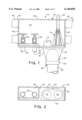
- FIG. 1 is a front elevation view of a washing machine outlet box and a clamping assembly according to the present invention, the box being shown with its test cap in place and its plumbing installed;
- FIG. 2 is a top plan view of the bottom wall of the box of FIG. 1 prior to the condensate clamp and the plumbing being installed;
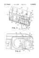
- FIG. 3 is an enlarged top front perspective view of the washing machine outlet box of FIG. 1 prior to the condensate clamp and the plumbing being installed;
- FIG. 4 is an enlarged bottom front perspective view of a portion of the washing machine outlet box of FIG. 3, including particularly the common tailpiece;
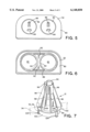
- FIG. 5 is a further enlarged top front perspective view of the test cap for the box
- FIG. 6 is a bottom front perspective view of the test cap of FIG. 5.
- FIG. 7 is a further enlarged perspective top front view of the clamping assembly used to clamp the condensate line to one of the box drain ports.
- the washing machine outlet box 10 accommodates the plumbing for a washing machine, namely water supply lines 14c and 14h, shut-off valves 16c and 16h, and a washing machine drain hose 18.
- the box 10 accommodates a condensate line 20 from a water softener or an air conditioner or the like.
- a common tailpiece 22 provides separate passageways 24 and 26 for the drain of the washing machine drain hose 18 and the condensate line 20, respectively, into a drain pipe 28 connected to the sanitary drainage system of the building.
- the washing machine outlet box 10 is desirably molded out of a suitable plastic and includes a housing 32 having bottom and top walls 34 and 36, a rear wall 38 and side walls 40. Attached to the outer surface of each side wall 40 are loops 42 for receipt of mounting brackets 44 used to mount the washing machine outlet box 10 to studs or other structural members of a building before the wall board or other sheet material is installed to finish the wall. Once the wall material is installed, the box 10 provides a finished look for the plumbing connections to a washing machine or the like.
- the bottom wall 34 of the housing 32 includes a rectangular pedestal 46 with two circular openings 48 for the water supply lines 14 to which the shut-off valves 16 are connected.
- An oblong opening 50 is also formed in the bottom wall 34.
- a test cap 52 (shown with its knockout portions removed) covers the oblong opening 50 and defines two juxtaposed drain ports 54 and 56, one for the washing machine drain hose 18 and the other for the condensate line 20.
- the tailpiece 22 is desirably integrally molded to the bottom wall 34 of the housing 32 and surrounds the oblong opening 50 whereby the separate passageways 24 and 26 extend from the drain ports 54 and 56, respectively, to the drain pipe 28.
- This has the advantage that only one solvent welded joint 58 is needed to connect both the washing machine hose drain port 54 and the condensate line drain port 56 to the drain pipe 28.
- the outlet of the tailpiece 22 is solvent welded to the upper end of the drain pipe 28.
- the washing machine outlet box 10 is shown prior to installation of the test cap 52.
- the oblong or elongated opening 50 is surrounded by a recess 60 in the top surface 62 of the bottom wall 34.
- the recess 60 has a non-symmetrical shape relative to the front and rear edges of the bottom wall 34 which, in the illustrated embodiment, is a rectangle having rounded rear corners.
- the test cap 52 defines the drain ports 54 and 56.
- the test cap 52 may be omitted and the oblong opening 50, in combination with the tailpiece 22, may instead define the drain ports 54 and 56.
- both of the drain ports 54 and 56 are sized to accommodate the washing machine drain hose 18 (e.g., each may have a two inch diameter) so that the hose 18 may be inserted into either opening depending on the plumbing arrangement.
- the tailpiece 22 is preferably integrally formed with the bottom wall 34 of the housing 32 and more preferably is formed in one piece with the bottom wall 34.
- a separate tailpiece that is, for example, solvent welded to the bottom wall 34, is possible with and contemplated by the present invention.
- the tailpiece 22 includes a bottom circular flange 64 and funnel shaped wall sections 66 that extend downwardly from the wall 68 surrounding the oblong opening 50 to the flange 64.
- the flange 64 is the outlet of the tailpiece 22 connected to the drain pipe 28 and thus is sized (e.g., has a two inch diameter) to be directly solvent welded to a standard drain pipe.
- Within the upper end of the tailpiece 22 is a chamber 70 containing a dividing wall section or partition 72 that defines the passageways 24 and 26 from the drain ports 54 and 56 to the tailpiece outlet 74.
- the top edge of the dividing wall section 72 has a stepped contour which, in the illustrated embodiment, is formed by a central trapezoidal-shaped step 76 (FIG. 3).
- the bottom edge of the dividing wall section 72 includes a pair of downward projecting tabs 78 which function as a "pipe stop" to properly position the top of the drain pipe 28 within the tailpiece 22 during installation (FIG. 4).
- test cap 52 is shown in detail.
- the test cap 52 is used to temporarily seal the drain opening 50 in the bottom wall 34 of the washing machine outlet box 10 so that pressure testing of the sanitary drainage system may be performed.
- the test cap 52 includes a base portion 80 which is solvent welded to the bottom wall 34 and two frangible knockout portions 82 which, when removed, form the drain ports 54 and 56.
- the knockout portions 82 each include a screwdriver stop 84 and a pull handle 86 projecting upwardly from the top surface of the knockouts (FIG. 5).
- the stops 84 are located forward of the pull handles 86 so that the tip of a screwdriver may readily be placed against the stops through the open front of the box 10 and the handle of the screwdriver tapped by a hammer to break one or both knockout portions 82 out of the test cap.
- the base portion 80 has the same shape as the recess 60 formed on the bottom wall 34 and the non-symmetry of this shape insures that the screwdriver stops 84 are located forward of the pull handles 86.
- the bottom surface of the base portion 80 includes downwardly extending webs 88, 90 and 92.
- the web 88 is of the same oblong shape/size as the drain opening 50 and has a complementary contour.
- the webs 90 each have a semi-circular shape and join with a respective curved section of the oblong web 88 to form a pair of circular rims around the knockout portions 82.
- the webs 92 extend centrally inward from the straight sections of the oblong web 88 and are sized/shaped to fit around the trapezoidal step 76 of the tailpiece's dividing wall section 72.
- the condensate drain clamp assembly 12 is shown separately from the washing machine outlet box 10.
- the clamp assembly 12 includes a base 94, clamp sections 96, and support legs 98.
- the base 94 is preferably designed to be secured to either of the drain ports 54 and 56 in the bottom wall 34 of the washing machine outlet box 10.
- the clamp sections 96 are preferably shaped so that together they form a cylindrical clamp for the condensate line 20 (FIG. 1). Pairs of support legs 98 individually support each of the clamp sections 96 at an elevated level relative to the bottom wall 34 and are preferably flexible so that they may be flexed outwardly to expand the size/diameter of the cylindrical clamp for accommodating condensate lines of different diameters. In this manner, the condensate line 20 is held in alignment with one or the other of the drain ports 54 and 56 while at the same time providing the required air gap beneath the bottom end of the condensate line 20 and associated drain port.
- the base 94 of the clamp assembly 12 is designed to be snap-fitted into the selected drain port 54/56.
- the base 94 includes a cylindrical rim 100 and a circular flange 102 extending outwardly from the top edge thereof.
- a series of circumferentially spaced snap tabs 104 are formed on the rim 100 and corresponding slots 106 are located on the flange 102 for accessing the snap tabs 104. (In the illustrated embodiment, three snap tabs 104 and three slots 106 are shown, these being located between every other pair of support legs 98.)
- the snap tabs 104 are pressed inward to allow the rim 100 to be inserted into the selected drain port 54/56.
- rim 100 Upon release of the snap tabs 104, rim 100 will be secured in place within the selected drain port by the flange 102 and snap tabs 104 overlying opposite ends of the selected drain port 54/56 as schematically shown in phantom lines in FIG. 7.
- the clamp assembly 12 is secured to the right-hand drain port 56.
- the clamp assembly could instead be secured to the left-hand drain port 54 for a different plumbing arrangement.
- the clamp assembly 12 could be secured to a drain opening in any washing machine outlet box that accommodates a condensate line.
- the base 94 of the clamp 12 could be solvent welded to the bottom wall of a washing machine outlet box.
- the top wall 36 of the washing machine outlet box 10 may include openings 108, 110, 112 and 114.
- One of the openings 114 may be cut in a starburst pattern forming a series of triangular flaps or fingers 116 to hold the condensate line 20 in alignment with the associated drain port 56. In this manner, condensate lines of different diameters may be accommodated and held in alignment with the associated drain port 56.
- the opening 112 aligned with the other drain port 54 may also have this starburst design so that the condensate line 20 may alternatively pass through this opening.
- the openings 108 and 110 contain knockouts 118 and 120 that would be removed for passage of the water supply lines 24 if the water lines were located above the box 10.
Landscapes
- Engineering & Computer Science (AREA)
- General Engineering & Computer Science (AREA)
- Mechanical Engineering (AREA)
- Textile Engineering (AREA)
- Detail Structures Of Washing Machines And Dryers (AREA)
- Quick-Acting Or Multi-Walled Pipe Joints (AREA)
Abstract
Description
Claims (26)
Priority Applications (3)
| Application Number | Priority Date | Filing Date | Title |
|---|---|---|---|
| US09/295,658 US6148850A (en) | 1999-04-21 | 1999-04-21 | Washing machine outlet box with common tailpiece for two drain outlets |
| CA002291976A CA2291976C (en) | 1999-04-21 | 1999-12-09 | Washing machine outlet box with common tailpiece for two drain outlets |
| CA002592623A CA2592623C (en) | 1999-04-21 | 1999-12-09 | Washing machine outlet box with common tailpiece for two drain outlets |
Applications Claiming Priority (1)
| Application Number | Priority Date | Filing Date | Title |
|---|---|---|---|
| US09/295,658 US6148850A (en) | 1999-04-21 | 1999-04-21 | Washing machine outlet box with common tailpiece for two drain outlets |
Publications (1)
| Publication Number | Publication Date |
|---|---|
| US6148850A true US6148850A (en) | 2000-11-21 |
Family
ID=23138675
Family Applications (1)
| Application Number | Title | Priority Date | Filing Date |
|---|---|---|---|
| US09/295,658 Expired - Lifetime US6148850A (en) | 1999-04-21 | 1999-04-21 | Washing machine outlet box with common tailpiece for two drain outlets |
Country Status (2)
| Country | Link |
|---|---|
| US (1) | US6148850A (en) |
| CA (1) | CA2291976C (en) |
Cited By (23)
| Publication number | Priority date | Publication date | Assignee | Title |
|---|---|---|---|---|
| US6561548B1 (en) * | 1999-09-10 | 2003-05-13 | Hansgrohe | Protective device for sanitary fittings |
| US6732758B2 (en) | 2001-03-23 | 2004-05-11 | Oatey Co. | Fluid shock absorber assembly |
| US6845785B1 (en) | 2003-09-30 | 2005-01-25 | Lsp Products Group, Inc. | Flush-mount supply line and drain connector |
| US20050067017A1 (en) * | 2003-09-30 | 2005-03-31 | Condon Duane R. | Flush-mount supply line and drain connector |
| US20050166965A1 (en) * | 2004-01-30 | 2005-08-04 | Minnick Michael W. | Universal washing machine outlet box |
| US6938640B2 (en) | 2002-12-02 | 2005-09-06 | Michael S. Mustoe | Recessed box assembly for a dryer exhaust hose |
| US7360553B1 (en) | 2005-08-02 | 2008-04-22 | Sioux Chief Mfg. Co., Inc. | Modular utility box system |
| US20100000614A1 (en) * | 2008-07-02 | 2010-01-07 | Zahuranec Terry L | Plumbing supply boxes |
| US8020581B1 (en) | 2007-02-27 | 2011-09-20 | Sioux Chief Mfg. Co., Inc. | Secondary drainage funnel for a laundry box |
| WO2012125212A1 (en) * | 2011-03-16 | 2012-09-20 | Chilcoat Edward A | Crescent shaped hose or hose adapter |
| AU2012101742B4 (en) * | 2012-11-26 | 2013-07-18 | M.A.G. Industries (Australla) Pty Ltd | Improvements in or relating to tundish devices |
| US20150026946A1 (en) * | 2011-04-18 | 2015-01-29 | Mordehay Yakir Ben Jacov | Modular Plumbing Panel and Method of Installation |
| US9388555B2 (en) | 2014-01-14 | 2016-07-12 | Ips Corporation | Plumbing outlet box with integrated mounting features |
| US9394674B2 (en) | 2014-01-14 | 2016-07-19 | Ips Corporation | Plumbing outlet box with integrated mounting features |
| US9518381B2 (en) | 2014-01-14 | 2016-12-13 | Ips Corporation | Plumbing outlet box with mounting features |
| CN108018682A (en) * | 2016-11-04 | 2018-05-11 | 青岛海尔洗衣机有限公司 | A kind of screw cover and the washing machine using the screw cover |
| US10385554B2 (en) | 2016-09-30 | 2019-08-20 | Accor Technology, Inc. | Outlet box |
| US10724214B2 (en) * | 2018-12-17 | 2020-07-28 | Jones Stephens Corp. | Thermal expansion protection assembly |
| US10781549B2 (en) | 2019-01-31 | 2020-09-22 | Whirlpool Corporation | Dual drain system with Y-hose |
| US10865550B1 (en) * | 2018-02-12 | 2020-12-15 | Lsp Products Group, Inc. | Outlet box with integrated funnel |
| WO2022036401A1 (en) * | 2020-08-18 | 2022-02-24 | KRAMAH Pty Ltd | In-wall tundish assembly |
| US11306427B2 (en) * | 2019-07-10 | 2022-04-19 | Accor Technologies, Inc. | Drain box and funnel |
| US12077950B2 (en) | 2021-07-08 | 2024-09-03 | Reliance Worldwide Corporation | Appliance outlet box |
Citations (15)
| Publication number | Priority date | Publication date | Assignee | Title |
|---|---|---|---|---|
| US3096782A (en) * | 1960-10-27 | 1963-07-09 | Juanita W Caruth | Water tap receptacle and drain |
| US3148698A (en) * | 1962-03-01 | 1964-09-15 | Raymond L Arnold | Prefabricated water supply and drain unit for washing machines |
| US3495276A (en) * | 1967-03-08 | 1970-02-17 | Charles Robert Suess | Wall receptacle for water conduits of washing machines |
| US3620246A (en) * | 1970-01-09 | 1971-11-16 | Behring Corp | Plumbing apparatus |
| US3718154A (en) * | 1971-01-07 | 1973-02-27 | Conrad Ind Inc | Washing machine outlet box |
| US3750697A (en) * | 1971-05-13 | 1973-08-07 | E Kump | Structural building frame incorporating utilities |
| US3847175A (en) * | 1973-02-16 | 1974-11-12 | Carrcraft Mfg Co | Universal installation box for use in dryer vent systems and in water supply and drain systems |
| US3862433A (en) * | 1973-06-18 | 1975-01-21 | Leroy H Rousselet | Washing machine outlet device |
| US3996959A (en) * | 1973-05-21 | 1976-12-14 | Caruth Juanita W | Washer-connector service box |
| US4073018A (en) * | 1975-03-31 | 1978-02-14 | Mckenney's, Inc. | Internal back vent system |
| US4410004A (en) * | 1980-04-04 | 1983-10-18 | Oatey Co. | Laundry outlet box |
| US4564249A (en) * | 1984-01-06 | 1986-01-14 | Logsdon Duane D | Miniature washing machine box |
| US4716925A (en) * | 1987-06-23 | 1988-01-05 | Industrial Polychemical Service, Inc. | Reversible washing machine box |
| US4865072A (en) * | 1988-12-28 | 1989-09-12 | Duane Logsdon | Washing machine connection boxes |
| US4934410A (en) * | 1990-02-12 | 1990-06-19 | Industrial Polychemical Service, Inc. | Dual outlet washing machine box |
-
1999
- 1999-04-21 US US09/295,658 patent/US6148850A/en not_active Expired - Lifetime
- 1999-12-09 CA CA002291976A patent/CA2291976C/en not_active Expired - Lifetime
Patent Citations (15)
| Publication number | Priority date | Publication date | Assignee | Title |
|---|---|---|---|---|
| US3096782A (en) * | 1960-10-27 | 1963-07-09 | Juanita W Caruth | Water tap receptacle and drain |
| US3148698A (en) * | 1962-03-01 | 1964-09-15 | Raymond L Arnold | Prefabricated water supply and drain unit for washing machines |
| US3495276A (en) * | 1967-03-08 | 1970-02-17 | Charles Robert Suess | Wall receptacle for water conduits of washing machines |
| US3620246A (en) * | 1970-01-09 | 1971-11-16 | Behring Corp | Plumbing apparatus |
| US3718154A (en) * | 1971-01-07 | 1973-02-27 | Conrad Ind Inc | Washing machine outlet box |
| US3750697A (en) * | 1971-05-13 | 1973-08-07 | E Kump | Structural building frame incorporating utilities |
| US3847175A (en) * | 1973-02-16 | 1974-11-12 | Carrcraft Mfg Co | Universal installation box for use in dryer vent systems and in water supply and drain systems |
| US3996959A (en) * | 1973-05-21 | 1976-12-14 | Caruth Juanita W | Washer-connector service box |
| US3862433A (en) * | 1973-06-18 | 1975-01-21 | Leroy H Rousselet | Washing machine outlet device |
| US4073018A (en) * | 1975-03-31 | 1978-02-14 | Mckenney's, Inc. | Internal back vent system |
| US4410004A (en) * | 1980-04-04 | 1983-10-18 | Oatey Co. | Laundry outlet box |
| US4564249A (en) * | 1984-01-06 | 1986-01-14 | Logsdon Duane D | Miniature washing machine box |
| US4716925A (en) * | 1987-06-23 | 1988-01-05 | Industrial Polychemical Service, Inc. | Reversible washing machine box |
| US4865072A (en) * | 1988-12-28 | 1989-09-12 | Duane Logsdon | Washing machine connection boxes |
| US4934410A (en) * | 1990-02-12 | 1990-06-19 | Industrial Polychemical Service, Inc. | Dual outlet washing machine box |
Cited By (32)
| Publication number | Priority date | Publication date | Assignee | Title |
|---|---|---|---|---|
| US6561548B1 (en) * | 1999-09-10 | 2003-05-13 | Hansgrohe | Protective device for sanitary fittings |
| US6732758B2 (en) | 2001-03-23 | 2004-05-11 | Oatey Co. | Fluid shock absorber assembly |
| US6938640B2 (en) | 2002-12-02 | 2005-09-06 | Michael S. Mustoe | Recessed box assembly for a dryer exhaust hose |
| US6845785B1 (en) | 2003-09-30 | 2005-01-25 | Lsp Products Group, Inc. | Flush-mount supply line and drain connector |
| US20050067017A1 (en) * | 2003-09-30 | 2005-03-31 | Condon Duane R. | Flush-mount supply line and drain connector |
| US7614419B2 (en) | 2004-01-30 | 2009-11-10 | Oatey Co. | Universal washing machine outlet box |
| US20050166965A1 (en) * | 2004-01-30 | 2005-08-04 | Minnick Michael W. | Universal washing machine outlet box |
| US7270144B2 (en) | 2004-01-30 | 2007-09-18 | Oatey Co. | Universal washing machine outlet box |
| US20070215211A1 (en) * | 2004-01-30 | 2007-09-20 | Minnick Michael W | Universal washing machine outlet box |
| US7360553B1 (en) | 2005-08-02 | 2008-04-22 | Sioux Chief Mfg. Co., Inc. | Modular utility box system |
| US8020581B1 (en) | 2007-02-27 | 2011-09-20 | Sioux Chief Mfg. Co., Inc. | Secondary drainage funnel for a laundry box |
| US20100000614A1 (en) * | 2008-07-02 | 2010-01-07 | Zahuranec Terry L | Plumbing supply boxes |
| US10060102B2 (en) | 2008-07-02 | 2018-08-28 | Oatey Co. | Plumbing supply boxes |
| WO2012125212A1 (en) * | 2011-03-16 | 2012-09-20 | Chilcoat Edward A | Crescent shaped hose or hose adapter |
| US20150026946A1 (en) * | 2011-04-18 | 2015-01-29 | Mordehay Yakir Ben Jacov | Modular Plumbing Panel and Method of Installation |
| US9834914B2 (en) * | 2011-04-18 | 2017-12-05 | Mordehay Yakir Ben Jacov | Modular plumbing panel and method of installation |
| AU2012101742B4 (en) * | 2012-11-26 | 2013-07-18 | M.A.G. Industries (Australla) Pty Ltd | Improvements in or relating to tundish devices |
| US9394674B2 (en) | 2014-01-14 | 2016-07-19 | Ips Corporation | Plumbing outlet box with integrated mounting features |
| US9650765B2 (en) | 2014-01-14 | 2017-05-16 | Ips Corporation | Plumbing outlet box with integrated mounting features |
| US9518381B2 (en) | 2014-01-14 | 2016-12-13 | Ips Corporation | Plumbing outlet box with mounting features |
| US9650766B2 (en) | 2014-01-14 | 2017-05-16 | Ips Corporation | Plumbing outlet box with integrated mounting features |
| US9388555B2 (en) | 2014-01-14 | 2016-07-12 | Ips Corporation | Plumbing outlet box with integrated mounting features |
| US11066815B2 (en) | 2016-09-30 | 2021-07-20 | Accor Technology, Inc. | Outlet box |
| US10385554B2 (en) | 2016-09-30 | 2019-08-20 | Accor Technology, Inc. | Outlet box |
| CN108018682A (en) * | 2016-11-04 | 2018-05-11 | 青岛海尔洗衣机有限公司 | A kind of screw cover and the washing machine using the screw cover |
| US10865550B1 (en) * | 2018-02-12 | 2020-12-15 | Lsp Products Group, Inc. | Outlet box with integrated funnel |
| US10724214B2 (en) * | 2018-12-17 | 2020-07-28 | Jones Stephens Corp. | Thermal expansion protection assembly |
| US10781549B2 (en) | 2019-01-31 | 2020-09-22 | Whirlpool Corporation | Dual drain system with Y-hose |
| US11814768B2 (en) | 2019-01-31 | 2023-11-14 | Whirlpool Corporation | Dual drain system with Y-hose |
| US11306427B2 (en) * | 2019-07-10 | 2022-04-19 | Accor Technologies, Inc. | Drain box and funnel |
| WO2022036401A1 (en) * | 2020-08-18 | 2022-02-24 | KRAMAH Pty Ltd | In-wall tundish assembly |
| US12077950B2 (en) | 2021-07-08 | 2024-09-03 | Reliance Worldwide Corporation | Appliance outlet box |
Also Published As
| Publication number | Publication date |
|---|---|
| CA2291976C (en) | 2007-11-20 |
| CA2291976A1 (en) | 2000-10-21 |
Similar Documents
| Publication | Publication Date | Title |
|---|---|---|
| US6148850A (en) | Washing machine outlet box with common tailpiece for two drain outlets | |
| US4410004A (en) | Laundry outlet box | |
| US6125881A (en) | Dual drain outlet box | |
| US4716925A (en) | Reversible washing machine box | |
| US3847175A (en) | Universal installation box for use in dryer vent systems and in water supply and drain systems | |
| US7360553B1 (en) | Modular utility box system | |
| US7614419B2 (en) | Universal washing machine outlet box | |
| US4158471A (en) | Washing machine outlet box | |
| US6155286A (en) | Washing machine outlet box | |
| US3996959A (en) | Washer-connector service box | |
| US5121594A (en) | Method for attaching a poke-through electrical fitting | |
| US7735511B1 (en) | Modular laundry box assembly | |
| US6845785B1 (en) | Flush-mount supply line and drain connector | |
| US8020581B1 (en) | Secondary drainage funnel for a laundry box | |
| US20050067017A1 (en) | Flush-mount supply line and drain connector | |
| US7285722B2 (en) | Mounting bracket | |
| US4138747A (en) | Drainage fittings and/or wash-house fittings | |
| US5713385A (en) | Air gap body for reverse osmosis system | |
| CA2592623C (en) | Washing machine outlet box with common tailpiece for two drain outlets | |
| US7854337B1 (en) | Breakaway closure member with offset nipple | |
| JPH10121554A (en) | Wall-drain type toilet bowl and fitting structure thereof | |
| JP3570097B2 (en) | Mounting structure of the faucet joint elbow | |
| JPH10331221A (en) | Housing drain piping device | |
| JP3470239B2 (en) | Toilet bowl with flush water distributor | |
| JP2645512B2 (en) | Flexible tube terminal holder |
Legal Events
| Date | Code | Title | Description |
|---|---|---|---|
| AS | Assignment |
Owner name: OATEY CO., OHIO Free format text: ASSIGNMENT OF ASSIGNORS INTEREST;ASSIGNORS:RAUN A. KOPP;MICHAEL W. MINNICK;ROBERT S. KANE;REEL/FRAME:009917/0697 Effective date: 19990419 |
|
| STCF | Information on status: patent grant |
Free format text: PATENTED CASE |
|
| FPAY | Fee payment |
Year of fee payment: 4 |
|
| AS | Assignment |
Owner name: KEYBANK NATIONAL ASSOCIATION, AS AGENT, OHIO Free format text: SECURITY AGREEMENT;ASSIGNOR:OATEY CO.;REEL/FRAME:018972/0226 Effective date: 20061214 |
|
| FPAY | Fee payment |
Year of fee payment: 8 |
|
| AS | Assignment |
Owner name: KEYBANK NATIONAL ASSOCIATION, AS COLLATERAL AGENT, Free format text: AMENDED AND RESTATED INTELLECTUAL PROPERTY SECURITY AGREEMENT;ASSIGNOR:OATEY CO.;REEL/FRAME:027046/0145 Effective date: 20110923 |
|
| FEPP | Fee payment procedure |
Free format text: PAYOR NUMBER ASSIGNED (ORIGINAL EVENT CODE: ASPN); ENTITY STATUS OF PATENT OWNER: LARGE ENTITY |
|
| FPAY | Fee payment |
Year of fee payment: 12 |
|
| AS | Assignment |
Owner name: OATEY CO., OHIO Free format text: RELEASE BY SECURED PARTY;ASSIGNOR:KEYBANK NATIONAL ASSOCIATION, AS COLLATERAL AGENT;REEL/FRAME:032380/0793 Effective date: 20140228 |