US6148696A - Ratchet screw driver - Google Patents
Ratchet screw driver Download PDFInfo
- Publication number
- US6148696A US6148696A US09/323,383 US32338399A US6148696A US 6148696 A US6148696 A US 6148696A US 32338399 A US32338399 A US 32338399A US 6148696 A US6148696 A US 6148696A
- Authority
- US
- United States
- Prior art keywords
- barrel
- gear
- pawls
- handle
- engaged
- Prior art date
- Legal status (The legal status is an assumption and is not a legal conclusion. Google has not performed a legal analysis and makes no representation as to the accuracy of the status listed.)
- Expired - Fee Related
Links
Images


Classifications
-
- B—PERFORMING OPERATIONS; TRANSPORTING
- B25—HAND TOOLS; PORTABLE POWER-DRIVEN TOOLS; MANIPULATORS
- B25B—TOOLS OR BENCH DEVICES NOT OTHERWISE PROVIDED FOR, FOR FASTENING, CONNECTING, DISENGAGING OR HOLDING
- B25B23/00—Details of, or accessories for, spanners, wrenches, screwdrivers
- B25B23/0007—Connections or joints between tool parts
- B25B23/0042—Connection means between screwdriver handle and screwdriver shaft
-
- B—PERFORMING OPERATIONS; TRANSPORTING
- B25—HAND TOOLS; PORTABLE POWER-DRIVEN TOOLS; MANIPULATORS
- B25B—TOOLS OR BENCH DEVICES NOT OTHERWISE PROVIDED FOR, FOR FASTENING, CONNECTING, DISENGAGING OR HOLDING
- B25B13/00—Spanners; Wrenches
- B25B13/46—Spanners; Wrenches of the ratchet type, for providing a free return stroke of the handle
- B25B13/461—Spanners; Wrenches of the ratchet type, for providing a free return stroke of the handle with concentric driving and driven member
- B25B13/462—Spanners; Wrenches of the ratchet type, for providing a free return stroke of the handle with concentric driving and driven member the ratchet parts engaging in a direction radial to the tool operating axis
- B25B13/463—Spanners; Wrenches of the ratchet type, for providing a free return stroke of the handle with concentric driving and driven member the ratchet parts engaging in a direction radial to the tool operating axis a pawl engaging an externally toothed wheel
-
- B—PERFORMING OPERATIONS; TRANSPORTING
- B25—HAND TOOLS; PORTABLE POWER-DRIVEN TOOLS; MANIPULATORS
- B25B—TOOLS OR BENCH DEVICES NOT OTHERWISE PROVIDED FOR, FOR FASTENING, CONNECTING, DISENGAGING OR HOLDING
- B25B15/00—Screwdrivers
- B25B15/02—Screwdrivers operated by rotating the handle
- B25B15/04—Screwdrivers operated by rotating the handle with ratchet action
Definitions
- the present invention relates to a screw driver, and more particularly to a ratchet screw driver.
- a typical ratchet screw driver is disclosed in U.S. Pat. No. 5,687,820 to Lin and includes a driving stem that is secured to the handle and may not be easily disengaged from the handle for being replaced with the other driving stems of different configurations or sizes.
- the present invention has arisen to mitigate and/or obviate the afore-described disadvantages of the conventional screw drivers
- the primary objective of the present invention is to provide a ratchet screw driver including a structure for allowing the driving stems to be changeably engaged with the screw driver handle.
- a ratchet screw driver comprising a handle including a bore formed therein and including a first end having an engaging opening formed therein and communicating with the bore of the handle, a barrel including a stud extended therefrom and engaged into the engaging opening of the handle and moved in concert with the handle, the barrel including an orifice formed therein and communicating wit h the bore of the handle when the stud of the barrel is engaged into the engaging opening of the handle, the barrel including a pair of opposite passages formed therein and communicating with the orifice of the barrel, a gear rotatably received in the orifice of the barrel and including an aperture formed therein, a pair of pawls slidably received in the passages of the barrel for engaging with the gear, at least one driving stem selectively engaged into the bore of the handle through the aperture of the gear and the orifice of the barrel, means for biasing the pawls to engage with the gear, and means for selectively disengaging the pawls from the gear
- the aperture of the gear includes a non-circular cross section for receiving the driving stem having a corresponding non-circular cross section, the gear includes at least one notch communicating with the aperture of the gear, the driving stem has at least one flange for engaging into the notch of the gear.
- the biasing means includes a biasing member having two ends engaged into the passages of the barrel and engaged with the pawls for biasing the pawls to engage with the gear.
- the barrel includes an outer peripheral portion having an annular groove for receiving the biasing member.
- a fastener is further provided for securing the middle portion of the biasing member to the barrel.
- the ends of the biasing member each includes a bead for engaging with the pawls.
- the barrel includes a curved slot communicating with the orifice.
- An actuator is engaged into the curved slot of the barrel and located between the pawls for moving the pawls against the biasing means.
- a control ferrule is rotatable engaged onto the barrel, the actuator is extended from the control ferrule and moved against the pawls by the control ferrule.
- a positioning device is further provided for positioning the control ferrule to the barrel.
- the barrel includes three cavities, the control ferrule includes a spring-biased projection engaged with either of the cavities of the barrel for positioning the control ferrule to the barrel.
- a flexible extension may further be extendibly and slidably received in the driving stem for extending the driving length of the ratchet screw driver.
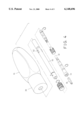
- FIG. 1 is an exploded view of a screw driver in accordance with the present invention
- FIG. 2 is an exploded view of the screw driver and a driving stem that may be selectively and changeably engaged into the screw driver;
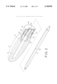
- FIG. 3 is a perspective view of the screw driver, in which one half of the screw driver is cut off for showing the inner structure of the screw driver;
- FIG. 4 is an exploded view illustrating the application of the screw driver.
- FIG. 5 is a cross sectional view of the screw driver as shown in FIG. 4.
- a ratchet screw driver in accordance with the present invention comprises a handle 10 including a bore 11 formed therein and including an engaging opening 12 formed in one end thereof and communicating with the bore 11 and having a non-circular cross section, particularly the hexagonal cross section.
- a ratchet tool cartridge 30 includes a barrel 50 having a stud 58 extended from one end thereof and engaged into the engaging opening 17 of the handle 10.
- the stud 58 includes a non-circular cross section, particularly the hexagonal cross section, for engaging with the corresponding cross section of the engaging opening 12 of the handle 10, by such as a force-fitted engagement, and for allowing the stud 58 and the barrel 50 to be secured to the handle 10 and rotated in concert with the handle 10.
- the stud 58 may also be secured to the handle 10 with a key device.
- the barrel 50 includes an orifice 54 formed therein and facing away from the stud 58 for rotatably receiving a gear, particularly a ratchet gear 34 therein.
- the gear 34 includes a number of teeth 341 formed on the outer peripheral portion thereof and includes an aperture 342 formed therein for receiving a driving stem 40 (FIG. 2) or 42 (FIG. 3) or 60 (FIGS. 4, 5).
- the aperture 342 of the gear 34 includes a non-circular cross section, particularly the hexagonal cross section, for engaging with the corresponding non-circular or hexagonal cross section 41 of the driving stem 40, and for allowing the driving stem 40 to be secured to the gear 34 and rotated in concert with the gear 34.
- the inner portion 59 (FIGS.
- the orifice 54 of the barrel 50 includes a circular cross section having a size smaller than that of the orifice 54 of the barrel 50 for forming a shoulder therein and for stably retaining the gear 34 in place.
- the driving stems 40, 42, 60 may be engaged into the bore 11 of the handle 10 via the inner portion 59 of the orifice 54 of the barrel 50.
- the gear 34 may further includes one or more notches 343 formed therein for receiving the flanges 421 or 62 of the driving stems 42 (FIG. 3) or 60 (FIGS. 4, 5), for allowing the driving stems 42, 60 of a circular cross section to be secured to the gear 34 and to be rotated in concert with the gear 34.
- Various kinds of driving stems 40, 42, 60 may thus be replaceably or changeably engaged into the gear 34.
- the barrel 50 includes a passage or a pair of opposite passages 52, 53 formed therein and communicating with the orifice 54 of the barrel 50 for slidably receiving a pair of pawls 32, 33 each of Which includes one or more teeth 321, 331 for engaging with the teeth 341 of the gear 34 and for controlling the driving directions of the gear 34 and thus the driving stems 40, 42, 60 by the barrel 50 and the handle 10.
- a pair of pawls 32, 33 each of Which includes one or more teeth 321, 331 for engaging with the teeth 341 of the gear 34 and for controlling the driving directions of the gear 34 and thus the driving stems 40, 42, 60 by the barrel 50 and the handle 10.
- the barrel 50 includes an annular groove 51 formed in the outer peripheral portion thereof for receiving a C-shaped resilient or biasing member 35.
- the biasing member 35 includes a hole 351 formed in the middle portion thereof for receiving a fastener 31, such as a screw or a rivet or the like, which is engaged into the barrel 50 for securing the middle portion of the biasing member 35 to the barrel 50.
- the biasing member 35 includes two ends each having a bead 352, 353 formed thereon and engaged into the passages 52, 53 of the barrel 50 and engaged with the pawls 32, 33 for biasing the pawls 32, 33 to engage with the gear 34.
- the provision of the bead 352, 353 to engage with the pawls 32, 33 is to prevent the pawls 32, 30 from being damaged by the ends of the biasing member 35.
- the barrel 50 further includes a curved slot 55 (FIG. 1) formed therein and formed beside the orifice 54 thereof and communicating with the orifice 54 and the passages 52, 53 thereof.
- a cover or a control ferrule 20 is rotatably engaged onto the barrel 50 and preferably covers the biasing member 35 (FIGS. 2, 3, 5) for shielding and preventing the biasing member 35 from being damaged or from hurting the users.
- the control ferrule 20 includes an actuator 21 extended inward therefrom and extended inward of the slot 55 of the barrel 50 and located between the pawls 32, 33 for actuating or for moving the pawls 32, 33 against the biasing member 35.
- the control ferrule 20 includes a spring-biased projection 23 provided therein for engaging with either of three cavities 57 of the barrel 50 and for positioning the control ferrule 20 to the barrel 50 at three relative positions where the actuator 91 moves either of the pawls 32, 33 against the biasing member 35 or where the actuator 21 is located between the pawls 32, 33 and do not act onto the pawls 32, 33.
- a flexible extension 61 may further be provided and slidably engaged in the driving stem 60 and may include an engaging opening 63 formed in one end thereof for receiving the tool bits 64, for example.
- the flexible extension 61 and the corresponding configuration thereof has been disclosed in the applicant's prior U.S. Pat. No. 5,732,606 to Chiang which is also taken as a reference for the present invention.
- the ratchet screw driver in accordance with the present invention includes a structure for allowing various kinds of driving stems to be changeably engaged with the screw driver handle.
Abstract
A ratchet screw driver includes a barrel having a stud en gaged into a handle and having a pair of opposite passages for slidably receiving a pair of pawls. A gear is rotatably received in the barrel and has an aperture for receiving various kinds of driving stems. A spring is engaged on the barrel and has two end beads engaged with the pawls for biasing the pawls to engage with the gear. The barrel includes a curved slot for receiving an actuator which is engaged into the curved slot of the barrel and located between the pawls for moving the pawls against the spring.
Description
1. Field of the Invention
The present invention relates to a screw driver, and more particularly to a ratchet screw driver.
2. Description of the Prior Art
A typical ratchet screw driver is disclosed in U.S. Pat. No. 5,687,820 to Lin and includes a driving stem that is secured to the handle and may not be easily disengaged from the handle for being replaced with the other driving stems of different configurations or sizes.
The applicant has developed an extendible screw driver which is disclosed in U.S. Pat. No. 5,732,606 to Chiang and which includes a flexible extension that may be extended outward of the handle for increasing the length of the driving stem. However, no ratchet mechanism is applied to the screw driver and the driving stem also may not be disengaged from the handle for being replaced with the other driving stems.
The present invention has arisen to mitigate and/or obviate the afore-described disadvantages of the conventional screw drivers
The primary objective of the present invention is to provide a ratchet screw driver including a structure for allowing the driving stems to be changeably engaged with the screw driver handle.
In accordance with one aspect of the invention, there is provided a ratchet screw driver comprising a handle including a bore formed therein and including a first end having an engaging opening formed therein and communicating with the bore of the handle, a barrel including a stud extended therefrom and engaged into the engaging opening of the handle and moved in concert with the handle, the barrel including an orifice formed therein and communicating wit h the bore of the handle when the stud of the barrel is engaged into the engaging opening of the handle, the barrel including a pair of opposite passages formed therein and communicating with the orifice of the barrel, a gear rotatably received in the orifice of the barrel and including an aperture formed therein, a pair of pawls slidably received in the passages of the barrel for engaging with the gear, at least one driving stem selectively engaged into the bore of the handle through the aperture of the gear and the orifice of the barrel, means for biasing the pawls to engage with the gear, and means for selectively disengaging the pawls from the gear. Various kinds of driving stems may be selectively engaged into the gear and the barrel.
The aperture of the gear includes a non-circular cross section for receiving the driving stem having a corresponding non-circular cross section, the gear includes at least one notch communicating with the aperture of the gear, the driving stem has at least one flange for engaging into the notch of the gear.
The biasing means includes a biasing member having two ends engaged into the passages of the barrel and engaged with the pawls for biasing the pawls to engage with the gear. The barrel includes an outer peripheral portion having an annular groove for receiving the biasing member. A fastener is further provided for securing the middle portion of the biasing member to the barrel. The ends of the biasing member each includes a bead for engaging with the pawls.
The barrel includes a curved slot communicating with the orifice. An actuator is engaged into the curved slot of the barrel and located between the pawls for moving the pawls against the biasing means.
A control ferrule is rotatable engaged onto the barrel, the actuator is extended from the control ferrule and moved against the pawls by the control ferrule. A positioning device is further provided for positioning the control ferrule to the barrel. The barrel includes three cavities, the control ferrule includes a spring-biased projection engaged with either of the cavities of the barrel for positioning the control ferrule to the barrel.
A flexible extension may further be extendibly and slidably received in the driving stem for extending the driving length of the ratchet screw driver.
Further objectives and advantages of the present invention will become apparent from a careful reading of a detailed description provided hereinbelow, with appropriate reference to accompanying drawings.
FIG. 1 is an exploded view of a screw driver in accordance with the present invention;
FIG. 2 is an exploded view of the screw driver and a driving stem that may be selectively and changeably engaged into the screw driver;
FIG. 3 is a perspective view of the screw driver, in which one half of the screw driver is cut off for showing the inner structure of the screw driver;
FIG. 4 is an exploded view illustrating the application of the screw driver; and
FIG. 5 is a cross sectional view of the screw driver as shown in FIG. 4.
Referring to the drawings, and initially to FIGS. 1 and 2, a ratchet screw driver in accordance with the present invention comprises a handle 10 including a bore 11 formed therein and including an engaging opening 12 formed in one end thereof and communicating with the bore 11 and having a non-circular cross section, particularly the hexagonal cross section. A ratchet tool cartridge 30 includes a barrel 50 having a stud 58 extended from one end thereof and engaged into the engaging opening 17 of the handle 10. The stud 58 includes a non-circular cross section, particularly the hexagonal cross section, for engaging with the corresponding cross section of the engaging opening 12 of the handle 10, by such as a force-fitted engagement, and for allowing the stud 58 and the barrel 50 to be secured to the handle 10 and rotated in concert with the handle 10. The stud 58 may also be secured to the handle 10 with a key device.
The barrel 50 includes an orifice 54 formed therein and facing away from the stud 58 for rotatably receiving a gear, particularly a ratchet gear 34 therein. The gear 34 includes a number of teeth 341 formed on the outer peripheral portion thereof and includes an aperture 342 formed therein for receiving a driving stem 40 (FIG. 2) or 42 (FIG. 3) or 60 (FIGS. 4, 5). The aperture 342 of the gear 34 includes a non-circular cross section, particularly the hexagonal cross section, for engaging with the corresponding non-circular or hexagonal cross section 41 of the driving stem 40, and for allowing the driving stem 40 to be secured to the gear 34 and rotated in concert with the gear 34. The inner portion 59 (FIGS. 2, 3) of the orifice 54 of the barrel 50 includes a circular cross section having a size smaller than that of the orifice 54 of the barrel 50 for forming a shoulder therein and for stably retaining the gear 34 in place. The driving stems 40, 42, 60 may be engaged into the bore 11 of the handle 10 via the inner portion 59 of the orifice 54 of the barrel 50. The gear 34 may further includes one or more notches 343 formed therein for receiving the flanges 421 or 62 of the driving stems 42 (FIG. 3) or 60 (FIGS. 4, 5), for allowing the driving stems 42, 60 of a circular cross section to be secured to the gear 34 and to be rotated in concert with the gear 34. Various kinds of driving stems 40, 42, 60 may thus be replaceably or changeably engaged into the gear 34.
The barrel 50 includes a passage or a pair of opposite passages 52, 53 formed therein and communicating with the orifice 54 of the barrel 50 for slidably receiving a pair of pawls 32, 33 each of Which includes one or more teeth 321, 331 for engaging with the teeth 341 of the gear 34 and for controlling the driving directions of the gear 34 and thus the driving stems 40, 42, 60 by the barrel 50 and the handle 10. One example of the engagement of the pawls 32, 33 with the gear 34 has been disclosed in U.S. Pat. No. 5,687,820 to Lin which is thus taken as a reference for the present invention. The barrel 50 includes an annular groove 51 formed in the outer peripheral portion thereof for receiving a C-shaped resilient or biasing member 35. The biasing member 35 includes a hole 351 formed in the middle portion thereof for receiving a fastener 31, such as a screw or a rivet or the like, which is engaged into the barrel 50 for securing the middle portion of the biasing member 35 to the barrel 50. The biasing member 35 includes two ends each having a bead 352, 353 formed thereon and engaged into the passages 52, 53 of the barrel 50 and engaged with the pawls 32, 33 for biasing the pawls 32, 33 to engage with the gear 34. The provision of the bead 352, 353 to engage with the pawls 32, 33 is to prevent the pawls 32, 30 from being damaged by the ends of the biasing member 35.
The barrel 50 further includes a curved slot 55 (FIG. 1) formed therein and formed beside the orifice 54 thereof and communicating with the orifice 54 and the passages 52, 53 thereof. A cover or a control ferrule 20 is rotatably engaged onto the barrel 50 and preferably covers the biasing member 35 (FIGS. 2, 3, 5) for shielding and preventing the biasing member 35 from being damaged or from hurting the users. The control ferrule 20 includes an actuator 21 extended inward therefrom and extended inward of the slot 55 of the barrel 50 and located between the pawls 32, 33 for actuating or for moving the pawls 32, 33 against the biasing member 35. The control ferrule 20 includes a spring-biased projection 23 provided therein for engaging with either of three cavities 57 of the barrel 50 and for positioning the control ferrule 20 to the barrel 50 at three relative positions where the actuator 91 moves either of the pawls 32, 33 against the biasing member 35 or where the actuator 21 is located between the pawls 32, 33 and do not act onto the pawls 32, 33.
Referring next to FIGS. 4 and 5, a flexible extension 61 may further be provided and slidably engaged in the driving stem 60 and may include an engaging opening 63 formed in one end thereof for receiving the tool bits 64, for example. The flexible extension 61 and the corresponding configuration thereof has been disclosed in the applicant's prior U.S. Pat. No. 5,732,606 to Chiang which is also taken as a reference for the present invention.
Accordingly, the ratchet screw driver in accordance with the present invention includes a structure for allowing various kinds of driving stems to be changeably engaged with the screw driver handle.
Although this invention has been described with a certain degree of particularity, it is to be understood that the present disclosure has been made by way of example only and that numerous changes in the detailed construction and the combination and arrangement of parts may be resorted to without departing from the spirit and scope of the invention as hereinafter claimed.
Claims (10)
1. A ratchet screw driver comprising:
a handle including a bore formed therein and including a first end having an engaging opening formed therein and communicating with said bore of said handle,
a barrel including a stud extended therefrom and engaged into said engaging opening of said handle and moved in concert with said handle, said barrel including an orifice formed therein and communicating with said bore of said handle when said stud of said barrel is engaged into said engaging opening of said handle, said barrel including a pair of opposite passages formed therein and communicating with said orifice of said barrel,
a gear rotatably received in said orifice of said barrel and including an aperture formed therein,
a pair of pawls slidably received in said passages of said barrel for engaging with said gear,
at least one driving stem selectively engaged into said bore of said handle through said aperture of said gear and said orifice of said barrel,
means for biasing said pawls to engage with said gear and
means for selectively disengaging said pawls from said gear,
said at least one driving stem being allowed to be disengaged from said gear and said barrel,
wherein said biasing means includes a biasing member engaged on said barrel and having two ends engaged into said passages of said barrel and engaged with said pawls for biasing said pawls to engage with said gear.
2. The ratchet screw driver according to claim 1 wherein said aperture of said gear includes a non-circular cross section for receiving said at least one driving stem having a corresponding non-circular cross section, said gear further includes at least one notch formed therein and communicating with said aperture of said gear, said at least one driving stem including at least one flange extended therefrom for engaging into said at least one notch of said gear.
3. The ratchet screw driver according to claim 1, wherein said barrel includes an outer peripheral portion having an annular groove formed therein for receiving said biasing member.
4. The ratchet screw driver according to claim 1, wherein said biasing member includes a middle portion, said biasing means includes means for securing said middle portion of said biasing member to said barrel.
5. The ratchet screw driver according to claim 1, wherein said ends of said biasing member each includes a bead formed thereon for engaging with said pawls.
6. A ratchet screw driver comprising:
a handle including a bore formed therein and including a first end having an engaging opening formed therein and communicating with said bore of said handle,
a barrel including a stud extended therefrom and engaged into said engaging of said handle and moved in concert with said handle, said barrel including an orifice formed therein and communicating with said bore of said handle when said stud of said barrel is engaged into said engaging opening of said handle, said barrel including a pair of opposite passages formed therein and communicating with said orifice of said barrel,
a gear rotatably received in said orifice of said barrel and including aperture formed therein,
a pair of pawls slidably received in said passages of said barrel for engaging with said gear,
at least one driving stem selectively engaged into said bore of said handle through said aperture of said gear and said orifice of said barrel,
means for biasing said pawls to engage with said gear, and
means for selectively disengaging said pawls from said gear,
said at least one driving stem being allowed to be disengaged from said gear and said barrel,
wherein said barrel includes a curved slot formed beside said orifice thereof and communicating with said orifice thereof, said selectively disengaging means for said pawls includes an actuator engaged into said curved slot of said barrel and located between said pawls for moving said pawls against said biasing means.
7. The ratchet screw driver according to claim 6, wherein said selectively disengaging means for said pawls includes a control ferrule rotatably engaged onto said barrel, said actuator is extended from said control ferrule and moved against said pawls by said control ferrule.
8. The ratchet screw driver according to claim 7 further comprising means for positioning said control ferrule to said barrel.
9. The ratchet screw driver according to claim 7, wherein said barrel includes three cavities formed therein, said control ferrule includes a spring-biased projection received therein and engaged with either of said cavities of said barrel for positioning said control ferrule to said barrel.
10. The ratchet screw driver according to claim 1 further comprising a flexible extension slidably received in said at least one driving stem and extendible outward of said at least one driving stem for extending a driving length of said ratchet screw driver.
Priority Applications (1)
| Application Number | Priority Date | Filing Date | Title |
|---|---|---|---|
| US09/323,383 US6148696A (en) | 1999-06-01 | 1999-06-01 | Ratchet screw driver |
Applications Claiming Priority (1)
| Application Number | Priority Date | Filing Date | Title |
|---|---|---|---|
| US09/323,383 US6148696A (en) | 1999-06-01 | 1999-06-01 | Ratchet screw driver |
Publications (1)
| Publication Number | Publication Date |
|---|---|
| US6148696A true US6148696A (en) | 2000-11-21 |
Family
ID=23258991
Family Applications (1)
| Application Number | Title | Priority Date | Filing Date |
|---|---|---|---|
| US09/323,383 Expired - Fee Related US6148696A (en) | 1999-06-01 | 1999-06-01 | Ratchet screw driver |
Country Status (1)
| Country | Link |
|---|---|
| US (1) | US6148696A (en) |
Cited By (19)
| Publication number | Priority date | Publication date | Assignee | Title |
|---|---|---|---|---|
| US6244139B1 (en) * | 2000-06-20 | 2001-06-12 | Daniel Huang | Adjustable shifter for controlling the racing of a slideable ratchet shank |
| KR100404237B1 (en) * | 2001-10-26 | 2003-11-05 | 하태환 | a screw driver |
| US20040074349A1 (en) * | 2002-10-16 | 2004-04-22 | Mou-Tang Liou | Tool including a tool bit and a handle |
| US7089828B1 (en) * | 2004-07-26 | 2006-08-15 | Yeh-Hsing Enterprise Co., Ltd. | Ratchet screwdriver with a quick retractable positioning joint |
| US20060213059A1 (en) * | 2005-03-23 | 2006-09-28 | Robert Eggert | Hex tool |
| US20070240545A1 (en) * | 2006-04-13 | 2007-10-18 | Chun-Lang Lin | Positioning device for retractable handle of hand tool |
| US20110126678A1 (en) * | 2009-11-30 | 2011-06-02 | Bobby Hu | Ratchet Device |
| US20120055290A1 (en) * | 2010-09-08 | 2012-03-08 | Yi-Fu Chen | Steering device for a ratchet screwdriver |
| US20120304831A1 (en) * | 2010-09-08 | 2012-12-06 | Yi-Fu Chen | Steering device for a ratchet screwdriver |
| US8529609B2 (en) | 2009-12-01 | 2013-09-10 | Osteomed Llc | Polyaxial facet fixation screw system |
| US8636772B2 (en) | 2009-06-23 | 2014-01-28 | Osteomed Llc | Bone plates, screws, and instruments |
| CN103692392A (en) * | 2013-12-05 | 2014-04-02 | 张亮 | Efficient continuous rotary hand-rotating tool |
| US8940019B2 (en) | 2007-12-28 | 2015-01-27 | Osteomed Spine, Inc. | Bone tissue fixation device and method |
| US8961564B2 (en) | 2008-12-23 | 2015-02-24 | Osteomed Llc | Bone tissue clamp |
| US8998966B2 (en) | 2009-12-01 | 2015-04-07 | Osteomed, Llc | Polyaxial facet fixation screw system with fixation augmentation |
| US9078707B2 (en) | 2009-12-01 | 2015-07-14 | Osteomed Llc | Polyaxial facet fixation screw system with cannula inserter |
| US9211147B2 (en) | 2009-06-23 | 2015-12-15 | Osteomed Llc | Spinous process fusion implants |
| WO2017059519A1 (en) | 2015-10-04 | 2017-04-13 | Gerard Grand | Multi-implement tool |
| US9914201B2 (en) | 2015-05-28 | 2018-03-13 | Te Chen Chu | Ratchet tool device |
Citations (13)
| Publication number | Priority date | Publication date | Assignee | Title |
|---|---|---|---|---|
| US1961246A (en) * | 1932-04-29 | 1934-06-05 | Timothy B Powers | Screw driver |
| US2158728A (en) * | 1938-10-06 | 1939-05-16 | Frederick W Peters | Tool handle |
| US2527492A (en) * | 1949-06-07 | 1950-10-24 | Cornwall & Patterson Company | Tool and detachable handle therefor |
| US4776246A (en) * | 1982-09-30 | 1988-10-11 | Elliston Edward E | Combination screwdriver hand tool |
| US5570616A (en) * | 1993-12-02 | 1996-11-05 | Snap-On Technologies, Inc. | Ratcheting screwdriver with reversing cap having projecting pin |
| US5573093A (en) * | 1995-10-06 | 1996-11-12 | Lee; Song M. | Ratchet transmission control mechanism of a screwdriver |
| US5651294A (en) * | 1996-02-07 | 1997-07-29 | Shiao; Hsuan-Sen | High torsion screwdriver |
| US5687820A (en) * | 1996-03-29 | 1997-11-18 | Lin; Ching-Chou | Reversible ratchet mechanism |
| US5732606A (en) * | 1996-09-20 | 1998-03-31 | Chiang; Shu Chi | Extendible screw driver |
| US5894765A (en) * | 1995-05-26 | 1999-04-20 | Anderson; Wayne | Rear ratchet drive multiple bit tool |
| US5901622A (en) * | 1997-07-14 | 1999-05-11 | Maxtech, Inc. | Hand tool with reversible shaft |
| US5974915A (en) * | 1998-06-15 | 1999-11-02 | Chou; Mei Chu | Ratchet screw driver |
| US6047617A (en) * | 1997-06-20 | 2000-04-11 | Chen; Chun Chiung | Ratchet tool |
-
1999
- 1999-06-01 US US09/323,383 patent/US6148696A/en not_active Expired - Fee Related
Patent Citations (14)
| Publication number | Priority date | Publication date | Assignee | Title |
|---|---|---|---|---|
| US1961246A (en) * | 1932-04-29 | 1934-06-05 | Timothy B Powers | Screw driver |
| US2158728A (en) * | 1938-10-06 | 1939-05-16 | Frederick W Peters | Tool handle |
| US2527492A (en) * | 1949-06-07 | 1950-10-24 | Cornwall & Patterson Company | Tool and detachable handle therefor |
| US4776246A (en) * | 1982-09-30 | 1988-10-11 | Elliston Edward E | Combination screwdriver hand tool |
| US5570616B1 (en) * | 1993-12-02 | 1998-08-25 | Snap On Tech Inc | Ratcheting screwdriver with reversing cap having projecting pin |
| US5570616A (en) * | 1993-12-02 | 1996-11-05 | Snap-On Technologies, Inc. | Ratcheting screwdriver with reversing cap having projecting pin |
| US5894765A (en) * | 1995-05-26 | 1999-04-20 | Anderson; Wayne | Rear ratchet drive multiple bit tool |
| US5573093A (en) * | 1995-10-06 | 1996-11-12 | Lee; Song M. | Ratchet transmission control mechanism of a screwdriver |
| US5651294A (en) * | 1996-02-07 | 1997-07-29 | Shiao; Hsuan-Sen | High torsion screwdriver |
| US5687820A (en) * | 1996-03-29 | 1997-11-18 | Lin; Ching-Chou | Reversible ratchet mechanism |
| US5732606A (en) * | 1996-09-20 | 1998-03-31 | Chiang; Shu Chi | Extendible screw driver |
| US6047617A (en) * | 1997-06-20 | 2000-04-11 | Chen; Chun Chiung | Ratchet tool |
| US5901622A (en) * | 1997-07-14 | 1999-05-11 | Maxtech, Inc. | Hand tool with reversible shaft |
| US5974915A (en) * | 1998-06-15 | 1999-11-02 | Chou; Mei Chu | Ratchet screw driver |
Cited By (27)
| Publication number | Priority date | Publication date | Assignee | Title |
|---|---|---|---|---|
| US6244139B1 (en) * | 2000-06-20 | 2001-06-12 | Daniel Huang | Adjustable shifter for controlling the racing of a slideable ratchet shank |
| KR100404237B1 (en) * | 2001-10-26 | 2003-11-05 | 하태환 | a screw driver |
| US20040074349A1 (en) * | 2002-10-16 | 2004-04-22 | Mou-Tang Liou | Tool including a tool bit and a handle |
| US6725749B1 (en) * | 2002-10-16 | 2004-04-27 | Mou-Tang Liou | Tool including a tool bit and a handle |
| US7089828B1 (en) * | 2004-07-26 | 2006-08-15 | Yeh-Hsing Enterprise Co., Ltd. | Ratchet screwdriver with a quick retractable positioning joint |
| US20060213059A1 (en) * | 2005-03-23 | 2006-09-28 | Robert Eggert | Hex tool |
| US20070240545A1 (en) * | 2006-04-13 | 2007-10-18 | Chun-Lang Lin | Positioning device for retractable handle of hand tool |
| US8940019B2 (en) | 2007-12-28 | 2015-01-27 | Osteomed Spine, Inc. | Bone tissue fixation device and method |
| US8961564B2 (en) | 2008-12-23 | 2015-02-24 | Osteomed Llc | Bone tissue clamp |
| US10010356B2 (en) | 2009-06-23 | 2018-07-03 | Wenzel Spine, Inc. | Bone plates, screws and instruments |
| US8636772B2 (en) | 2009-06-23 | 2014-01-28 | Osteomed Llc | Bone plates, screws, and instruments |
| US9456858B2 (en) | 2009-06-23 | 2016-10-04 | Osteomed, Llc | Bone plates, screws and instruments |
| US9211147B2 (en) | 2009-06-23 | 2015-12-15 | Osteomed Llc | Spinous process fusion implants |
| US8911476B2 (en) | 2009-06-23 | 2014-12-16 | Osteomed, Llc | Bone plates, screws, and instruments |
| US8408098B2 (en) * | 2009-11-30 | 2013-04-02 | Bobby Hu | Ratchet device |
| US20110126678A1 (en) * | 2009-11-30 | 2011-06-02 | Bobby Hu | Ratchet Device |
| US8998966B2 (en) | 2009-12-01 | 2015-04-07 | Osteomed, Llc | Polyaxial facet fixation screw system with fixation augmentation |
| US8529609B2 (en) | 2009-12-01 | 2013-09-10 | Osteomed Llc | Polyaxial facet fixation screw system |
| US9078707B2 (en) | 2009-12-01 | 2015-07-14 | Osteomed Llc | Polyaxial facet fixation screw system with cannula inserter |
| US20120055290A1 (en) * | 2010-09-08 | 2012-03-08 | Yi-Fu Chen | Steering device for a ratchet screwdriver |
| US8272298B2 (en) * | 2010-09-08 | 2012-09-25 | Yi-Fu Chen | Steering device for a ratchet screwdriver |
| US8806987B2 (en) * | 2010-09-08 | 2014-08-19 | Yi-Fu Chen | Steering device for a ratchet screwdriver |
| US20120304831A1 (en) * | 2010-09-08 | 2012-12-06 | Yi-Fu Chen | Steering device for a ratchet screwdriver |
| CN103692392B (en) * | 2013-12-05 | 2015-12-02 | 张亮 | The rotary-type hand-screw tool of a kind of high-efficiency and continuous |
| CN103692392A (en) * | 2013-12-05 | 2014-04-02 | 张亮 | Efficient continuous rotary hand-rotating tool |
| US9914201B2 (en) | 2015-05-28 | 2018-03-13 | Te Chen Chu | Ratchet tool device |
| WO2017059519A1 (en) | 2015-10-04 | 2017-04-13 | Gerard Grand | Multi-implement tool |
Similar Documents
| Publication | Publication Date | Title |
|---|---|---|
| US6148696A (en) | Ratchet screw driver | |
| US5974915A (en) | Ratchet screw driver | |
| US6227077B1 (en) | Ratchet mechanism for tool | |
| US6622597B2 (en) | Ratchel tool having longitudinally movable pawls | |
| US11945079B2 (en) | Screwdriver | |
| US7587961B1 (en) | Reversible ratchet tool | |
| US6145413A (en) | Multifunction tool | |
| US5957009A (en) | Control mechanism for ratchet wrench | |
| US6435062B1 (en) | Ratchet wrench having easily assembling structure | |
| US6216565B1 (en) | Driving cartridge securing mechanism to wrench handle | |
| US5875692A (en) | Ratchet screw driver | |
| US6935211B2 (en) | Ratchet tool having improved driving shank | |
| US6000302A (en) | Tool having rotatable driving head | |
| US6250183B1 (en) | Ratchet tool having various tool members | |
| US5802936A (en) | Tool having a rotatable driving stem | |
| US5822830A (en) | Handle for L shaped tool | |
| US20080308376A1 (en) | Ratcheting Mechanism | |
| EP0734813A1 (en) | Ratchet wrench having ratchet teeth of higher strength | |
| US8522651B2 (en) | Ratcheting driver mechanism | |
| US6047617A (en) | Ratchet tool | |
| US6155140A (en) | Ratchet wrench | |
| US4290328A (en) | Ratchet handle | |
| US5806381A (en) | Ratchet screw driver assembly | |
| US6450067B1 (en) | Ratchet driving tool | |
| US5967003A (en) | Ratchet screw driver |
Legal Events
| Date | Code | Title | Description |
|---|---|---|---|
| FPAY | Fee payment |
Year of fee payment: 4 |
|
| REMI | Maintenance fee reminder mailed | ||
| LAPS | Lapse for failure to pay maintenance fees | ||
| STCH | Information on status: patent discontinuation |
Free format text: PATENT EXPIRED DUE TO NONPAYMENT OF MAINTENANCE FEES UNDER 37 CFR 1.362 |
|
| FP | Lapsed due to failure to pay maintenance fee |
Effective date: 20081121 |