US6148554A - Device for accommodating a planiform advertising carrier - Google Patents
Device for accommodating a planiform advertising carrier Download PDFInfo
- Publication number
- US6148554A US6148554A US09/174,339 US17433998A US6148554A US 6148554 A US6148554 A US 6148554A US 17433998 A US17433998 A US 17433998A US 6148554 A US6148554 A US 6148554A
- Authority
- US
- United States
- Prior art keywords
- tentering
- advertising carrier
- rail
- planiform
- advertising
- Prior art date
- Legal status (The legal status is an assumption and is not a legal conclusion. Google has not performed a legal analysis and makes no representation as to the accuracy of the status listed.)
- Expired - Fee Related
Links
- 230000008961 swelling Effects 0.000 claims description 7
- 239000011324 bead Substances 0.000 claims description 4
- 239000000969 carrier Substances 0.000 description 5
- 238000007664 blowing Methods 0.000 description 1
- 238000010276 construction Methods 0.000 description 1
- 239000004744 fabric Substances 0.000 description 1
- 239000011888 foil Substances 0.000 description 1
- 238000000034 method Methods 0.000 description 1
Images
Classifications
-
- G—PHYSICS
- G09—EDUCATION; CRYPTOGRAPHY; DISPLAY; ADVERTISING; SEALS
- G09F—DISPLAYING; ADVERTISING; SIGNS; LABELS OR NAME-PLATES; SEALS
- G09F17/00—Flags; Banners; Mountings therefor
-
- G—PHYSICS
- G09—EDUCATION; CRYPTOGRAPHY; DISPLAY; ADVERTISING; SEALS
- G09F—DISPLAYING; ADVERTISING; SIGNS; LABELS OR NAME-PLATES; SEALS
- G09F15/00—Boards, hoardings, pillars, or like structures for notices, placards, posters, or the like
- G09F15/0006—Boards, hoardings, pillars, or like structures for notices, placards, posters, or the like planar structures comprising one or more panels
- G09F15/0025—Boards, hoardings, pillars, or like structures for notices, placards, posters, or the like planar structures comprising one or more panels display surface tensioning means
Definitions
- the present invention concerns a device for accommodating a planiform advertising carrier with two bars arranged on top of each other and which keep the advertising carrier tenterable, whereas the advertising carrier is laterally tenterable.
- the eyes in the advertising carrier on which the turnbuckles are fastened by means of trigger snaps easily tear out, since the strain on the eyes is very strong, especially when wind is blowing.
- An object of the present invention is therefore to provide a device of the type mentioned above that makes changing of the advertising carrier with lateral tentering easily possible, whereas it should be guaranteed that even in case of stronger wind, the advertising carrier may securely be maintained on the building's facade.
- the solution of this object is to provide the advertising carrier at least on one side with a tentering device for lateral tentering, the tentering device comprising a rail which takes laterally hold of the advertising carrier and a tentering device by means of which the rail for the lateral tentering of the advertising carrier is movable, the advertising carrier being held on the other, opposite side against the tentering direction.
- the advertising carrier is laterally tentered in that a rail, which is also laterally movable, is taking hold of the advertising carrier on one of its long sides, whereas on the other, opposite long side another rail may be provided that takes hold of the advertising carrier, this rail being fixed, that means it should not be movable along the house wall.
- the use of such a rail makes a crease-free tentering of the advertising carrier possible.
- the tentering device is designed as being elastic, for example as a gas pressure spring, the rail standing under the pretension of such a gas pressure spring, whereas, in case of particularly big advertising carriers, several such tentering device, for example of gas pressure springs, may be arranged on top of each other in order to achieve an even tentering of the advertising carrier on a house wall.
- the tentering device itself is arranged on a bearing bracket, whereas the rail is advantageously provided with a carriage guided through a guiding element for the lateral slidability of the rail.
- the rail is movable by means of a cable pull against the direction of the tentering device's pretension, loosening thus the planiform advertising carrier.
- the cable pull which may be arranged on the bearing bracket for the tentering device, is advantageously provided with a cable winch. That means that the cable winch pulls the rail, taking laterally hold of the planiform advertising carrier towards the bearing bracket, i.e. against the tentering direction, for example of the gas pressure spring.
- the thus released advertising carrier may then be taken out of the rail.
- the planiform advertising carrier advantageously is provided hereby at its ends with a bead or swelling for the rail to take hold of, the rail being provided with a corresponding groove into which the swelling may preferably be introduced with its end. That means that, once released, the advertising carrier may be taken out of or introduced into the rail by its swelling.
- the bars receiving the planiform advertising carrier are guided through guiding elements, whereas the guiding elements are arranged on the house wall or on the building's facade.
- the upper bar is movable along the guiding element by means of a cable pull for tentering the advertising carrier arranged between the two bars arranged on top of each other.
- the device is provided with a stopper for the lower bar for the vertical tentering of the advertising carrier, the lower bar being preferably spring-loaded in order to keep the advertising carrier under pretension.
- Such a tentering device for tentering vertically the planiform advertising carrier is known from U.S. Pat. No. 5,941,001, and that's why it is cited as reference.
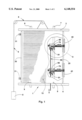
- FIG. 1 is a frontal schematic view of the device of the present invention for accommodating a planiform advertising carrier
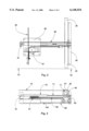
- FIG. 2 is an enlargement of cutout II of FIG. 1;
- FIG. 3 is a view along the line III--III of FIG. 2.
- the device referred to as a whole with numeral 1 has two bars 3 and 4 arranged on top of each other.
- the bars 3 and 4 are guided in parallel running guiding elements 6 and 7 arranged on the house wall.
- Bar 3 is moved relative to bar 4 by means of the cable pull referred to as a whole with numeral 5 along the guiding elements 6 and 7, whereas the cable pull is preferably connectable to a cable winch 8.
- two spring-loaded stoppers 9 are provided, against which bar 4 is tentered.
- the tentering device for the lateral tentering of advertising carrier 10 comprises two rails 20, 30, whereas rail 30 is fastened on the house wall by means of fastening device 31.
- the fastening of the advertising carrier on the rail 30 occurs in a similar way.
- the rail 20 is held by an arm 40 fastened on a carriage referred to as a whole with numeral 50.
- the carriage 50 is guided in a guiding element 60.
- the piston rod 71 of gas pressure spring 70 is engaged on the arm 40.
- the gas pressure spring 70 itself is pivotably accommodated on the bearing bracket 80 by means of an articulation 81.
- the carriage 50 is coupled with cable pull 90.
- Cable pull 90 which is deviated onto a reel 91 arranged on the bearing bracket 80, serves to move the piston rod 71 of gas pressure spring 70 in the direction of the arrow 100, hereby releasing the planiform advertising carrier 10 and guiding it in this position either into or out of the groove 21 of rail 20.
- several such tentering device designed as gas pressure springs may be provided on top of each other on big planiform advertising carriers.
- the individual cable pulls 90 are all linked together, in order to become actuated by one single cable winch.
Landscapes
- Physics & Mathematics (AREA)
- General Physics & Mathematics (AREA)
- Engineering & Computer Science (AREA)
- Theoretical Computer Science (AREA)
- Pinball Game Machines (AREA)
Abstract
The device is used for accommodating a planiform advertising carrier (10) with two bars (3,4) arranged on top of each other and for keeping the advertising carrier (10) tenterable. The advertising carrier is laterally tenterable, for lateral tentering. Further the advertising carrier (10) is provided at least on one side with a tentering device which comprises a rail (20) which takes laterally hold of the advertising carrier and a tentering device (70) by means of which the rail (20) is movable for the lateral tentering of the advertising carrier, the advertising carrier (10) being held on the other side against the tentering direction.
Description
This application is a continuation-in-part of U.S. Ser. No. 08/879,412 filed on Jun. 20, 1997 for: DEVICE FOR ACCOMMODATING A PLANIFORM CARRIER, NOW U.S. Pat. No. 5,941,001 issued Aug. 24, 1999.
1. Field of the Invention
The present invention concerns a device for accommodating a planiform advertising carrier with two bars arranged on top of each other and which keep the advertising carrier tenterable, whereas the advertising carrier is laterally tenterable.
2. Description of the Prior Art
Many different versions of large planiform advertising carriers are known; they are e.g. designed as printed foils or fabrics, and are to be fastened on house walls. Such advertising carriers often extend over several square meters. Therefore, with regard to security, great demands are made upon the fastening procedure of such an advertising carrier onto a house wall or similar structure, since such an advertising carrier must also be able to withstand a stronger wind impact.
The earlier U.S. application Ser. No. 08/879,412 discloses a device of the type mentioned above by means of which big planiform advertising carriers may be placed securely onto house walls. The advertising carrier is hereby tentered between two bars arranged on top of each other, whereas the upper bar is pulled upwards alongside the house wall where it is fastened, and whereas the other lower bar is fastened onto the house wall against the tentering direction of the upper bar. The bars keep the planiform advertising carrier under a certain pretension, preventing it from creasing, which would make a bad impression on the potential customer. U.S. Ser. No. 08/879,412 already suggested to tenter the advertising carrier also sideways by means of turnbuckles, trigger snaps and eyes in order to prevent the advertising carrier from contracting on its long sides because of the vertical tension. Experience has taught that though the arrangement of individual turnbuckles over the length of the advertising carrier does not bring the desired result, since there are still constrictions on the advertising carrier between the points of application of the individual turnbuckles, these constrictions disturb the general appearance of the advertising carrier.
Additionally, the eyes in the advertising carrier on which the turnbuckles are fastened by means of trigger snaps easily tear out, since the strain on the eyes is very strong, especially when wind is blowing.
Another disadvantage is that, in order to change the advertising carrier, the turnbuckles have to be released first before the trigger snaps, which are held by the advertising carrier's eyes, may be opened. That means that this known device for lateral tentering makes the changing of such an advertising carrier very complicated.
An object of the present invention is therefore to provide a device of the type mentioned above that makes changing of the advertising carrier with lateral tentering easily possible, whereas it should be guaranteed that even in case of stronger wind, the advertising carrier may securely be maintained on the building's facade.
The solution of this object is to provide the advertising carrier at least on one side with a tentering device for lateral tentering, the tentering device comprising a rail which takes laterally hold of the advertising carrier and a tentering device by means of which the rail for the lateral tentering of the advertising carrier is movable, the advertising carrier being held on the other, opposite side against the tentering direction. This explains that the advertising carrier is laterally tentered in that a rail, which is also laterally movable, is taking hold of the advertising carrier on one of its long sides, whereas on the other, opposite long side another rail may be provided that takes hold of the advertising carrier, this rail being fixed, that means it should not be movable along the house wall. The use of such a rail makes a crease-free tentering of the advertising carrier possible.
The tentering device is designed as being elastic, for example as a gas pressure spring, the rail standing under the pretension of such a gas pressure spring, whereas, in case of particularly big advertising carriers, several such tentering device, for example of gas pressure springs, may be arranged on top of each other in order to achieve an even tentering of the advertising carrier on a house wall. The tentering device itself is arranged on a bearing bracket, whereas the rail is advantageously provided with a carriage guided through a guiding element for the lateral slidability of the rail. Such a construction clearly shows that, when using for example a gas pressure spring as a tentering device, the carriage guided in the guiding element prevents the piston of the gas pressure spring from breaking out sideways. Together with the carriage provided with the rail, the guiding element on the contrary makes it possible for the piston of the gas spring to move absolutely horizontally.
To loosen the advertising carrier, the rail is movable by means of a cable pull against the direction of the tentering device's pretension, loosening thus the planiform advertising carrier. The cable pull, which may be arranged on the bearing bracket for the tentering device, is advantageously provided with a cable winch. That means that the cable winch pulls the rail, taking laterally hold of the planiform advertising carrier towards the bearing bracket, i.e. against the tentering direction, for example of the gas pressure spring. The thus released advertising carrier may then be taken out of the rail. The planiform advertising carrier advantageously is provided hereby at its ends with a bead or swelling for the rail to take hold of, the rail being provided with a corresponding groove into which the swelling may preferably be introduced with its end. That means that, once released, the advertising carrier may be taken out of or introduced into the rail by its swelling.
The bars receiving the planiform advertising carrier are guided through guiding elements, whereas the guiding elements are arranged on the house wall or on the building's facade. The upper bar is movable along the guiding element by means of a cable pull for tentering the advertising carrier arranged between the two bars arranged on top of each other. The device is provided with a stopper for the lower bar for the vertical tentering of the advertising carrier, the lower bar being preferably spring-loaded in order to keep the advertising carrier under pretension. Such a tentering device for tentering vertically the planiform advertising carrier is known from U.S. Pat. No. 5,941,001, and that's why it is cited as reference.
FIG. 1 is a frontal schematic view of the device of the present invention for accommodating a planiform advertising carrier;
FIG. 2 is an enlargement of cutout II of FIG. 1;
FIG. 3 is a view along the line III--III of FIG. 2.
According to FIG. 1, the device referred to as a whole with numeral 1 has two bars 3 and 4 arranged on top of each other. The bars 3 and 4 are guided in parallel running guiding elements 6 and 7 arranged on the house wall. Bar 3 is moved relative to bar 4 by means of the cable pull referred to as a whole with numeral 5 along the guiding elements 6 and 7, whereas the cable pull is preferably connectable to a cable winch 8. In order to keep the planiform advertising carrier 10, which is tenterably taken hold of by the two bars 3 and 4, under tension, two spring-loaded stoppers 9 are provided, against which bar 4 is tentered.
What is actually of interest is the device for the lateral tentering of the advertising carrier 10. This device is shown in detail in FIGS. 2 and 3. The tentering device for the lateral tentering of advertising carrier 10 comprises two rails 20, 30, whereas rail 30 is fastened on the house wall by means of fastening device 31. On the other, opposite side, there is the rail 20 that, as already explained, receives the advertising carrier 10 so that the bead or swelling 11 of advertising carrier 10 is guided in a groove 21 of rail 20. The fastening of the advertising carrier on the rail 30 occurs in a similar way. The rail 20 is held by an arm 40 fastened on a carriage referred to as a whole with numeral 50. The carriage 50 is guided in a guiding element 60. The piston rod 71 of gas pressure spring 70 is engaged on the arm 40. The gas pressure spring 70 itself is pivotably accommodated on the bearing bracket 80 by means of an articulation 81.
The carriage 50 is coupled with cable pull 90. Cable pull 90, which is deviated onto a reel 91 arranged on the bearing bracket 80, serves to move the piston rod 71 of gas pressure spring 70 in the direction of the arrow 100, hereby releasing the planiform advertising carrier 10 and guiding it in this position either into or out of the groove 21 of rail 20. As may be seen in FIG. 1, several such tentering device designed as gas pressure springs may be provided on top of each other on big planiform advertising carriers. In this case, the individual cable pulls 90 are all linked together, in order to become actuated by one single cable winch.
Claims (16)
1. Device for accommodating a, and for attachment to a, planiform advertising carrier (10) between two bars (3,4) arranged on top of each other and which keep the advertising carrier (10) tenterable between the two bars (3,4), said advertising carrier being laterally tenterable, and,
characterized in that, for lateral tentering, the advertising carrier (10) is provided, at least on one side, with a tentering device, the tentering device comprising a rail (20) which takes lateral hold of the advertising carrier and a tentering means (70) by means of which the rail (20) is movable for the lateral tentering of the advertising carrier, the advertising carrier (10) being held on the side opposite said tentering means against the direction of a tentering force of said tentering means, and said rail (20) being movable against the direction of said tentering force of said tentering means (70). thereby to provide loosening of the planiform advertising carrier (10).
2. Device according to claim 1,
characterized in that, on the side opposite said tentering means, the advertising carrier (10) is receivable by a rail (30) by which the advertising carrier (10) is fastened.
3. Device according to claim 1,
characterized in that the tentering means (70) are elastic.
4. Device according to claim 3,
characterized in that the tentering means is designed as a gas pressure spring (70).
5. Device according to claim 3,
characterized in that the tentering means (70) is arranged on a bearing bracket (80).
6. Device according to claim 1,
characterized in that the rail (20) is provided with a carriage (50) for the lateral slidability of the rail (20), the carriage being guided by a guiding element (60).
7. Device according to claim 1, characterized in that the rail (20) is movable by means of a cable pull (90) against the direction of the tentering force of the tentering means (70), thereby to loosen the planiform advertising carrier (10).
8. Device according to claim 7,
characterized in that the cable pull (90) is accommodated on the bearing bracket (80).
9. Device according to claim 7,
characterized in that the cable pull (90) is provided with a cable winch.
10. Device according to claim 1 in combination with a planiform advertising carrier,
characterized in that the planiform advertising carrier (10) is provided on each side with an elongate swelling or bead (11) for engaging the rail (20), and the rail (20) being provided with a corresponding groove (21) into which the swelling or bead (11) may be introduced.
11. Device according to claim 10,
characterized in that the swelling (11) is introducible by its end into the groove (21) of rail (20).
12. Device according to claim 1 in combination with guiding elements (6,7),
characterized in that the bars (3,4) receiving the planiform advertising carrier (10) are guided through said guiding elements (6,7).
13. Device according to claim 12,
characterized in that the upper bar (3) is movable along the guiding elements (6,7) by means of a cable pull (5) for tentering the advertising carrier (10) arranged between the two bars (3,4) accommodated on top of each other.
14. Device according to claim 12,
characterized in that the device (1) is provided with a stopper (9) for the lower bar (4).
15. Device according to claim 14,
characterized in that the stopper (9) is spring-loaded.
16. Device according to claim 1 including moving means for moving said rail against the tentering force of said tentering means, thereby to provide a loosening of said planiform advertising carrier.
Priority Applications (1)
| Application Number | Priority Date | Filing Date | Title |
|---|---|---|---|
| US09/174,339 US6148554A (en) | 1997-06-20 | 1998-10-19 | Device for accommodating a planiform advertising carrier |
Applications Claiming Priority (6)
| Application Number | Priority Date | Filing Date | Title |
|---|---|---|---|
| US08/879,412 US5941001A (en) | 1995-10-23 | 1997-06-20 | Device for accomodating a planiform advertising carrier |
| DE29812658 | 1998-07-16 | ||
| DE29812658U | 1998-07-16 | ||
| DE29813483U DE29813483U1 (en) | 1998-07-16 | 1998-07-29 | Device for receiving a flat advertising medium |
| DE29813483U | 1998-07-29 | ||
| US09/174,339 US6148554A (en) | 1997-06-20 | 1998-10-19 | Device for accommodating a planiform advertising carrier |
Related Parent Applications (1)
| Application Number | Title | Priority Date | Filing Date |
|---|---|---|---|
| US08/879,412 Continuation-In-Part US5941001A (en) | 1995-10-23 | 1997-06-20 | Device for accomodating a planiform advertising carrier |
Publications (1)
| Publication Number | Publication Date |
|---|---|
| US6148554A true US6148554A (en) | 2000-11-21 |
Family
ID=27220133
Family Applications (1)
| Application Number | Title | Priority Date | Filing Date |
|---|---|---|---|
| US09/174,339 Expired - Fee Related US6148554A (en) | 1997-06-20 | 1998-10-19 | Device for accommodating a planiform advertising carrier |
Country Status (1)
| Country | Link |
|---|---|
| US (1) | US6148554A (en) |
Cited By (5)
| Publication number | Priority date | Publication date | Assignee | Title |
|---|---|---|---|---|
| US20040034822A1 (en) * | 2002-05-23 | 2004-02-19 | Benoit Marchand | Implementing a scalable, dynamic, fault-tolerant, multicast based file transfer and asynchronous file replication protocol |
| US20040194361A1 (en) * | 2003-04-02 | 2004-10-07 | Christopher Furlan | Up-and-down display sign |
| US20050188571A1 (en) * | 2004-02-26 | 2005-09-01 | David Wilson | Elevated sign system with lowering mechanism to enable ground level servicing |
| US20070209257A1 (en) * | 2006-01-04 | 2007-09-13 | Britten Paul J | Apparatus for raising and lowering a banner that maintains the banner tensioned |
| US20170236460A1 (en) * | 2014-08-26 | 2017-08-17 | Urban Storm Management Limited | Winch for poster hoarding |
Citations (4)
| Publication number | Priority date | Publication date | Assignee | Title |
|---|---|---|---|---|
| US5555659A (en) * | 1994-08-19 | 1996-09-17 | Dinaco, Inc. | Apparatus for mounting flexible banners |
| US5845423A (en) * | 1996-01-25 | 1998-12-08 | Hicks; Charles H. | Advetising substrate attachable to trucks |
| US5893226A (en) * | 1997-11-04 | 1999-04-13 | Sophocleous; Sophocles S. | Assistance summoning device |
| US5941001A (en) * | 1995-10-23 | 1999-08-24 | Dietrich; Thomas | Device for accomodating a planiform advertising carrier |
-
1998
- 1998-10-19 US US09/174,339 patent/US6148554A/en not_active Expired - Fee Related
Patent Citations (4)
| Publication number | Priority date | Publication date | Assignee | Title |
|---|---|---|---|---|
| US5555659A (en) * | 1994-08-19 | 1996-09-17 | Dinaco, Inc. | Apparatus for mounting flexible banners |
| US5941001A (en) * | 1995-10-23 | 1999-08-24 | Dietrich; Thomas | Device for accomodating a planiform advertising carrier |
| US5845423A (en) * | 1996-01-25 | 1998-12-08 | Hicks; Charles H. | Advetising substrate attachable to trucks |
| US5893226A (en) * | 1997-11-04 | 1999-04-13 | Sophocleous; Sophocles S. | Assistance summoning device |
Cited By (7)
| Publication number | Priority date | Publication date | Assignee | Title |
|---|---|---|---|---|
| US20040034822A1 (en) * | 2002-05-23 | 2004-02-19 | Benoit Marchand | Implementing a scalable, dynamic, fault-tolerant, multicast based file transfer and asynchronous file replication protocol |
| US20040194361A1 (en) * | 2003-04-02 | 2004-10-07 | Christopher Furlan | Up-and-down display sign |
| US7000344B2 (en) | 2003-04-02 | 2006-02-21 | Christopher Furlan | Up-and-down display sign |
| US20050188571A1 (en) * | 2004-02-26 | 2005-09-01 | David Wilson | Elevated sign system with lowering mechanism to enable ground level servicing |
| US7121029B2 (en) | 2004-02-26 | 2006-10-17 | David Wilson | Elevated sign system with lowering mechanism to enable ground level servicing |
| US20070209257A1 (en) * | 2006-01-04 | 2007-09-13 | Britten Paul J | Apparatus for raising and lowering a banner that maintains the banner tensioned |
| US20170236460A1 (en) * | 2014-08-26 | 2017-08-17 | Urban Storm Management Limited | Winch for poster hoarding |
Similar Documents
| Publication | Publication Date | Title |
|---|---|---|
| US6148554A (en) | Device for accommodating a planiform advertising carrier | |
| BE901306A (en) | STORE FOR LUCARNE. | |
| MX9601177A (en) | Roll-up door. | |
| EP1151903A3 (en) | Chair for an aerial ropeway | |
| PL334923A1 (en) | Versatile system for mounting and guiding in parallel relationship a window shading apparatus | |
| KR900700684A (en) | Clamp device | |
| US5941001A (en) | Device for accomodating a planiform advertising carrier | |
| KR840007814A (en) | Drapery Support and Crossing System | |
| DE59009898D1 (en) | Supporting structure for a suspended ceiling and suspended ceiling. | |
| EP0838241A3 (en) | Thermally activated separation device, particularly for fire protection installations | |
| US5884779A (en) | Hanging rack apparatus for printed circuit panels | |
| GB2272426A (en) | Container for mounting on a vehicle | |
| EP0972681A3 (en) | Arrangement system for receiving articles | |
| DK345289D0 (en) | DEVICE FOR CLOSING CLIPS BY LOCKING DOORS | |
| GB2273867A (en) | A hanger | |
| SI9500032A (en) | Suspension arrangement for windows, doors or similar | |
| EP0260800A3 (en) | Rucksack frame fastening means | |
| DK0585990T3 (en) | Locking and bracing system for the rear door frame of trucks | |
| US926630A (en) | Shade-hanger. | |
| US5779204A (en) | Workstation for door | |
| FR2347207A1 (en) | Suspension filing system folder supports - are plastics cross pieces recessed for locking bars, with locating pegs through folder | |
| SU1237500A1 (en) | Vehicle stake | |
| SU1369948A1 (en) | Vehicle for carrying sail boards | |
| GB2352765A (en) | Clamping unit for securing a ladder or other load on a vehicle roof rack | |
| GB2257353A (en) | Hangers |
Legal Events
| Date | Code | Title | Description |
|---|---|---|---|
| FEPP | Fee payment procedure |
Free format text: PAYOR NUMBER ASSIGNED (ORIGINAL EVENT CODE: ASPN); ENTITY STATUS OF PATENT OWNER: SMALL ENTITY |
|
| REMI | Maintenance fee reminder mailed | ||
| LAPS | Lapse for failure to pay maintenance fees | ||
| STCH | Information on status: patent discontinuation |
Free format text: PATENT EXPIRED DUE TO NONPAYMENT OF MAINTENANCE FEES UNDER 37 CFR 1.362 |
|
| FP | Lapsed due to failure to pay maintenance fee |
Effective date: 20041121 |