US6148517A - Repair of turbine exhaust case - Google Patents
Repair of turbine exhaust case Download PDFInfo
- Publication number
- US6148517A US6148517A US09/239,263 US23926399A US6148517A US 6148517 A US6148517 A US 6148517A US 23926399 A US23926399 A US 23926399A US 6148517 A US6148517 A US 6148517A
- Authority
- US
- United States
- Prior art keywords
- turbine exhaust
- exhaust case
- case
- reinforcement brace
- area
- Prior art date
- Legal status (The legal status is an assumption and is not a legal conclusion. Google has not performed a legal analysis and makes no representation as to the accuracy of the status listed.)
- Expired - Fee Related
Links
- 230000008439 repair process Effects 0.000 title claims description 11
- 230000002787 reinforcement Effects 0.000 claims abstract description 18
- 238000000034 method Methods 0.000 claims abstract description 15
- 230000007547 defect Effects 0.000 claims abstract description 6
- 239000002184 metal Substances 0.000 claims description 7
- 238000003466 welding Methods 0.000 claims description 5
- 239000000203 mixture Substances 0.000 claims description 4
- 239000000945 filler Substances 0.000 claims description 2
- 238000010438 heat treatment Methods 0.000 claims description 2
- 238000009434 installation Methods 0.000 claims 1
- 238000005336 cracking Methods 0.000 description 2
- 238000007689 inspection Methods 0.000 description 2
- 229910000831 Steel Inorganic materials 0.000 description 1
- 230000002159 abnormal effect Effects 0.000 description 1
- 230000001010 compromised effect Effects 0.000 description 1
- 238000003780 insertion Methods 0.000 description 1
- 230000037431 insertion Effects 0.000 description 1
- 239000010959 steel Substances 0.000 description 1
- 238000005382 thermal cycling Methods 0.000 description 1
Images


Classifications
-
- B—PERFORMING OPERATIONS; TRANSPORTING
- B23—MACHINE TOOLS; METAL-WORKING NOT OTHERWISE PROVIDED FOR
- B23P—METAL-WORKING NOT OTHERWISE PROVIDED FOR; COMBINED OPERATIONS; UNIVERSAL MACHINE TOOLS
- B23P6/00—Restoring or reconditioning objects
- B23P6/002—Repairing turbine components, e.g. moving or stationary blades, rotors
- B23P6/005—Repairing turbine components, e.g. moving or stationary blades, rotors using only replacement pieces of a particular form
-
- B—PERFORMING OPERATIONS; TRANSPORTING
- B23—MACHINE TOOLS; METAL-WORKING NOT OTHERWISE PROVIDED FOR
- B23P—METAL-WORKING NOT OTHERWISE PROVIDED FOR; COMBINED OPERATIONS; UNIVERSAL MACHINE TOOLS
- B23P15/00—Making specific metal objects by operations not covered by a single other subclass or a group in this subclass
-
- F—MECHANICAL ENGINEERING; LIGHTING; HEATING; WEAPONS; BLASTING
- F05—INDEXING SCHEMES RELATING TO ENGINES OR PUMPS IN VARIOUS SUBCLASSES OF CLASSES F01-F04
- F05B—INDEXING SCHEME RELATING TO WIND, SPRING, WEIGHT, INERTIA OR LIKE MOTORS, TO MACHINES OR ENGINES FOR LIQUIDS COVERED BY SUBCLASSES F03B, F03D AND F03G
- F05B2230/00—Manufacture
- F05B2230/80—Repairing, retrofitting or upgrading methods
-
- Y—GENERAL TAGGING OF NEW TECHNOLOGICAL DEVELOPMENTS; GENERAL TAGGING OF CROSS-SECTIONAL TECHNOLOGIES SPANNING OVER SEVERAL SECTIONS OF THE IPC; TECHNICAL SUBJECTS COVERED BY FORMER USPC CROSS-REFERENCE ART COLLECTIONS [XRACs] AND DIGESTS
- Y10—TECHNICAL SUBJECTS COVERED BY FORMER USPC
- Y10T—TECHNICAL SUBJECTS COVERED BY FORMER US CLASSIFICATION
- Y10T29/00—Metal working
- Y10T29/49—Method of mechanical manufacture
- Y10T29/49316—Impeller making
- Y10T29/49318—Repairing or disassembling
-
- Y—GENERAL TAGGING OF NEW TECHNOLOGICAL DEVELOPMENTS; GENERAL TAGGING OF CROSS-SECTIONAL TECHNOLOGIES SPANNING OVER SEVERAL SECTIONS OF THE IPC; TECHNICAL SUBJECTS COVERED BY FORMER USPC CROSS-REFERENCE ART COLLECTIONS [XRACs] AND DIGESTS
- Y10—TECHNICAL SUBJECTS COVERED BY FORMER USPC
- Y10T—TECHNICAL SUBJECTS COVERED BY FORMER US CLASSIFICATION
- Y10T29/00—Metal working
- Y10T29/49—Method of mechanical manufacture
- Y10T29/49316—Impeller making
- Y10T29/4932—Turbomachine making
- Y10T29/49321—Assembling individual fluid flow interacting members, e.g., blades, vanes, buckets, on rotary support member
-
- Y—GENERAL TAGGING OF NEW TECHNOLOGICAL DEVELOPMENTS; GENERAL TAGGING OF CROSS-SECTIONAL TECHNOLOGIES SPANNING OVER SEVERAL SECTIONS OF THE IPC; TECHNICAL SUBJECTS COVERED BY FORMER USPC CROSS-REFERENCE ART COLLECTIONS [XRACs] AND DIGESTS
- Y10—TECHNICAL SUBJECTS COVERED BY FORMER USPC
- Y10T—TECHNICAL SUBJECTS COVERED BY FORMER US CLASSIFICATION
- Y10T29/00—Metal working
- Y10T29/49—Method of mechanical manufacture
- Y10T29/49718—Repairing
- Y10T29/49721—Repairing with disassembling
- Y10T29/4973—Replacing of defective part
Definitions
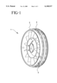
- FIG. 1 is a perspective view of a turbine exhaust case
- FIG. 2 is a partial top view of the exhaust case of FIG. 1;
- FIG. 3 is a sectional view along line 3--3 of FIG. 2 with the mounting lug deleted.
- the concept of the repair process of this invention is that the reinforcement brace reduces the localized stress concentration experienced by the case wall adjacent to the mount lugs in mounting flanges during normal thermal cycling of the engine which will prevent the occurrence of circumferential cracking. Further, the additional strength of the brace will reduce the localized stress of the mount area case wall during an abnormal occurrence such as a fan blade out or rotor seizure.
- FIG. 1 shows a turbine exhaust case 1 of a JT9D gas turbine engine having two mounting flanges 2 and 3 on the outside of the case wall 4 which are used for attaching the turbine exhaust case to a rear engine mount (not shown).
- FIG. 2 is a partial top view of FIG. 1 showing the mounting flanges 2 and 3 with the mount lugs 10 secured through the mounting flanges.
- FIG. 3 is a sectional view along line 3--3 from FIG. 2.
- FIG. 3 shows the R-Rail mounting flange 2 and S-Rail mounting flange 3 each having therein horizontal mount pinholes 5 and 6 respectively, for insertion of the mount lugs 10 shown in FIG. 2.
- the horizontal mount area 7 is the area of the case wall 4 adjacent to and between the horizontal mount pinholes 5 and 6 in the two mounting flanges 2 and 3.
- the process of this invention involves first inspecting the horizontal mount area 7 of the turbine exhaust case 1. Any defects found in the inspection are weld repaired, typically by TIG welding, preferably using a filler metal of the same composition as the turbine exhaust case, which can be a martensetic steel, e.g. AMS 5616. Then a reinforcement brace 8 is installed onto the inside of the case wall 4 in the horizontal mount area 7. The brace 8 overlaps an area under one mounting flange 2 and extends to and overlaps an area under a second mounting flange 3.
- Additional steps to be carried out include x-ray and fluorescent penetrant inspection of the weld repair and repair of any defects found in the weld. Following the repair a heat treatment is carried out in a vacuum furnace to reaustenitize and temper the turbine exhaust case, e.g. hold case at 1850° F. for 2 hours, cool to 600° F. for 30 minutes and temper at 1050° F. for 2 hours.
- a heat treatment is carried out in a vacuum furnace to reaustenitize and temper the turbine exhaust case, e.g. hold case at 1850° F. for 2 hours, cool to 600° F. for 30 minutes and temper at 1050° F. for 2 hours.
- the reinforcement brace is a metal plate preferably of the same composition as the turbine exhaust case.
- the brace extends at least about 0.5 inches beyond the mounting flange and has a curvature which matches the inside of the exhaust case.
- the brace has a length of about 6 to 7 inches, a width of about 2 to 5 inches and a thickness of 0.080 to 0.250 inches.
- the brace is installed by welding, e.g. TIG welding and typically two braces are installed on each JT9D exhaust case.
- the edges of the reinforcement brace can be tapered for aerodynamic stability.
Landscapes
- Engineering & Computer Science (AREA)
- Mechanical Engineering (AREA)
- Arc Welding In General (AREA)
- Butt Welding And Welding Of Specific Article (AREA)
- Heat Treatment Of Articles (AREA)
Abstract
Description
Claims (12)
Priority Applications (9)
| Application Number | Priority Date | Filing Date | Title |
|---|---|---|---|
| US09/239,263 US6148517A (en) | 1999-01-29 | 1999-01-29 | Repair of turbine exhaust case |
| EP99972431A EP1154876A4 (en) | 1999-01-29 | 1999-12-03 | Repair of turbine exhaust case |
| JP2000595814A JP2002535555A (en) | 1999-01-29 | 1999-12-03 | How to repair the turbine exhaust case |
| PCT/US1999/028819 WO2000044525A1 (en) | 1999-01-29 | 1999-12-03 | Repair of turbine exhaust case |
| KR1020017009413A KR20010101722A (en) | 1999-01-29 | 1999-12-03 | Repair of turbine exhaust case |
| IL14425799A IL144257A0 (en) | 1999-01-29 | 1999-12-03 | Repair of turbine exhaust case |
| CA002358941A CA2358941A1 (en) | 1999-01-29 | 1999-12-03 | Repair of turbine exhaust case |
| AU41643/00A AU4164300A (en) | 1999-01-29 | 1999-12-03 | Repair of turbine exhaust case |
| CN99815906A CN1334760A (en) | 1999-01-29 | 1999-12-03 | Repair of turbine exhaust case |
Applications Claiming Priority (1)
| Application Number | Priority Date | Filing Date | Title |
|---|---|---|---|
| US09/239,263 US6148517A (en) | 1999-01-29 | 1999-01-29 | Repair of turbine exhaust case |
Publications (1)
| Publication Number | Publication Date |
|---|---|
| US6148517A true US6148517A (en) | 2000-11-21 |
Family
ID=22901378
Family Applications (1)
| Application Number | Title | Priority Date | Filing Date |
|---|---|---|---|
| US09/239,263 Expired - Fee Related US6148517A (en) | 1999-01-29 | 1999-01-29 | Repair of turbine exhaust case |
Country Status (9)
| Country | Link |
|---|---|
| US (1) | US6148517A (en) |
| EP (1) | EP1154876A4 (en) |
| JP (1) | JP2002535555A (en) |
| KR (1) | KR20010101722A (en) |
| CN (1) | CN1334760A (en) |
| AU (1) | AU4164300A (en) |
| CA (1) | CA2358941A1 (en) |
| IL (1) | IL144257A0 (en) |
| WO (1) | WO2000044525A1 (en) |
Cited By (7)
| Publication number | Priority date | Publication date | Assignee | Title |
|---|---|---|---|---|
| US6615470B2 (en) * | 1997-12-15 | 2003-09-09 | General Electric Company | System and method for repairing cast articles |
| US20060059674A1 (en) * | 2004-09-23 | 2006-03-23 | Williams Nicholas A | Procedure for replacement of acoustic liner in integrated exhaust duct muffler for use with airborne auxiliary power units |
| US20060243709A1 (en) * | 2003-02-28 | 2006-11-02 | Werner Born | Method and device for restoring and producing geometrically complex components |
| US20090071002A1 (en) * | 2007-09-18 | 2009-03-19 | United Technologies Corp. | Methods for Repairing Gas Turbine Engine Components |
| US20100275614A1 (en) * | 2009-04-30 | 2010-11-04 | Pratt & Whitney Canada Corp. | Structural reinforcement strut for gas turbine case |
| US20120301286A1 (en) * | 2010-02-10 | 2012-11-29 | Snecma | Method for repairing a flange of a housing |
| US9631517B2 (en) | 2012-12-29 | 2017-04-25 | United Technologies Corporation | Multi-piece fairing for monolithic turbine exhaust case |
Families Citing this family (1)
| Publication number | Priority date | Publication date | Assignee | Title |
|---|---|---|---|---|
| GB2553531B (en) * | 2016-09-07 | 2019-02-06 | Rolls Royce Plc | A method of attaching a projection to a thin walled component |
Family Cites Families (2)
| Publication number | Priority date | Publication date | Assignee | Title |
|---|---|---|---|---|
| US5972424A (en) * | 1998-05-21 | 1999-10-26 | United Technologies Corporation | Repair of gas turbine engine component coated with a thermal barrier coating |
| US6042880A (en) * | 1998-12-22 | 2000-03-28 | General Electric Company | Renewing a thermal barrier coating system |
-
1999
- 1999-01-29 US US09/239,263 patent/US6148517A/en not_active Expired - Fee Related
- 1999-12-03 JP JP2000595814A patent/JP2002535555A/en not_active Withdrawn
- 1999-12-03 EP EP99972431A patent/EP1154876A4/en not_active Withdrawn
- 1999-12-03 CN CN99815906A patent/CN1334760A/en active Pending
- 1999-12-03 WO PCT/US1999/028819 patent/WO2000044525A1/en not_active Application Discontinuation
- 1999-12-03 KR KR1020017009413A patent/KR20010101722A/en not_active Application Discontinuation
- 1999-12-03 AU AU41643/00A patent/AU4164300A/en not_active Abandoned
- 1999-12-03 CA CA002358941A patent/CA2358941A1/en not_active Abandoned
- 1999-12-03 IL IL14425799A patent/IL144257A0/en unknown
Non-Patent Citations (4)
| Title |
|---|
| Pratt & Whitney Aircraft JT3D 7 Overhaul Manual: Turbine Exhaust Case REPAIR 2, 72 54 1 (2 pages, dated prior to Jan. 29, 1998); Turbine Exhaust Case REPAIR 3, 72 54 1 ( pp. 401 409, dated Mar. 1, 1978); and Turbine Exhaust Case REPAIR 10, 72 54 1 (pp. 401 407, dated Aug. 15, 1985). * |
| Pratt & Whitney Aircraft JT3D-7 Overhaul Manual: Turbine Exhaust Case REPAIR-2, 72-54-1 (2 pages, dated prior to Jan. 29, 1998); Turbine Exhaust Case REPAIR-3, 72-54-1 ( pp. 401-409, dated Mar. 1, 1978); and Turbine Exhaust Case REPAIR-10, 72-54-1 (pp. 401-407, dated Aug. 15, 1985). |
| Pratt & Whitney Service Bulletin No. 6077 (pp. 2 6, Aug. 1, 1992). * |
| Pratt & Whitney Service Bulletin No. 6077 (pp. 2-6, Aug. 1, 1992). |
Cited By (11)
| Publication number | Priority date | Publication date | Assignee | Title |
|---|---|---|---|---|
| US6615470B2 (en) * | 1997-12-15 | 2003-09-09 | General Electric Company | System and method for repairing cast articles |
| US20060243709A1 (en) * | 2003-02-28 | 2006-11-02 | Werner Born | Method and device for restoring and producing geometrically complex components |
| US20060059674A1 (en) * | 2004-09-23 | 2006-03-23 | Williams Nicholas A | Procedure for replacement of acoustic liner in integrated exhaust duct muffler for use with airborne auxiliary power units |
| US7448133B2 (en) | 2004-09-23 | 2008-11-11 | Honeywell International Inc. | Procedure for replacement of acoustic liner in integrated exhaust duct muffler for use with airborne auxiliary power units |
| US20090071002A1 (en) * | 2007-09-18 | 2009-03-19 | United Technologies Corp. | Methods for Repairing Gas Turbine Engine Components |
| US20100275614A1 (en) * | 2009-04-30 | 2010-11-04 | Pratt & Whitney Canada Corp. | Structural reinforcement strut for gas turbine case |
| US8408011B2 (en) | 2009-04-30 | 2013-04-02 | Pratt & Whitney Canada Corp. | Structural reinforcement strut for gas turbine case |
| US8561415B2 (en) | 2009-04-30 | 2013-10-22 | Pratt & Whitney Canada Corp. | Method of making a structural reinforcement strut for a turbine exhaust case of a gas turbine engine |
| US20120301286A1 (en) * | 2010-02-10 | 2012-11-29 | Snecma | Method for repairing a flange of a housing |
| US9533383B2 (en) * | 2010-02-10 | 2017-01-03 | Snecma | Method for repairing a flange of a housing |
| US9631517B2 (en) | 2012-12-29 | 2017-04-25 | United Technologies Corporation | Multi-piece fairing for monolithic turbine exhaust case |
Also Published As
| Publication number | Publication date |
|---|---|
| EP1154876A1 (en) | 2001-11-21 |
| KR20010101722A (en) | 2001-11-14 |
| IL144257A0 (en) | 2002-05-23 |
| CA2358941A1 (en) | 2000-08-03 |
| JP2002535555A (en) | 2002-10-22 |
| AU4164300A (en) | 2000-08-18 |
| WO2000044525A1 (en) | 2000-08-03 |
| EP1154876A4 (en) | 2002-04-03 |
| CN1334760A (en) | 2002-02-06 |
Similar Documents
| Publication | Publication Date | Title |
|---|---|---|
| US11517981B2 (en) | Laser powder deposition weld rework for gas turbine engine non-fusion weldable nickel castings | |
| US20080216300A1 (en) | Splitter fairing repair | |
| US7244320B2 (en) | Methods for repairing gas turbine engine components | |
| EP0934795A2 (en) | In-situ repair method for a turbomachinery component | |
| US20090049689A1 (en) | Method repair of turbine blade tip | |
| US7980813B2 (en) | Fan outlet guide vane shroud insert repair | |
| US6148517A (en) | Repair of turbine exhaust case | |
| US20080025842A1 (en) | Turbine vane with removable platform inserts | |
| US20100180417A1 (en) | Replacement of part of engine case with dissimilar material | |
| JP4588318B2 (en) | Method for replacing a portion of a turbine shroud support | |
| US20160236298A1 (en) | Laser powder deposition weld rework for gas turbine engine non-fusion weldable nickel castings | |
| US8230569B2 (en) | Repair of case flange with bolt holes | |
| US8662819B2 (en) | Apparatus and method for preventing cracking of turbine engine cases | |
| US8235664B2 (en) | Liner in a cooling channel of a turbine blade | |
| US8367964B2 (en) | Repair methods involving conductive heat resistance welding | |
| CN110711938A (en) | Laser welding method for silencer and cylinder cover | |
| US9470102B2 (en) | Crack resistant turbine vane and method for vane containment cap attachment | |
| KR102707751B1 (en) | Repair arrangement and gas turbine | |
| JP5149612B2 (en) | Method for manufacturing a combustor liner replacement panel | |
| JP2012519791A (en) | Equipment for repairing aircraft engine casing holders | |
| RU2419527C1 (en) | Method of repairing turbo machine blade integrated disk (blisk) | |
| JP2002364382A (en) | Material degradation and damage recovering treatment method for prime mover part | |
| Bossmann et al. | Probabilistic Lifetime Prediction of Thermal Barrier Coating Systems Depending on Manufacturing Scatter | |
| JP2000319710A (en) | Method for repairing iron shell of blast furnace | |
| JPH11230018A (en) | Method for repairing stay vane |
Legal Events
| Date | Code | Title | Description |
|---|---|---|---|
| AS | Assignment |
Owner name: CHROMALLOY GAS TURBINE CORPORATION, TEXAS Free format text: ASSIGNMENT OF ASSIGNORS INTEREST;ASSIGNORS:JOHNSON, BRUCE;BLUMANSTOCK, BEN;REEL/FRAME:009778/0158 Effective date: 19990216 |
|
| REMI | Maintenance fee reminder mailed | ||
| LAPS | Lapse for failure to pay maintenance fees | ||
| STCH | Information on status: patent discontinuation |
Free format text: PATENT EXPIRED DUE TO NONPAYMENT OF MAINTENANCE FEES UNDER 37 CFR 1.362 |
|
| FP | Lapsed due to failure to pay maintenance fee |
Effective date: 20041121 |
|
| AS | Assignment |
Owner name: BARCLAYS BANK PLC, NEW YORK Free format text: NOTICE AND CONFIRMATION OF GRANT OF SECURITY INTEREST IN PATENTS;ASSIGNOR:CHROMALLOY GAS TURBINE LLC;REEL/FRAME:029626/0158 Effective date: 20121219 |