US6147743A - Method and apparatus for providing zoom and crop functions in a photographic print copying station - Google Patents
Method and apparatus for providing zoom and crop functions in a photographic print copying station Download PDFInfo
- Publication number
- US6147743A US6147743A US09/144,392 US14439298A US6147743A US 6147743 A US6147743 A US 6147743A US 14439298 A US14439298 A US 14439298A US 6147743 A US6147743 A US 6147743A
- Authority
- US
- United States
- Prior art keywords
- mask
- photographic print
- copying station
- area
- copying
- Prior art date
- Legal status (The legal status is an assumption and is not a legal conclusion. Google has not performed a legal analysis and makes no representation as to the accuracy of the status listed.)
- Expired - Lifetime
Links
Images
Classifications
-
- G—PHYSICS
- G03—PHOTOGRAPHY; CINEMATOGRAPHY; ANALOGOUS TECHNIQUES USING WAVES OTHER THAN OPTICAL WAVES; ELECTROGRAPHY; HOLOGRAPHY
- G03B—APPARATUS OR ARRANGEMENTS FOR TAKING PHOTOGRAPHS OR FOR PROJECTING OR VIEWING THEM; APPARATUS OR ARRANGEMENTS EMPLOYING ANALOGOUS TECHNIQUES USING WAVES OTHER THAN OPTICAL WAVES; ACCESSORIES THEREFOR
- G03B27/00—Photographic printing apparatus
- G03B27/32—Projection printing apparatus, e.g. enlarger, copying camera
- G03B27/52—Details
Definitions
- the present invention relates to the field of manually operated photographic print copying stations, and in particular to a method and apparatus for providing zoom and crop functions in such stations.
- Photographic print copying stations whereby a customer can scan a color or black and white picture and produce a copy of the picture are well known.
- An example of such a copying station is the Kodak IMAGE MAGIC Picture Maker, manufactured by the Eastman Kodak Company, Rochester, N.Y., which includes a flat bed scanner, a monitor having a touch screen input device, an image processing computer, and a color thermal printer.
- a menu with instructions is displayed on the touch screen.
- the customer is instructed to indicate the size of the original picture and then to select a print layout.
- Print layouts can be for example one 8 ⁇ 10, two 5 ⁇ 7's, or a number of wallet size images arranged on an 8 ⁇ 10 sheet.
- the customer is instructed to place the picture on the bed of the scanner and activate a button on the touch screen to begin scanning.
- the scanned image is then displayed on the touch screen and the customer can apply a set of editing tools, including zoom and crop. For zoom and crop, a red box is shown on the displayed image. The size, orientation and location of the box can be manipulated using buttons on the touch screen.
- the customer is finished with editing the image, she is instructed to verify the result and to print the image by activating a button on the touch screen.
- a photographic print copying station that includes a scanner for scanning a photographic print and a mask associated with the scanner.
- the mask is placed over the photographic print to indicate an area of the print for copying and an operator control is provided on the copying station for selecting a desired copy size.
- the copying station includes a logic and control circuit that responds to the signal produced by the scanner to recognize the mask area, separate the image area from the mask area, and resize the image area to the selected copy size. The resized image is then printed by a printer in the copying station.
- the copying station of the present invention has the advantage of being less expensive to manufacture than the prior art photographic print copying station. It is also smaller, lighter, and requires less maintenance since it does not include a monitor and touch screen.
- the copying station of the present invention has the further advantage that while one customer is scanning a picture and printing a copy, other customers may be engaged in aligning their pictures in a mask, thereby increasing the throughput of the copying station.
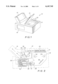
- FIG. 1 is perspective view of a photographic copying station according to the present invention
- FIG. 2 is a schematic block diagram of the photographic copying station shown in FIG. 1;
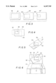
- FIG. 3 is a top view of a set of masks useful with the present invention.
- FIG. 4 is a schematic diagram illustrating the use of one of the masks in the set
- FIG. 5 is top view of an adjustable mask useful with the present invention.
- FIG. 6 is a front perspective view of a photographic copying machine according to the present invention, wherein an adjustable mask of the type shown in FIG. 5 is built into the cover of the apparatus;
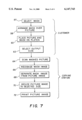
- FIG. 7 is a flow chart showing the operation of the photographic copying station according to the present invention.
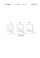
- FIG. 8 is a top view of an alternative set of masks having oval shaped openings for providing an artistic effect in the copied image.
- a photographic print copying station generally designated 10, according to the present invention is shown.
- the copying station 10 includes a platen 12 having a cover 14, a print eject tray 16, a media supply door 18, and a set of control buttons 20.
- a separate display device is not used to assist the user in zooming and cropping a print, thereby saving the manufacturing expense of adding a monitor and touch sensitive screen to the station.
- the necessary visual feedback is provided to the user and to the copying station electronics by an inexpensive physical mask which is placed over the print, exposing only the portion of the picture which is to be printed.
- the control electronics in the copy station recognizes the area of the mask, separates the image area from the mask area, and resizes the image area to the selected copy size. Since these functions are implemented by software in the control electronics, the marginal costs for providing the functions, plus the cost of the physical mask(s) is much less than the cost of a monitor with a touch sensitive screen, thereby significantly reducing the cost of manufacturing the copying station.
- the copying station 10 includes a scanner 22 of the type well known in the art, having transparent platen 12, an illumination source, such as a pair of flash lamps 24, a mirror 26, a lens 28, and an image sensor 30.
- Image sensor 30 may comprise for example a solid state area array image sensor such as the KAF0400 manufactured by the Eastman Kodak Company, Rochester, N.Y.
- a color filter wheel 31 is positioned with respect to sensor 30 and rotated to provide sequential red, green and blue separation images to sensor 30.
- the image signals generated by the image sensor 30 are processed by signal processing and control electronics 32 as will be described below.
- the signal processing and control electronics 32 includes, for example, a micro processor and associated memory for performing digital image signal manipulations.
- the signal processing and control electronics 32 receives control signals from control buttons 20 and supplies the processed image signals to a color printer 34.
- the color printer 34 is for example, a thermal printer of the type well known in the art, having a paper supply 36, a thermal print dye donor supply 38 and take-up 40, a print drum 42, and a thermal print head 44.
- the color printer 34 ejects the finished print into the print eject tray 16.
- FIGS. 3 and 4 the cropping mask according to the present invention will now be described.
- a series of masks 46, 46', 46" may be provided, each having a different sized cropping aperture 48, 48', 48".
- the cropping mask may be made for example from cardboard, or sheet plastic and can be white, or some unnatural color to assist the signal processing electronics in separating the image of the mask from the selected image area of the picture.
- One well known process for separating an object from a background is called the chroma key process, wherein a blue screen is placed behind actors in a scene, and in subsequent processing, the background is separated from the actors by recognizing the color of the background.
- the minimum size of the cropping aperture 48 is limited by the resolution of the scanner 22, since the output print cannot be enlarged beyond a certain point without unacceptable loss of sharpness.
- the cropping aperture has the same aspect ratio as the selected desired copy size.
- the mask 46 is placed over the picture 50 and arranged such that the desired part of the picture shows through the cropping aperture 48.
- the picture with the mask in place is then placed face down on the platen 12 of the copying station 10, with the mask between the picture and the platen, and the cover 14 is closed over the picture and mask.
- the operator then uses one of the buttons 20 to select the desired size of the output and to initiate the copying of the selected portion of the picture.
- the color of the mask may indicate to the copy station electronics that a desired output has been selected.
- the interface may be further simplified in that the selection of the mask of appropriate color may also select the output format. This is advantageous since standard output sizes have differing aspect ratios, and therefore the openings in the masks should match the aspect ratio of the desired output.
- a bar code or other machine readable code may be visible on the face of the mask to provide information to the computer as to the desired output format. This means can also provide the advantages described above for the colored masks.
- FIG. 5 shows an example of such a mask, which includes a sleeve 52 having a rectangular aperture 54 arranged at an angle to the sleeve.
- a slide 56 located in the sleeve has a corresponding aperture, and when the slide 56 is displaced in the direction of arrow A, the size of the cropping aperture in the sleeve changes continuously (as shown by the dotted lines in FIG. 5) while preserving the cropping aperture proportion as the aperture size changes.
- the application of the mask to the picture can occur without the involvement of the copying station.
- other users can prepare images for copying, thereby maximizing the throughput of the copying station.
- the adjustable mask is hinged to the underside of the cover 14 of the photographic print copying station 10 by a hinge 55.
- a photographic print 53 is placed behind the mask, and the mask is adjusted to provide the cropping desired.
- the cover is then closed and the copying station is actuated.
- buttons may represent, for example, an 8 ⁇ 10, two 5 ⁇ 7's, four 4R size prints, or a page of wallet size prints.
- the control electronics signal the scanner to scan (64) the masked picture on the platen.
- the signal processing and control electronics 32 recognizes the portion of the image representing the mask (66) and separates the image area from the mask (68), using one of the well known algorithms for determining an image area from a background. Once separated, the signal processing and control electronics 32 resizes the image area to the desired output size (70) and signals the printer 34 to print (72) the finished image.
- the signal processing and control electronics 32 automatically formats the image to produce multiple copies of the selected size image on the paper.
- different shaped openings such as ovals can be provided in the masks to provide an artistic effect to the copied image.
- the oval has the same aspect ratio as the desired copy size.
- the signal processing and control electronics may also apply sharpening filters to the digital image depending on the size of the input image. Additionally, the system may scan more than once on the basis of the size of the selected area. If the resolution of the scanner is variable, a first scan at a resolution sufficient for printing without enlargement (zooming) may be used. Upon determining a relatively small image area has been presented to the scanner, the system can rescan the image at a higher resolution to facilitate enlargement. Of course, a limiting factor in the quality of the reproduction will be the resolution of the input print, however, this is not under the control of the copying station.
- a low resolution prescan unsuitable for printing might also be used to determine the desired print area.
- the scanner resolution would be increased for scanning even a full-size image, and increased more when a small area has been selected for printing by the masking process.
Landscapes
- Physics & Mathematics (AREA)
- General Physics & Mathematics (AREA)
- Editing Of Facsimile Originals (AREA)
Abstract
Description
Claims (11)
Priority Applications (1)
| Application Number | Priority Date | Filing Date | Title |
|---|---|---|---|
| US09/144,392 US6147743A (en) | 1998-08-31 | 1998-08-31 | Method and apparatus for providing zoom and crop functions in a photographic print copying station |
Applications Claiming Priority (1)
| Application Number | Priority Date | Filing Date | Title |
|---|---|---|---|
| US09/144,392 US6147743A (en) | 1998-08-31 | 1998-08-31 | Method and apparatus for providing zoom and crop functions in a photographic print copying station |
Publications (1)
| Publication Number | Publication Date |
|---|---|
| US6147743A true US6147743A (en) | 2000-11-14 |
Family
ID=22508383
Family Applications (1)
| Application Number | Title | Priority Date | Filing Date |
|---|---|---|---|
| US09/144,392 Expired - Lifetime US6147743A (en) | 1998-08-31 | 1998-08-31 | Method and apparatus for providing zoom and crop functions in a photographic print copying station |
Country Status (1)
| Country | Link |
|---|---|
| US (1) | US6147743A (en) |
Cited By (5)
| Publication number | Priority date | Publication date | Assignee | Title |
|---|---|---|---|---|
| US6320650B1 (en) * | 1999-12-20 | 2001-11-20 | Eastman Kodak Company | Positioning apparatus for image capturing apparatus |
| US20050068591A1 (en) * | 2003-09-30 | 2005-03-31 | Dobbs Michael David | Method and an apparatus for adjusting a scanning target area of an image reproduction device |
| US20050146757A1 (en) * | 2004-01-07 | 2005-07-07 | Haas William R. | Image scanner feature detection |
| US20050271782A1 (en) * | 2004-06-03 | 2005-12-08 | Lewis Churnick | Method of image cropping and location affixing for enhanced duplication reproductions on edible media |
| US20070035546A1 (en) * | 2005-08-11 | 2007-02-15 | Kim Hyun O | Animation composing vending machine |
Citations (9)
| Publication number | Priority date | Publication date | Assignee | Title |
|---|---|---|---|---|
| US4763989A (en) * | 1987-03-27 | 1988-08-16 | Christian Gregory L | Variable imaging mask for delineating the composition of a visible area |
| US4961090A (en) * | 1989-08-03 | 1990-10-02 | Xerox Corporation | Large media proportional copying system |
| US4970547A (en) * | 1990-02-20 | 1990-11-13 | Visicon, Inc. | System and method for generating and codifying photo cropping and enlargement information |
| US5045878A (en) * | 1989-07-28 | 1991-09-03 | Bernd Taeger | Cropping device |
| US5115271A (en) * | 1991-05-30 | 1992-05-19 | Hagopian James C | Cropping device for photographs and the like |
| US5173789A (en) * | 1991-07-18 | 1992-12-22 | Eastman Kodak Company | Image scanner incorporating manually operable magnification and brightness control |
| US5357313A (en) * | 1994-02-04 | 1994-10-18 | Gideon Lewin | Cropper |
| US5631747A (en) * | 1995-08-21 | 1997-05-20 | Xerox Corporation | Apparatus and method for applying trim marks to a print media sheet |
| US5796496A (en) * | 1993-09-22 | 1998-08-18 | Kabushiki Kaisha Toshiba | Image-data processing apparatus which automatically selects one of a copying function and a facsimile function based on an orientation of an original |
-
1998
- 1998-08-31 US US09/144,392 patent/US6147743A/en not_active Expired - Lifetime
Patent Citations (9)
| Publication number | Priority date | Publication date | Assignee | Title |
|---|---|---|---|---|
| US4763989A (en) * | 1987-03-27 | 1988-08-16 | Christian Gregory L | Variable imaging mask for delineating the composition of a visible area |
| US5045878A (en) * | 1989-07-28 | 1991-09-03 | Bernd Taeger | Cropping device |
| US4961090A (en) * | 1989-08-03 | 1990-10-02 | Xerox Corporation | Large media proportional copying system |
| US4970547A (en) * | 1990-02-20 | 1990-11-13 | Visicon, Inc. | System and method for generating and codifying photo cropping and enlargement information |
| US5115271A (en) * | 1991-05-30 | 1992-05-19 | Hagopian James C | Cropping device for photographs and the like |
| US5173789A (en) * | 1991-07-18 | 1992-12-22 | Eastman Kodak Company | Image scanner incorporating manually operable magnification and brightness control |
| US5796496A (en) * | 1993-09-22 | 1998-08-18 | Kabushiki Kaisha Toshiba | Image-data processing apparatus which automatically selects one of a copying function and a facsimile function based on an orientation of an original |
| US5357313A (en) * | 1994-02-04 | 1994-10-18 | Gideon Lewin | Cropper |
| US5631747A (en) * | 1995-08-21 | 1997-05-20 | Xerox Corporation | Apparatus and method for applying trim marks to a print media sheet |
Cited By (8)
| Publication number | Priority date | Publication date | Assignee | Title |
|---|---|---|---|---|
| US6320650B1 (en) * | 1999-12-20 | 2001-11-20 | Eastman Kodak Company | Positioning apparatus for image capturing apparatus |
| US20050068591A1 (en) * | 2003-09-30 | 2005-03-31 | Dobbs Michael David | Method and an apparatus for adjusting a scanning target area of an image reproduction device |
| US8441694B2 (en) * | 2003-09-30 | 2013-05-14 | Hewlett-Packard Development Company, L.P. | Method and an apparatus for adjusting a scanning target area of an image reproduction device |
| US20050146757A1 (en) * | 2004-01-07 | 2005-07-07 | Haas William R. | Image scanner feature detection |
| US7773270B2 (en) | 2004-01-07 | 2010-08-10 | Hewlett-Packard Development Company, L.P. | Image scanner feature detection |
| US20050271782A1 (en) * | 2004-06-03 | 2005-12-08 | Lewis Churnick | Method of image cropping and location affixing for enhanced duplication reproductions on edible media |
| US7528985B2 (en) * | 2004-06-03 | 2009-05-05 | Lewis Churnick | Method of image cropping and location affixing for enhanced duplication reproductions on edible media |
| US20070035546A1 (en) * | 2005-08-11 | 2007-02-15 | Kim Hyun O | Animation composing vending machine |
Similar Documents
| Publication | Publication Date | Title |
|---|---|---|
| US6940526B2 (en) | Image synthesizing apparatus | |
| US7209149B2 (en) | Image cropping and synthesizing method, and imaging apparatus | |
| US5867282A (en) | Method of combining two digitally generated images wherein one is customized in view of the other | |
| US7151617B2 (en) | Image synthesizing apparatus | |
| JPH02118680A (en) | Base color removing method for image forming device | |
| JP2001218047A (en) | Picture processor | |
| US6795209B1 (en) | Method and apparatus for modifying a hard copy image digitally in accordance with instructions provided by consumer | |
| JP3581265B2 (en) | Image processing method and apparatus | |
| US6147743A (en) | Method and apparatus for providing zoom and crop functions in a photographic print copying station | |
| JPH087384B2 (en) | Enlarged print making method | |
| JPH0895160A (en) | Film image processor | |
| JP4936035B2 (en) | Photo printing device | |
| JP2006005766A (en) | Image processing method and device | |
| JP4264070B2 (en) | Image forming method and image forming apparatus | |
| JP3769748B2 (en) | Photo printing device | |
| JPH0196634A (en) | Index photograph printing method | |
| JP2004309558A (en) | Digital photo printing equipment | |
| GB2253319A (en) | Photographic printing apparatus | |
| JP2000075415A (en) | Device and system for forming print | |
| JP2000023086A (en) | Photograph system | |
| JPH0338628A (en) | Camera and photographic printing method | |
| JP2000078338A (en) | Print preparation device and print preparation system | |
| JP2000078386A (en) | Device and system for preparing print | |
| JP2000258848A (en) | Print making system | |
| JP2004053843A (en) | Frame print system, camera and lens-fitted film used for the same |
Legal Events
| Date | Code | Title | Description |
|---|---|---|---|
| AS | Assignment |
Owner name: EASTMAN KODAK COMPANY, NEW YORK Free format text: ASSIGNMENT OF ASSIGNORS INTEREST;ASSIGNORS:FREDLUND, JOHN R.;ARCHIE, WILLIAM C.;REEL/FRAME:009429/0938 Effective date: 19980828 |
|
| STCF | Information on status: patent grant |
Free format text: PATENTED CASE |
|
| FEPP | Fee payment procedure |
Free format text: PAYOR NUMBER ASSIGNED (ORIGINAL EVENT CODE: ASPN); ENTITY STATUS OF PATENT OWNER: LARGE ENTITY |
|
| FPAY | Fee payment |
Year of fee payment: 4 |
|
| FPAY | Fee payment |
Year of fee payment: 8 |
|
| AS | Assignment |
Owner name: CITICORP NORTH AMERICA, INC., AS AGENT, NEW YORK Free format text: SECURITY INTEREST;ASSIGNORS:EASTMAN KODAK COMPANY;PAKON, INC.;REEL/FRAME:028201/0420 Effective date: 20120215 |
|
| FPAY | Fee payment |
Year of fee payment: 12 |
|
| AS | Assignment |
Owner name: WILMINGTON TRUST, NATIONAL ASSOCIATION, AS AGENT, MINNESOTA Free format text: PATENT SECURITY AGREEMENT;ASSIGNORS:EASTMAN KODAK COMPANY;PAKON, INC.;REEL/FRAME:030122/0235 Effective date: 20130322 Owner name: WILMINGTON TRUST, NATIONAL ASSOCIATION, AS AGENT, Free format text: PATENT SECURITY AGREEMENT;ASSIGNORS:EASTMAN KODAK COMPANY;PAKON, INC.;REEL/FRAME:030122/0235 Effective date: 20130322 |
|
| AS | Assignment |
Owner name: PAKON, INC., NEW YORK Free format text: RELEASE OF SECURITY INTEREST IN PATENTS;ASSIGNORS:CITICORP NORTH AMERICA, INC., AS SENIOR DIP AGENT;WILMINGTON TRUST, NATIONAL ASSOCIATION, AS JUNIOR DIP AGENT;REEL/FRAME:031157/0451 Effective date: 20130903 Owner name: EASTMAN KODAK COMPANY, NEW YORK Free format text: RELEASE OF SECURITY INTEREST IN PATENTS;ASSIGNORS:CITICORP NORTH AMERICA, INC., AS SENIOR DIP AGENT;WILMINGTON TRUST, NATIONAL ASSOCIATION, AS JUNIOR DIP AGENT;REEL/FRAME:031157/0451 Effective date: 20130903 |
|
| AS | Assignment |
Owner name: 111616 OPCO (DELAWARE) INC., NEW YORK Free format text: ASSIGNMENT OF ASSIGNORS INTEREST;ASSIGNOR:EASTMAN KODAK COMPANY;REEL/FRAME:031172/0025 Effective date: 20130903 |
|
| AS | Assignment |
Owner name: KODAK ALARIS INC., NEW YORK Free format text: CHANGE OF NAME;ASSIGNOR:111616 OPCO (DELAWARE) INC.;REEL/FRAME:031394/0001 Effective date: 20130920 |