US6145179A - Method and apparatus for shock absorber removal - Google Patents
Method and apparatus for shock absorber removal Download PDFInfo
- Publication number
- US6145179A US6145179A US09/083,990 US8399098A US6145179A US 6145179 A US6145179 A US 6145179A US 8399098 A US8399098 A US 8399098A US 6145179 A US6145179 A US 6145179A
- Authority
- US
- United States
- Prior art keywords
- bracket
- shock absorber
- removal device
- legs
- clamp
- Prior art date
- Legal status (The legal status is an assumption and is not a legal conclusion. Google has not performed a legal analysis and makes no representation as to the accuracy of the status listed.)
- Expired - Lifetime
Links
Images


Classifications
-
- B—PERFORMING OPERATIONS; TRANSPORTING
- B60—VEHICLES IN GENERAL
- B60G—VEHICLE SUSPENSION ARRANGEMENTS
- B60G15/00—Resilient suspensions characterised by arrangement, location or type of combined spring and vibration damper, e.g. telescopic type
- B60G15/02—Resilient suspensions characterised by arrangement, location or type of combined spring and vibration damper, e.g. telescopic type having mechanical spring
- B60G15/06—Resilient suspensions characterised by arrangement, location or type of combined spring and vibration damper, e.g. telescopic type having mechanical spring and fluid damper
-
- B—PERFORMING OPERATIONS; TRANSPORTING
- B25—HAND TOOLS; PORTABLE POWER-DRIVEN TOOLS; MANIPULATORS
- B25B—TOOLS OR BENCH DEVICES NOT OTHERWISE PROVIDED FOR, FOR FASTENING, CONNECTING, DISENGAGING OR HOLDING
- B25B27/00—Hand tools, specially adapted for fitting together or separating parts or objects whether or not involving some deformation, not otherwise provided for
- B25B27/0035—Hand tools, specially adapted for fitting together or separating parts or objects whether or not involving some deformation, not otherwise provided for for motor-vehicles
-
- B—PERFORMING OPERATIONS; TRANSPORTING
- B25—HAND TOOLS; PORTABLE POWER-DRIVEN TOOLS; MANIPULATORS
- B25B—TOOLS OR BENCH DEVICES NOT OTHERWISE PROVIDED FOR, FOR FASTENING, CONNECTING, DISENGAGING OR HOLDING
- B25B27/00—Hand tools, specially adapted for fitting together or separating parts or objects whether or not involving some deformation, not otherwise provided for
- B25B27/14—Hand tools, specially adapted for fitting together or separating parts or objects whether or not involving some deformation, not otherwise provided for for assembling objects other than by press fit or detaching same
- B25B27/30—Hand tools, specially adapted for fitting together or separating parts or objects whether or not involving some deformation, not otherwise provided for for assembling objects other than by press fit or detaching same positioning or withdrawing springs, e.g. coil or leaf springs
- B25B27/302—Hand tools, specially adapted for fitting together or separating parts or objects whether or not involving some deformation, not otherwise provided for for assembling objects other than by press fit or detaching same positioning or withdrawing springs, e.g. coil or leaf springs coil springs other than torsion coil springs
- B25B27/304—Hand tools, specially adapted for fitting together or separating parts or objects whether or not involving some deformation, not otherwise provided for for assembling objects other than by press fit or detaching same positioning or withdrawing springs, e.g. coil or leaf springs coil springs other than torsion coil springs by compressing coil springs
-
- B—PERFORMING OPERATIONS; TRANSPORTING
- B60—VEHICLES IN GENERAL
- B60G—VEHICLE SUSPENSION ARRANGEMENTS
- B60G2200/00—Indexing codes relating to suspension types
- B60G2200/30—Rigid axle suspensions
- B60G2200/314—Rigid axle suspensions with longitudinally arranged arms articulated on the axle
-
- B—PERFORMING OPERATIONS; TRANSPORTING
- B60—VEHICLES IN GENERAL
- B60G—VEHICLE SUSPENSION ARRANGEMENTS
- B60G2202/00—Indexing codes relating to the type of spring, damper or actuator
- B60G2202/10—Type of spring
- B60G2202/12—Wound spring
-
- B—PERFORMING OPERATIONS; TRANSPORTING
- B60—VEHICLES IN GENERAL
- B60G—VEHICLE SUSPENSION ARRANGEMENTS
- B60G2202/00—Indexing codes relating to the type of spring, damper or actuator
- B60G2202/20—Type of damper
- B60G2202/24—Fluid damper
-
- B—PERFORMING OPERATIONS; TRANSPORTING
- B60—VEHICLES IN GENERAL
- B60G—VEHICLE SUSPENSION ARRANGEMENTS
- B60G2204/00—Indexing codes related to suspensions per se or to auxiliary parts
- B60G2204/10—Mounting of suspension elements
- B60G2204/12—Mounting of springs or dampers
- B60G2204/128—Damper mount on vehicle body or chassis
-
- B—PERFORMING OPERATIONS; TRANSPORTING
- B60—VEHICLES IN GENERAL
- B60G—VEHICLE SUSPENSION ARRANGEMENTS
- B60G2204/00—Indexing codes related to suspensions per se or to auxiliary parts
- B60G2204/10—Mounting of suspension elements
- B60G2204/12—Mounting of springs or dampers
- B60G2204/129—Damper mount on wheel suspension or knuckle
-
- B—PERFORMING OPERATIONS; TRANSPORTING
- B60—VEHICLES IN GENERAL
- B60G—VEHICLE SUSPENSION ARRANGEMENTS
- B60G2204/00—Indexing codes related to suspensions per se or to auxiliary parts
- B60G2204/40—Auxiliary suspension parts; Adjustment of suspensions
- B60G2204/43—Fittings, brackets or knuckles
-
- B—PERFORMING OPERATIONS; TRANSPORTING
- B60—VEHICLES IN GENERAL
- B60G—VEHICLE SUSPENSION ARRANGEMENTS
- B60G2206/00—Indexing codes related to the manufacturing of suspensions: constructional features, the materials used, procedures or tools
- B60G2206/01—Constructional features of suspension elements, e.g. arms, dampers, springs
- B60G2206/90—Maintenance
- B60G2206/91—Assembly procedures
-
- B—PERFORMING OPERATIONS; TRANSPORTING
- B60—VEHICLES IN GENERAL
- B60G—VEHICLE SUSPENSION ARRANGEMENTS
- B60G2206/00—Indexing codes related to the manufacturing of suspensions: constructional features, the materials used, procedures or tools
- B60G2206/01—Constructional features of suspension elements, e.g. arms, dampers, springs
- B60G2206/90—Maintenance
- B60G2206/92—Tools or equipment used for assembling
-
- Y—GENERAL TAGGING OF NEW TECHNOLOGICAL DEVELOPMENTS; GENERAL TAGGING OF CROSS-SECTIONAL TECHNOLOGIES SPANNING OVER SEVERAL SECTIONS OF THE IPC; TECHNICAL SUBJECTS COVERED BY FORMER USPC CROSS-REFERENCE ART COLLECTIONS [XRACs] AND DIGESTS
- Y10—TECHNICAL SUBJECTS COVERED BY FORMER USPC
- Y10T—TECHNICAL SUBJECTS COVERED BY FORMER US CLASSIFICATION
- Y10T29/00—Metal working
- Y10T29/49—Method of mechanical manufacture
- Y10T29/49815—Disassembling
- Y10T29/49822—Disassembling by applying force
- Y10T29/49824—Disassembling by applying force to elastically deform work part or connector
-
- Y—GENERAL TAGGING OF NEW TECHNOLOGICAL DEVELOPMENTS; GENERAL TAGGING OF CROSS-SECTIONAL TECHNOLOGIES SPANNING OVER SEVERAL SECTIONS OF THE IPC; TECHNICAL SUBJECTS COVERED BY FORMER USPC CROSS-REFERENCE ART COLLECTIONS [XRACs] AND DIGESTS
- Y10—TECHNICAL SUBJECTS COVERED BY FORMER USPC
- Y10T—TECHNICAL SUBJECTS COVERED BY FORMER US CLASSIFICATION
- Y10T29/00—Metal working
- Y10T29/53—Means to assemble or disassemble
- Y10T29/53796—Puller or pusher means, contained force multiplying operator
- Y10T29/53835—Puller or pusher means, contained force multiplying operator having wedge operator
-
- Y—GENERAL TAGGING OF NEW TECHNOLOGICAL DEVELOPMENTS; GENERAL TAGGING OF CROSS-SECTIONAL TECHNOLOGIES SPANNING OVER SEVERAL SECTIONS OF THE IPC; TECHNICAL SUBJECTS COVERED BY FORMER USPC CROSS-REFERENCE ART COLLECTIONS [XRACs] AND DIGESTS
- Y10—TECHNICAL SUBJECTS COVERED BY FORMER USPC
- Y10T—TECHNICAL SUBJECTS COVERED BY FORMER US CLASSIFICATION
- Y10T29/00—Metal working
- Y10T29/53—Means to assemble or disassemble
- Y10T29/53796—Puller or pusher means, contained force multiplying operator
- Y10T29/53896—Puller or pusher means, contained force multiplying operator having lever operator
-
- Y—GENERAL TAGGING OF NEW TECHNOLOGICAL DEVELOPMENTS; GENERAL TAGGING OF CROSS-SECTIONAL TECHNOLOGIES SPANNING OVER SEVERAL SECTIONS OF THE IPC; TECHNICAL SUBJECTS COVERED BY FORMER USPC CROSS-REFERENCE ART COLLECTIONS [XRACs] AND DIGESTS
- Y10—TECHNICAL SUBJECTS COVERED BY FORMER USPC
- Y10T—TECHNICAL SUBJECTS COVERED BY FORMER US CLASSIFICATION
- Y10T29/00—Metal working
- Y10T29/53—Means to assemble or disassemble
- Y10T29/53909—Means comprising hand manipulatable tool
- Y10T29/5393—Means comprising impact receiving tool
Definitions
- the present invention relates to motor vehicle suspensions. More particularly, the present invention relates to a method of removing a shock absorber from a motor vehicle.
- a clevis joint is frequently employed to secure a shock absorber (or shock) to a vehicle axle.
- the legs of the clevis bracket or joint cooperate to clamp the shock in place.
- the legs must be forcibly bent to release the shock when replacement is desired.
- shocks In many applications, the position of the shocks in relation to the suspension and axle allows for easy access with conventional hand tools to remove the shocks.
- the use of conventional tools, such as hammers and pry bars, to remove the shocks is often difficult and time consuming, if not impossible.
- the present invention provides a method and apparatus for the removal of shock absorbers incorporating an elongated member having first and second ends and a head connected to the first end of the elongated member.
- the head includes a substantially rounded portion for interacting with a clevis joint to pry the shock absorber from the vehicle.
- the device is inserted into a coil spring and contacted with the clevis joint or bracket which has first and second legs which normally clamps the shock absorber. Force is applied to the device to remove the clamping engagement of the bracket and release the shock absorber.
- FIG. 1 is a fragmented view of a shock absorber mounted in a front suspension of a motor vehicle.
- FIG. 1A is an exploded view of a top portion of the front suspension of FIG. 1A.
- FIG. 2 is an environmental view of an apparatus for shock absorber removal constructed in accordance with the teachings of a preferred embodiment of the present invention shown operatively associated with the front suspension of FIGS. 1A and 1.
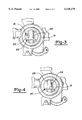
- FIG. 3 is a view similar to FIG. 4 illustrating the fragmented top view of a clevis joint in its clamped position.
- FIG. 4 is a top view of a portion of the suspension of FIGS. 1A and 1 illustrating a clevis joint in an unclamped position.
- FIG. 5 is an enlarged fragmented view of the apparatus for shock absorber removal of FIG. 2 shown removed from the front suspension for purposes of illustration.
- FIG. 6 is a side view of the apparatus for shock absorber removal of FIG. 5.
- FIG. 7 is an exploded view of an alternate embodiment of the apparatus for shock absorber removal.
- a portion of a front suspension 10 is shown to generally include a shock absorber 12 vertically enclosed within a coil spring 18.
- the suspension 10 further includes an upper suspension arm 22 and lower suspension arm 24 horizontally disposed away from the shock absorber 12.
- Shock absorber 12 has a first end portion 14 and second end portion 16 and is normally clamped within a clevis bracket 20 (shown most clearly in FIGS. 3 and 4) at second end 16.
- Clevis bracket 20 includes two legs, 26 and 28, and is mounted within a coil spring base 19.
- a fastener such as a lower shock bolt 29, functions to retain second end 16 in a fixed mounting position.
- lower shock bolt 29 inelastically deforms leg 26 of clevis joint 20 (see FIG. 4).
- FIG. 3 depicts second end 16 trapped between inelastically deformed leg 26 of clevis joint 20 and coil spring base 19.
- FIG. 4 depicts leg 26 of clevis joint 20 returned to its original shape to allow removal of second end 16.
- first end 14 of the shock absorber 12 is enclosed by upper shock bracket 30 and connected to an engine compartment (not shown) of a vehicle by grommet 32 and retainer 34.
- Shock bracket 30 is mounted to the coil spring 18 by bolts 36 located on a circular top 35 of the coil spring 18.
- head 50 is integrally connected to first end 46 of first portion 44 to form a single body.
- Second portion 50 may be welded to first portion 44 or stamped in a forge to produce an integral unit.
- Head 50 may be any material capable of receiving a driving force, such as iron.
- Head 50 preferably has flat sides 54 which upwardly taper to a rounded edge 56. In side view, the head 50 is shown to include a pair of rounded sides 58.
- substantially flat edge 56 is preferably approximately 0.70 inches and head 50 is 1.91 inches in width.
- the length of head 50 is about 2.0 inches and flat sides 54 are about 4.0 inches in length.
- first portion 44 is approximately 27 inches in length and 1.0 inches in diameter.
- the apparatus 38 must be strong enough to wedge between and spread the legs 26 and 28 of clevis bracket 20 to facilitate removal of the shock absorber 12, but small enough to avoid damaging the bracket 19. In order to accomplish this, for an embodiment where the shock absorber 12 is about 27 inches in length and 23/8 inches in width, apparatus 38 is approximately 31 inches in length.
- FIG. 7 An alternate embodiment of the apparatus 38' of the present invention is shown depicted in FIG. 7.
- the embodiment depicts a first portion 58 and second portion 60 removably engageable with the first portion 58.
- First portion 58 has threaded means 62 for mating with second portion 60, while second portion 60 has receiving means 64.
- the apparatus 38' may further include a plurality of interchangeable second portions 60, ranging in size and diameter, in order to be able to employ the apparatus 38' to remove different sized shocks 12.
Abstract
Description
Claims (13)
Priority Applications (1)
| Application Number | Priority Date | Filing Date | Title |
|---|---|---|---|
| US09/083,990 US6145179A (en) | 1998-05-22 | 1998-05-22 | Method and apparatus for shock absorber removal |
Applications Claiming Priority (1)
| Application Number | Priority Date | Filing Date | Title |
|---|---|---|---|
| US09/083,990 US6145179A (en) | 1998-05-22 | 1998-05-22 | Method and apparatus for shock absorber removal |
Publications (1)
| Publication Number | Publication Date |
|---|---|
| US6145179A true US6145179A (en) | 2000-11-14 |
Family
ID=22181938
Family Applications (1)
| Application Number | Title | Priority Date | Filing Date |
|---|---|---|---|
| US09/083,990 Expired - Lifetime US6145179A (en) | 1998-05-22 | 1998-05-22 | Method and apparatus for shock absorber removal |
Country Status (1)
| Country | Link |
|---|---|
| US (1) | US6145179A (en) |
Cited By (1)
| Publication number | Priority date | Publication date | Assignee | Title |
|---|---|---|---|---|
| US20080168641A1 (en) * | 2007-01-15 | 2008-07-17 | Honda Motor Co., Ltd. | Suspension damper removal tool |
Citations (16)
| Publication number | Priority date | Publication date | Assignee | Title |
|---|---|---|---|---|
| US1400676A (en) * | 1920-12-02 | 1921-12-20 | Perry G Gully | Bushing-remover |
| US1784033A (en) * | 1928-07-12 | 1930-12-09 | George E Swanby | Automobile tool |
| US2523041A (en) * | 1948-03-03 | 1950-09-19 | Hugh H Mckenzie | Screw driver |
| US3191909A (en) * | 1963-03-29 | 1965-06-29 | Norbert M Reischl | Spot weld separator |
| US3916734A (en) * | 1974-08-21 | 1975-11-04 | Anis S Sawan | Tool for use in removing automobile shock absorbers |
| US3935760A (en) * | 1974-01-31 | 1976-02-03 | Taylor Bobby W | Tool for removing shock absorbers and the like |
| US4073046A (en) * | 1975-10-28 | 1978-02-14 | Ramsden Frederick G | Shock absorber installation tool |
| US4346518A (en) * | 1980-11-21 | 1982-08-31 | Wood David A | Shock absorber removing tool |
| US4522090A (en) * | 1983-05-02 | 1985-06-11 | Donald Kittle | Combination vehicle, shock absorber and tool to remove said shock absorbers from said vehicle |
| US4571809A (en) * | 1984-05-10 | 1986-02-25 | Rossow Robert O | Shock absorber tool |
| US4576066A (en) * | 1981-03-10 | 1986-03-18 | Kloster Kenneth D | Tool for removing fasteners from shock absorber cylinders |
| US4620360A (en) * | 1984-12-24 | 1986-11-04 | Lisle Corporation | Shock absorber removing tool |
| US4813118A (en) * | 1984-01-18 | 1989-03-21 | Bernhard Schmack | Tool system for changing shock absorber cartridges |
| US5390572A (en) * | 1993-07-27 | 1995-02-21 | Vermont American Corporation | Tool with immproved impact and torque capabilities and having ergonomic handle |
| US5455996A (en) * | 1992-12-28 | 1995-10-10 | Lisle Corporation | Brake spring tool |
| US5816606A (en) * | 1995-10-05 | 1998-10-06 | Chrysler Corporation | Horizontally-mounted rear shock absorber for lightweight motor vehicle |
-
1998
- 1998-05-22 US US09/083,990 patent/US6145179A/en not_active Expired - Lifetime
Patent Citations (16)
| Publication number | Priority date | Publication date | Assignee | Title |
|---|---|---|---|---|
| US1400676A (en) * | 1920-12-02 | 1921-12-20 | Perry G Gully | Bushing-remover |
| US1784033A (en) * | 1928-07-12 | 1930-12-09 | George E Swanby | Automobile tool |
| US2523041A (en) * | 1948-03-03 | 1950-09-19 | Hugh H Mckenzie | Screw driver |
| US3191909A (en) * | 1963-03-29 | 1965-06-29 | Norbert M Reischl | Spot weld separator |
| US3935760A (en) * | 1974-01-31 | 1976-02-03 | Taylor Bobby W | Tool for removing shock absorbers and the like |
| US3916734A (en) * | 1974-08-21 | 1975-11-04 | Anis S Sawan | Tool for use in removing automobile shock absorbers |
| US4073046A (en) * | 1975-10-28 | 1978-02-14 | Ramsden Frederick G | Shock absorber installation tool |
| US4346518A (en) * | 1980-11-21 | 1982-08-31 | Wood David A | Shock absorber removing tool |
| US4576066A (en) * | 1981-03-10 | 1986-03-18 | Kloster Kenneth D | Tool for removing fasteners from shock absorber cylinders |
| US4522090A (en) * | 1983-05-02 | 1985-06-11 | Donald Kittle | Combination vehicle, shock absorber and tool to remove said shock absorbers from said vehicle |
| US4813118A (en) * | 1984-01-18 | 1989-03-21 | Bernhard Schmack | Tool system for changing shock absorber cartridges |
| US4571809A (en) * | 1984-05-10 | 1986-02-25 | Rossow Robert O | Shock absorber tool |
| US4620360A (en) * | 1984-12-24 | 1986-11-04 | Lisle Corporation | Shock absorber removing tool |
| US5455996A (en) * | 1992-12-28 | 1995-10-10 | Lisle Corporation | Brake spring tool |
| US5390572A (en) * | 1993-07-27 | 1995-02-21 | Vermont American Corporation | Tool with immproved impact and torque capabilities and having ergonomic handle |
| US5816606A (en) * | 1995-10-05 | 1998-10-06 | Chrysler Corporation | Horizontally-mounted rear shock absorber for lightweight motor vehicle |
Cited By (2)
| Publication number | Priority date | Publication date | Assignee | Title |
|---|---|---|---|---|
| US20080168641A1 (en) * | 2007-01-15 | 2008-07-17 | Honda Motor Co., Ltd. | Suspension damper removal tool |
| US7992277B2 (en) | 2007-01-15 | 2011-08-09 | Honda Motor Co., Ltd. | Suspension damper removal tool |
Similar Documents
| Publication | Publication Date | Title |
|---|---|---|
| US5967553A (en) | Bracket for mud flaps and snowplow diverters | |
| US3030837A (en) | Dent-removing hand tool | |
| US8689420B2 (en) | Apparatus and method for installing and removing wheel studs | |
| CA2285139C (en) | Mud flap holder apparatus | |
| US5638909A (en) | Bolt removal device and method for an air hammer | |
| US6145179A (en) | Method and apparatus for shock absorber removal | |
| US4073046A (en) | Shock absorber installation tool | |
| US4827759A (en) | Dent pulling apparatus | |
| EP1413375A3 (en) | Clamping device for tool holder | |
| US5335533A (en) | Pull clamps for straightening automobile underframes and door hinge pillars, and their use | |
| US4959991A (en) | Vehicle chassis support | |
| US20090025514A1 (en) | Wheel stud installing and removing system and method | |
| US5443564A (en) | Tie rod loosening tool for use with a tie rod assembly | |
| US4309894A (en) | Auto body repair tool | |
| EP0253269A2 (en) | Fixing clamp for straightening the bodywork of accident-damaged automobiles, and in particular the sheet metal seats for Macpherson suspension heads | |
| KR100191615B1 (en) | Nut fixture apparatus | |
| US4188722A (en) | Cutting tool for removing a nut securely fastened to a bolt | |
| US5156037A (en) | Clamping apparatus for repairing an automobile chassis | |
| KR0134071Y1 (en) | Sheet metal working jig of an automobile | |
| KR20020080711A (en) | Tool for stripping outer race of hub bearing | |
| US7434444B2 (en) | Frame rail pulling apparatus | |
| US6131883A (en) | Strut removal tool | |
| KR100507002B1 (en) | Support member for removing a torque rod for a vehicle and device having the same | |
| KR200161999Y1 (en) | Ball joint removable tool | |
| JP3218777U (en) | Spanner tilt holder |
Legal Events
| Date | Code | Title | Description |
|---|---|---|---|
| AS | Assignment |
Owner name: CHRYSLER CORPORATION, MICHIGAN Free format text: ASSIGNMENT OF ASSIGNORS INTEREST;ASSIGNORS:SMITH, RICHARD A.;MAULDIN, DARREN;REEL/FRAME:009278/0269 Effective date: 19980505 |
|
| STCF | Information on status: patent grant |
Free format text: PATENTED CASE |
|
| FPAY | Fee payment |
Year of fee payment: 4 |
|
| AS | Assignment |
Owner name: WILMINGTON TRUST COMPANY, DELAWARE Free format text: GRANT OF SECURITY INTEREST IN PATENT RIGHTS - FIRST PRIORITY;ASSIGNOR:CHRYSLER LLC;REEL/FRAME:019773/0001 Effective date: 20070803 Owner name: WILMINGTON TRUST COMPANY,DELAWARE Free format text: GRANT OF SECURITY INTEREST IN PATENT RIGHTS - FIRST PRIORITY;ASSIGNOR:CHRYSLER LLC;REEL/FRAME:019773/0001 Effective date: 20070803 |
|
| AS | Assignment |
Owner name: WILMINGTON TRUST COMPANY, DELAWARE Free format text: GRANT OF SECURITY INTEREST IN PATENT RIGHTS - SECOND PRIORITY;ASSIGNOR:CHRYSLER LLC;REEL/FRAME:019767/0810 Effective date: 20070803 Owner name: WILMINGTON TRUST COMPANY,DELAWARE Free format text: GRANT OF SECURITY INTEREST IN PATENT RIGHTS - SECOND PRIORITY;ASSIGNOR:CHRYSLER LLC;REEL/FRAME:019767/0810 Effective date: 20070803 |
|
| FPAY | Fee payment |
Year of fee payment: 8 |
|
| AS | Assignment |
Owner name: DAIMLERCHRYSLER CORPORATION, MICHIGAN Free format text: CHANGE OF NAME;ASSIGNOR:CHRYSLER CORPORATION;REEL/FRAME:021826/0034 Effective date: 19981116 |
|
| AS | Assignment |
Owner name: CHRYSLER LLC, MICHIGAN Free format text: CHANGE OF NAME;ASSIGNOR:DAIMLERCHRYSLER COMPANY LLC;REEL/FRAME:021832/0233 Effective date: 20070727 Owner name: DAIMLERCHRYSLER COMPANY LLC, MICHIGAN Free format text: CHANGE OF NAME;ASSIGNOR:DAIMLERCHRYSLER CORPORATION;REEL/FRAME:021832/0256 Effective date: 20070329 |
|
| AS | Assignment |
Owner name: US DEPARTMENT OF THE TREASURY, DISTRICT OF COLUMBI Free format text: GRANT OF SECURITY INTEREST IN PATENT RIGHTS - THIR;ASSIGNOR:CHRYSLER LLC;REEL/FRAME:022259/0188 Effective date: 20090102 Owner name: US DEPARTMENT OF THE TREASURY,DISTRICT OF COLUMBIA Free format text: GRANT OF SECURITY INTEREST IN PATENT RIGHTS - THIR;ASSIGNOR:CHRYSLER LLC;REEL/FRAME:022259/0188 Effective date: 20090102 |
|
| AS | Assignment |
Owner name: CHRYSLER LLC, MICHIGAN Free format text: RELEASE BY SECURED PARTY;ASSIGNOR:US DEPARTMENT OF THE TREASURY;REEL/FRAME:022910/0273 Effective date: 20090608 |
|
| AS | Assignment |
Owner name: CHRYSLER LLC, MICHIGAN Free format text: RELEASE OF SECURITY INTEREST IN PATENT RIGHTS - FIRST PRIORITY;ASSIGNOR:WILMINGTON TRUST COMPANY;REEL/FRAME:022910/0498 Effective date: 20090604 Owner name: CHRYSLER LLC, MICHIGAN Free format text: RELEASE OF SECURITY INTEREST IN PATENT RIGHTS - SECOND PRIORITY;ASSIGNOR:WILMINGTON TRUST COMPANY;REEL/FRAME:022910/0740 Effective date: 20090604 Owner name: NEW CARCO ACQUISITION LLC, MICHIGAN Free format text: ASSIGNMENT OF ASSIGNORS INTEREST;ASSIGNOR:CHRYSLER LLC;REEL/FRAME:022915/0001 Effective date: 20090610 Owner name: THE UNITED STATES DEPARTMENT OF THE TREASURY, DIST Free format text: SECURITY AGREEMENT;ASSIGNOR:NEW CARCO ACQUISITION LLC;REEL/FRAME:022915/0489 Effective date: 20090610 Owner name: CHRYSLER LLC,MICHIGAN Free format text: RELEASE OF SECURITY INTEREST IN PATENT RIGHTS - FIRST PRIORITY;ASSIGNOR:WILMINGTON TRUST COMPANY;REEL/FRAME:022910/0498 Effective date: 20090604 Owner name: CHRYSLER LLC,MICHIGAN Free format text: RELEASE OF SECURITY INTEREST IN PATENT RIGHTS - SECOND PRIORITY;ASSIGNOR:WILMINGTON TRUST COMPANY;REEL/FRAME:022910/0740 Effective date: 20090604 Owner name: NEW CARCO ACQUISITION LLC,MICHIGAN Free format text: ASSIGNMENT OF ASSIGNORS INTEREST;ASSIGNOR:CHRYSLER LLC;REEL/FRAME:022915/0001 Effective date: 20090610 Owner name: THE UNITED STATES DEPARTMENT OF THE TREASURY,DISTR Free format text: SECURITY AGREEMENT;ASSIGNOR:NEW CARCO ACQUISITION LLC;REEL/FRAME:022915/0489 Effective date: 20090610 |
|
| AS | Assignment |
Owner name: CHRYSLER GROUP LLC, MICHIGAN Free format text: CHANGE OF NAME;ASSIGNOR:NEW CARCO ACQUISITION LLC;REEL/FRAME:022919/0126 Effective date: 20090610 Owner name: CHRYSLER GROUP LLC,MICHIGAN Free format text: CHANGE OF NAME;ASSIGNOR:NEW CARCO ACQUISITION LLC;REEL/FRAME:022919/0126 Effective date: 20090610 |
|
| AS | Assignment |
Owner name: CHRYSLER GROUP GLOBAL ELECTRIC MOTORCARS LLC, NORT Free format text: RELEASE BY SECURED PARTY;ASSIGNOR:THE UNITED STATES DEPARTMENT OF THE TREASURY;REEL/FRAME:026343/0298 Effective date: 20110524 Owner name: CHRYSLER GROUP LLC, MICHIGAN Free format text: RELEASE BY SECURED PARTY;ASSIGNOR:THE UNITED STATES DEPARTMENT OF THE TREASURY;REEL/FRAME:026343/0298 Effective date: 20110524 |
|
| AS | Assignment |
Owner name: CITIBANK, N.A., NEW YORK Free format text: SECURITY AGREEMENT;ASSIGNOR:CHRYSLER GROUP LLC;REEL/FRAME:026404/0123 Effective date: 20110524 |
|
| AS | Assignment |
Owner name: CITIBANK, N.A., NEW YORK Free format text: SECURITY AGREEMENT;ASSIGNOR:CHRYSLER GROUP LLC;REEL/FRAME:026435/0652 Effective date: 20110524 |
|
| FPAY | Fee payment |
Year of fee payment: 12 |
|
| AS | Assignment |
Owner name: JPMORGAN CHASE BANK, N.A., ILLINOIS Free format text: SECURITY AGREEMENT;ASSIGNOR:CHRYSLER GROUP LLC;REEL/FRAME:032384/0640 Effective date: 20140207 |
|
| AS | Assignment |
Owner name: FCA US LLC, MICHIGAN Free format text: CHANGE OF NAME;ASSIGNOR:CHRYSLER GROUP LLC;REEL/FRAME:035553/0356 Effective date: 20141203 |
|
| AS | Assignment |
Owner name: FCA US LLC, FORMERLY KNOWN AS CHRYSLER GROUP LLC, Free format text: RELEASE OF SECURITY INTEREST RELEASING SECOND-LIEN SECURITY INTEREST PREVIOUSLY RECORDED AT REEL 026426 AND FRAME 0644, REEL 026435 AND FRAME 0652, AND REEL 032384 AND FRAME 0591;ASSIGNOR:CITIBANK, N.A.;REEL/FRAME:037784/0001 Effective date: 20151221 |
|
| AS | Assignment |
Owner name: FCA US LLC (FORMERLY KNOWN AS CHRYSLER GROUP LLC), Free format text: RELEASE BY SECURED PARTY;ASSIGNOR:CITIBANK, N.A.;REEL/FRAME:042885/0255 Effective date: 20170224 |
|
| AS | Assignment |
Owner name: FCA US LLC (FORMERLY KNOWN AS CHRYSLER GROUP LLC), Free format text: RELEASE BY SECURED PARTY;ASSIGNOR:JPMORGAN CHASE BANK, N.A.;REEL/FRAME:048177/0356 Effective date: 20181113 |