US6142329A - Knock-down bin - Google Patents
Knock-down bin Download PDFInfo
- Publication number
- US6142329A US6142329A US09/494,042 US49404200A US6142329A US 6142329 A US6142329 A US 6142329A US 49404200 A US49404200 A US 49404200A US 6142329 A US6142329 A US 6142329A
- Authority
- US
- United States
- Prior art keywords
- sides
- locking element
- bin
- projection
- corner
- Prior art date
- Legal status (The legal status is an assumption and is not a legal conclusion. Google has not performed a legal analysis and makes no representation as to the accuracy of the status listed.)
- Expired - Lifetime
Links
- 238000003197 gene knockdown Methods 0.000 title claims abstract description 15
- 239000002861 polymer material Substances 0.000 claims abstract description 6
- 229920000642 polymer Polymers 0.000 description 2
- 238000009877 rendering Methods 0.000 description 2
- 230000000717 retained effect Effects 0.000 description 2
- 230000000712 assembly Effects 0.000 description 1
- 238000000429 assembly Methods 0.000 description 1
- 230000000694 effects Effects 0.000 description 1
- 238000003780 insertion Methods 0.000 description 1
- 230000037431 insertion Effects 0.000 description 1
- 239000002184 metal Substances 0.000 description 1
- 238000000034 method Methods 0.000 description 1
- 238000012856 packing Methods 0.000 description 1
- 239000002994 raw material Substances 0.000 description 1
- 230000003014 reinforcing effect Effects 0.000 description 1
- 239000007787 solid Substances 0.000 description 1
Images


Classifications
-
- B—PERFORMING OPERATIONS; TRANSPORTING
- B65—CONVEYING; PACKING; STORING; HANDLING THIN OR FILAMENTARY MATERIAL
- B65D—CONTAINERS FOR STORAGE OR TRANSPORT OF ARTICLES OR MATERIALS, e.g. BAGS, BARRELS, BOTTLES, BOXES, CANS, CARTONS, CRATES, DRUMS, JARS, TANKS, HOPPERS, FORWARDING CONTAINERS; ACCESSORIES, CLOSURES, OR FITTINGS THEREFOR; PACKAGING ELEMENTS; PACKAGES
- B65D19/00—Pallets or like platforms, with or without side walls, for supporting loads to be lifted or lowered
- B65D19/02—Rigid pallets with side walls, e.g. box pallets
- B65D19/06—Rigid pallets with side walls, e.g. box pallets with bodies formed by uniting or interconnecting two or more components
- B65D19/18—Rigid pallets with side walls, e.g. box pallets with bodies formed by uniting or interconnecting two or more components made wholly or mainly of plastics material
-
- B—PERFORMING OPERATIONS; TRANSPORTING
- B65—CONVEYING; PACKING; STORING; HANDLING THIN OR FILAMENTARY MATERIAL
- B65D—CONTAINERS FOR STORAGE OR TRANSPORT OF ARTICLES OR MATERIALS, e.g. BAGS, BARRELS, BOTTLES, BOXES, CANS, CARTONS, CRATES, DRUMS, JARS, TANKS, HOPPERS, FORWARDING CONTAINERS; ACCESSORIES, CLOSURES, OR FITTINGS THEREFOR; PACKAGING ELEMENTS; PACKAGES
- B65D2519/00—Pallets or like platforms, with or without side walls, for supporting loads to be lifted or lowered
- B65D2519/00004—Details relating to pallets
- B65D2519/00009—Materials
- B65D2519/00014—Materials for the load supporting surface
- B65D2519/00034—Plastic
-
- B—PERFORMING OPERATIONS; TRANSPORTING
- B65—CONVEYING; PACKING; STORING; HANDLING THIN OR FILAMENTARY MATERIAL
- B65D—CONTAINERS FOR STORAGE OR TRANSPORT OF ARTICLES OR MATERIALS, e.g. BAGS, BARRELS, BOTTLES, BOXES, CANS, CARTONS, CRATES, DRUMS, JARS, TANKS, HOPPERS, FORWARDING CONTAINERS; ACCESSORIES, CLOSURES, OR FITTINGS THEREFOR; PACKAGING ELEMENTS; PACKAGES
- B65D2519/00—Pallets or like platforms, with or without side walls, for supporting loads to be lifted or lowered
- B65D2519/00004—Details relating to pallets
- B65D2519/00009—Materials
- B65D2519/00049—Materials for the base surface
- B65D2519/00069—Plastic
-
- B—PERFORMING OPERATIONS; TRANSPORTING
- B65—CONVEYING; PACKING; STORING; HANDLING THIN OR FILAMENTARY MATERIAL
- B65D—CONTAINERS FOR STORAGE OR TRANSPORT OF ARTICLES OR MATERIALS, e.g. BAGS, BARRELS, BOTTLES, BOXES, CANS, CARTONS, CRATES, DRUMS, JARS, TANKS, HOPPERS, FORWARDING CONTAINERS; ACCESSORIES, CLOSURES, OR FITTINGS THEREFOR; PACKAGING ELEMENTS; PACKAGES
- B65D2519/00—Pallets or like platforms, with or without side walls, for supporting loads to be lifted or lowered
- B65D2519/00004—Details relating to pallets
- B65D2519/00009—Materials
- B65D2519/00119—Materials for the construction of the reinforcements
- B65D2519/00139—Plastic
-
- B—PERFORMING OPERATIONS; TRANSPORTING
- B65—CONVEYING; PACKING; STORING; HANDLING THIN OR FILAMENTARY MATERIAL
- B65D—CONTAINERS FOR STORAGE OR TRANSPORT OF ARTICLES OR MATERIALS, e.g. BAGS, BARRELS, BOTTLES, BOXES, CANS, CARTONS, CRATES, DRUMS, JARS, TANKS, HOPPERS, FORWARDING CONTAINERS; ACCESSORIES, CLOSURES, OR FITTINGS THEREFOR; PACKAGING ELEMENTS; PACKAGES
- B65D2519/00—Pallets or like platforms, with or without side walls, for supporting loads to be lifted or lowered
- B65D2519/00004—Details relating to pallets
- B65D2519/00009—Materials
- B65D2519/00154—Materials for the side walls
- B65D2519/00174—Plastic
-
- B—PERFORMING OPERATIONS; TRANSPORTING
- B65—CONVEYING; PACKING; STORING; HANDLING THIN OR FILAMENTARY MATERIAL
- B65D—CONTAINERS FOR STORAGE OR TRANSPORT OF ARTICLES OR MATERIALS, e.g. BAGS, BARRELS, BOTTLES, BOXES, CANS, CARTONS, CRATES, DRUMS, JARS, TANKS, HOPPERS, FORWARDING CONTAINERS; ACCESSORIES, CLOSURES, OR FITTINGS THEREFOR; PACKAGING ELEMENTS; PACKAGES
- B65D2519/00—Pallets or like platforms, with or without side walls, for supporting loads to be lifted or lowered
- B65D2519/00004—Details relating to pallets
- B65D2519/00009—Materials
- B65D2519/00223—Materials for the corner elements or corner frames
- B65D2519/00243—Plastic
-
- B—PERFORMING OPERATIONS; TRANSPORTING
- B65—CONVEYING; PACKING; STORING; HANDLING THIN OR FILAMENTARY MATERIAL
- B65D—CONTAINERS FOR STORAGE OR TRANSPORT OF ARTICLES OR MATERIALS, e.g. BAGS, BARRELS, BOTTLES, BOXES, CANS, CARTONS, CRATES, DRUMS, JARS, TANKS, HOPPERS, FORWARDING CONTAINERS; ACCESSORIES, CLOSURES, OR FITTINGS THEREFOR; PACKAGING ELEMENTS; PACKAGES
- B65D2519/00—Pallets or like platforms, with or without side walls, for supporting loads to be lifted or lowered
- B65D2519/00004—Details relating to pallets
- B65D2519/00258—Overall construction
- B65D2519/00263—Overall construction of the pallet
- B65D2519/00268—Overall construction of the pallet made of one piece
-
- B—PERFORMING OPERATIONS; TRANSPORTING
- B65—CONVEYING; PACKING; STORING; HANDLING THIN OR FILAMENTARY MATERIAL
- B65D—CONTAINERS FOR STORAGE OR TRANSPORT OF ARTICLES OR MATERIALS, e.g. BAGS, BARRELS, BOTTLES, BOXES, CANS, CARTONS, CRATES, DRUMS, JARS, TANKS, HOPPERS, FORWARDING CONTAINERS; ACCESSORIES, CLOSURES, OR FITTINGS THEREFOR; PACKAGING ELEMENTS; PACKAGES
- B65D2519/00—Pallets or like platforms, with or without side walls, for supporting loads to be lifted or lowered
- B65D2519/00004—Details relating to pallets
- B65D2519/00258—Overall construction
- B65D2519/00283—Overall construction of the load supporting surface
- B65D2519/00288—Overall construction of the load supporting surface made of one piece
-
- B—PERFORMING OPERATIONS; TRANSPORTING
- B65—CONVEYING; PACKING; STORING; HANDLING THIN OR FILAMENTARY MATERIAL
- B65D—CONTAINERS FOR STORAGE OR TRANSPORT OF ARTICLES OR MATERIALS, e.g. BAGS, BARRELS, BOTTLES, BOXES, CANS, CARTONS, CRATES, DRUMS, JARS, TANKS, HOPPERS, FORWARDING CONTAINERS; ACCESSORIES, CLOSURES, OR FITTINGS THEREFOR; PACKAGING ELEMENTS; PACKAGES
- B65D2519/00—Pallets or like platforms, with or without side walls, for supporting loads to be lifted or lowered
- B65D2519/00004—Details relating to pallets
- B65D2519/00258—Overall construction
- B65D2519/00283—Overall construction of the load supporting surface
- B65D2519/00308—Overall construction of the load supporting surface grid type, e.g. perforated plate
-
- B—PERFORMING OPERATIONS; TRANSPORTING
- B65—CONVEYING; PACKING; STORING; HANDLING THIN OR FILAMENTARY MATERIAL
- B65D—CONTAINERS FOR STORAGE OR TRANSPORT OF ARTICLES OR MATERIALS, e.g. BAGS, BARRELS, BOTTLES, BOXES, CANS, CARTONS, CRATES, DRUMS, JARS, TANKS, HOPPERS, FORWARDING CONTAINERS; ACCESSORIES, CLOSURES, OR FITTINGS THEREFOR; PACKAGING ELEMENTS; PACKAGES
- B65D2519/00—Pallets or like platforms, with or without side walls, for supporting loads to be lifted or lowered
- B65D2519/00004—Details relating to pallets
- B65D2519/00258—Overall construction
- B65D2519/00313—Overall construction of the base surface
- B65D2519/00318—Overall construction of the base surface made of one piece
-
- B—PERFORMING OPERATIONS; TRANSPORTING
- B65—CONVEYING; PACKING; STORING; HANDLING THIN OR FILAMENTARY MATERIAL
- B65D—CONTAINERS FOR STORAGE OR TRANSPORT OF ARTICLES OR MATERIALS, e.g. BAGS, BARRELS, BOTTLES, BOXES, CANS, CARTONS, CRATES, DRUMS, JARS, TANKS, HOPPERS, FORWARDING CONTAINERS; ACCESSORIES, CLOSURES, OR FITTINGS THEREFOR; PACKAGING ELEMENTS; PACKAGES
- B65D2519/00—Pallets or like platforms, with or without side walls, for supporting loads to be lifted or lowered
- B65D2519/00004—Details relating to pallets
- B65D2519/00258—Overall construction
- B65D2519/00313—Overall construction of the base surface
- B65D2519/00328—Overall construction of the base surface shape of the contact surface of the base
- B65D2519/00333—Overall construction of the base surface shape of the contact surface of the base contact surface having a stringer-like shape
-
- B—PERFORMING OPERATIONS; TRANSPORTING
- B65—CONVEYING; PACKING; STORING; HANDLING THIN OR FILAMENTARY MATERIAL
- B65D—CONTAINERS FOR STORAGE OR TRANSPORT OF ARTICLES OR MATERIALS, e.g. BAGS, BARRELS, BOTTLES, BOXES, CANS, CARTONS, CRATES, DRUMS, JARS, TANKS, HOPPERS, FORWARDING CONTAINERS; ACCESSORIES, CLOSURES, OR FITTINGS THEREFOR; PACKAGING ELEMENTS; PACKAGES
- B65D2519/00—Pallets or like platforms, with or without side walls, for supporting loads to be lifted or lowered
- B65D2519/00004—Details relating to pallets
- B65D2519/00258—Overall construction
- B65D2519/00398—Overall construction reinforcements
- B65D2519/00402—Integral, e.g. ribs
- B65D2519/00412—Integral, e.g. ribs on the base surface
-
- B—PERFORMING OPERATIONS; TRANSPORTING
- B65—CONVEYING; PACKING; STORING; HANDLING THIN OR FILAMENTARY MATERIAL
- B65D—CONTAINERS FOR STORAGE OR TRANSPORT OF ARTICLES OR MATERIALS, e.g. BAGS, BARRELS, BOTTLES, BOXES, CANS, CARTONS, CRATES, DRUMS, JARS, TANKS, HOPPERS, FORWARDING CONTAINERS; ACCESSORIES, CLOSURES, OR FITTINGS THEREFOR; PACKAGING ELEMENTS; PACKAGES
- B65D2519/00—Pallets or like platforms, with or without side walls, for supporting loads to be lifted or lowered
- B65D2519/00004—Details relating to pallets
- B65D2519/00258—Overall construction
- B65D2519/00398—Overall construction reinforcements
- B65D2519/00402—Integral, e.g. ribs
- B65D2519/00422—Integral, e.g. ribs on the walls
-
- B—PERFORMING OPERATIONS; TRANSPORTING
- B65—CONVEYING; PACKING; STORING; HANDLING THIN OR FILAMENTARY MATERIAL
- B65D—CONTAINERS FOR STORAGE OR TRANSPORT OF ARTICLES OR MATERIALS, e.g. BAGS, BARRELS, BOTTLES, BOXES, CANS, CARTONS, CRATES, DRUMS, JARS, TANKS, HOPPERS, FORWARDING CONTAINERS; ACCESSORIES, CLOSURES, OR FITTINGS THEREFOR; PACKAGING ELEMENTS; PACKAGES
- B65D2519/00—Pallets or like platforms, with or without side walls, for supporting loads to be lifted or lowered
- B65D2519/00004—Details relating to pallets
- B65D2519/00258—Overall construction
- B65D2519/00398—Overall construction reinforcements
- B65D2519/00432—Non-integral, e.g. inserts
- B65D2519/00452—Non-integral, e.g. inserts on the walls
-
- B—PERFORMING OPERATIONS; TRANSPORTING
- B65—CONVEYING; PACKING; STORING; HANDLING THIN OR FILAMENTARY MATERIAL
- B65D—CONTAINERS FOR STORAGE OR TRANSPORT OF ARTICLES OR MATERIALS, e.g. BAGS, BARRELS, BOTTLES, BOXES, CANS, CARTONS, CRATES, DRUMS, JARS, TANKS, HOPPERS, FORWARDING CONTAINERS; ACCESSORIES, CLOSURES, OR FITTINGS THEREFOR; PACKAGING ELEMENTS; PACKAGES
- B65D2519/00—Pallets or like platforms, with or without side walls, for supporting loads to be lifted or lowered
- B65D2519/00004—Details relating to pallets
- B65D2519/00258—Overall construction
- B65D2519/00492—Overall construction of the side walls
- B65D2519/00497—Overall construction of the side walls whereby at least one side wall is made of one piece
-
- B—PERFORMING OPERATIONS; TRANSPORTING
- B65—CONVEYING; PACKING; STORING; HANDLING THIN OR FILAMENTARY MATERIAL
- B65D—CONTAINERS FOR STORAGE OR TRANSPORT OF ARTICLES OR MATERIALS, e.g. BAGS, BARRELS, BOTTLES, BOXES, CANS, CARTONS, CRATES, DRUMS, JARS, TANKS, HOPPERS, FORWARDING CONTAINERS; ACCESSORIES, CLOSURES, OR FITTINGS THEREFOR; PACKAGING ELEMENTS; PACKAGES
- B65D2519/00—Pallets or like platforms, with or without side walls, for supporting loads to be lifted or lowered
- B65D2519/00004—Details relating to pallets
- B65D2519/00258—Overall construction
- B65D2519/00492—Overall construction of the side walls
- B65D2519/00502—Overall construction of the side walls whereby at least one side wall is made of two or more pieces
-
- B—PERFORMING OPERATIONS; TRANSPORTING
- B65—CONVEYING; PACKING; STORING; HANDLING THIN OR FILAMENTARY MATERIAL
- B65D—CONTAINERS FOR STORAGE OR TRANSPORT OF ARTICLES OR MATERIALS, e.g. BAGS, BARRELS, BOTTLES, BOXES, CANS, CARTONS, CRATES, DRUMS, JARS, TANKS, HOPPERS, FORWARDING CONTAINERS; ACCESSORIES, CLOSURES, OR FITTINGS THEREFOR; PACKAGING ELEMENTS; PACKAGES
- B65D2519/00—Pallets or like platforms, with or without side walls, for supporting loads to be lifted or lowered
- B65D2519/00004—Details relating to pallets
- B65D2519/00258—Overall construction
- B65D2519/00492—Overall construction of the side walls
- B65D2519/00522—Overall construction of the side walls grid type, e.g. perforated plate
-
- B—PERFORMING OPERATIONS; TRANSPORTING
- B65—CONVEYING; PACKING; STORING; HANDLING THIN OR FILAMENTARY MATERIAL
- B65D—CONTAINERS FOR STORAGE OR TRANSPORT OF ARTICLES OR MATERIALS, e.g. BAGS, BARRELS, BOTTLES, BOXES, CANS, CARTONS, CRATES, DRUMS, JARS, TANKS, HOPPERS, FORWARDING CONTAINERS; ACCESSORIES, CLOSURES, OR FITTINGS THEREFOR; PACKAGING ELEMENTS; PACKAGES
- B65D2519/00—Pallets or like platforms, with or without side walls, for supporting loads to be lifted or lowered
- B65D2519/00004—Details relating to pallets
- B65D2519/00547—Connections
- B65D2519/00552—Structures connecting the constitutive elements of the pallet to each other, i.e. load supporting surface, base surface and/or separate spacer
- B65D2519/00557—Structures connecting the constitutive elements of the pallet to each other, i.e. load supporting surface, base surface and/or separate spacer without separate auxiliary elements
-
- B—PERFORMING OPERATIONS; TRANSPORTING
- B65—CONVEYING; PACKING; STORING; HANDLING THIN OR FILAMENTARY MATERIAL
- B65D—CONTAINERS FOR STORAGE OR TRANSPORT OF ARTICLES OR MATERIALS, e.g. BAGS, BARRELS, BOTTLES, BOXES, CANS, CARTONS, CRATES, DRUMS, JARS, TANKS, HOPPERS, FORWARDING CONTAINERS; ACCESSORIES, CLOSURES, OR FITTINGS THEREFOR; PACKAGING ELEMENTS; PACKAGES
- B65D2519/00—Pallets or like platforms, with or without side walls, for supporting loads to be lifted or lowered
- B65D2519/00004—Details relating to pallets
- B65D2519/00547—Connections
- B65D2519/00577—Connections structures connecting side walls, including corner posts, to each other
- B65D2519/00582—Connections structures connecting side walls, including corner posts, to each other structures intended to be disassembled, i.e. collapsible or dismountable
- B65D2519/00587—Connections structures connecting side walls, including corner posts, to each other structures intended to be disassembled, i.e. collapsible or dismountable side walls directly connected to each other
- B65D2519/00592—Connections structures connecting side walls, including corner posts, to each other structures intended to be disassembled, i.e. collapsible or dismountable side walls directly connected to each other by means of hinges
- B65D2519/00597—Connections structures connecting side walls, including corner posts, to each other structures intended to be disassembled, i.e. collapsible or dismountable side walls directly connected to each other by means of hinges integrally formed
-
- B—PERFORMING OPERATIONS; TRANSPORTING
- B65—CONVEYING; PACKING; STORING; HANDLING THIN OR FILAMENTARY MATERIAL
- B65D—CONTAINERS FOR STORAGE OR TRANSPORT OF ARTICLES OR MATERIALS, e.g. BAGS, BARRELS, BOTTLES, BOXES, CANS, CARTONS, CRATES, DRUMS, JARS, TANKS, HOPPERS, FORWARDING CONTAINERS; ACCESSORIES, CLOSURES, OR FITTINGS THEREFOR; PACKAGING ELEMENTS; PACKAGES
- B65D2519/00—Pallets or like platforms, with or without side walls, for supporting loads to be lifted or lowered
- B65D2519/00004—Details relating to pallets
- B65D2519/00547—Connections
- B65D2519/00577—Connections structures connecting side walls, including corner posts, to each other
- B65D2519/00582—Connections structures connecting side walls, including corner posts, to each other structures intended to be disassembled, i.e. collapsible or dismountable
- B65D2519/00606—Connections structures connecting side walls, including corner posts, to each other structures intended to be disassembled, i.e. collapsible or dismountable side walls connected via corner posts
-
- B—PERFORMING OPERATIONS; TRANSPORTING
- B65—CONVEYING; PACKING; STORING; HANDLING THIN OR FILAMENTARY MATERIAL
- B65D—CONTAINERS FOR STORAGE OR TRANSPORT OF ARTICLES OR MATERIALS, e.g. BAGS, BARRELS, BOTTLES, BOXES, CANS, CARTONS, CRATES, DRUMS, JARS, TANKS, HOPPERS, FORWARDING CONTAINERS; ACCESSORIES, CLOSURES, OR FITTINGS THEREFOR; PACKAGING ELEMENTS; PACKAGES
- B65D2519/00—Pallets or like platforms, with or without side walls, for supporting loads to be lifted or lowered
- B65D2519/00004—Details relating to pallets
- B65D2519/00547—Connections
- B65D2519/00577—Connections structures connecting side walls, including corner posts, to each other
- B65D2519/00582—Connections structures connecting side walls, including corner posts, to each other structures intended to be disassembled, i.e. collapsible or dismountable
- B65D2519/00611—Connections structures connecting side walls, including corner posts, to each other structures intended to be disassembled, i.e. collapsible or dismountable side walls maintained connected to each other by means of auxiliary locking elements, e.g. spring loaded locking pins
-
- B—PERFORMING OPERATIONS; TRANSPORTING
- B65—CONVEYING; PACKING; STORING; HANDLING THIN OR FILAMENTARY MATERIAL
- B65D—CONTAINERS FOR STORAGE OR TRANSPORT OF ARTICLES OR MATERIALS, e.g. BAGS, BARRELS, BOTTLES, BOXES, CANS, CARTONS, CRATES, DRUMS, JARS, TANKS, HOPPERS, FORWARDING CONTAINERS; ACCESSORIES, CLOSURES, OR FITTINGS THEREFOR; PACKAGING ELEMENTS; PACKAGES
- B65D2519/00—Pallets or like platforms, with or without side walls, for supporting loads to be lifted or lowered
- B65D2519/00004—Details relating to pallets
- B65D2519/00547—Connections
- B65D2519/00671—Connections structures connecting corner posts to the pallet
- B65D2519/00676—Structures intended to be disassembled
-
- B—PERFORMING OPERATIONS; TRANSPORTING
- B65—CONVEYING; PACKING; STORING; HANDLING THIN OR FILAMENTARY MATERIAL
- B65D—CONTAINERS FOR STORAGE OR TRANSPORT OF ARTICLES OR MATERIALS, e.g. BAGS, BARRELS, BOTTLES, BOXES, CANS, CARTONS, CRATES, DRUMS, JARS, TANKS, HOPPERS, FORWARDING CONTAINERS; ACCESSORIES, CLOSURES, OR FITTINGS THEREFOR; PACKAGING ELEMENTS; PACKAGES
- B65D2519/00—Pallets or like platforms, with or without side walls, for supporting loads to be lifted or lowered
- B65D2519/00004—Details relating to pallets
- B65D2519/00736—Details
- B65D2519/008—Drainage means
-
- B—PERFORMING OPERATIONS; TRANSPORTING
- B65—CONVEYING; PACKING; STORING; HANDLING THIN OR FILAMENTARY MATERIAL
- B65D—CONTAINERS FOR STORAGE OR TRANSPORT OF ARTICLES OR MATERIALS, e.g. BAGS, BARRELS, BOTTLES, BOXES, CANS, CARTONS, CRATES, DRUMS, JARS, TANKS, HOPPERS, FORWARDING CONTAINERS; ACCESSORIES, CLOSURES, OR FITTINGS THEREFOR; PACKAGING ELEMENTS; PACKAGES
- B65D2519/00—Pallets or like platforms, with or without side walls, for supporting loads to be lifted or lowered
- B65D2519/00004—Details relating to pallets
- B65D2519/00736—Details
- B65D2519/00935—Details with special means for nesting or stacking
- B65D2519/00955—Details with special means for nesting or stacking stackable
- B65D2519/00965—Details with special means for nesting or stacking stackable when loaded
- B65D2519/0097—Details with special means for nesting or stacking stackable when loaded through corner posts
-
- B—PERFORMING OPERATIONS; TRANSPORTING
- B65—CONVEYING; PACKING; STORING; HANDLING THIN OR FILAMENTARY MATERIAL
- B65D—CONTAINERS FOR STORAGE OR TRANSPORT OF ARTICLES OR MATERIALS, e.g. BAGS, BARRELS, BOTTLES, BOXES, CANS, CARTONS, CRATES, DRUMS, JARS, TANKS, HOPPERS, FORWARDING CONTAINERS; ACCESSORIES, CLOSURES, OR FITTINGS THEREFOR; PACKAGING ELEMENTS; PACKAGES
- B65D2519/00—Pallets or like platforms, with or without side walls, for supporting loads to be lifted or lowered
- B65D2519/00004—Details relating to pallets
- B65D2519/00736—Details
- B65D2519/0098—Dismountable elements
- B65D2519/0099—Dismountable elements single dismountable pallet element, e.g. for replacement
-
- B—PERFORMING OPERATIONS; TRANSPORTING
- B65—CONVEYING; PACKING; STORING; HANDLING THIN OR FILAMENTARY MATERIAL
- B65D—CONTAINERS FOR STORAGE OR TRANSPORT OF ARTICLES OR MATERIALS, e.g. BAGS, BARRELS, BOTTLES, BOXES, CANS, CARTONS, CRATES, DRUMS, JARS, TANKS, HOPPERS, FORWARDING CONTAINERS; ACCESSORIES, CLOSURES, OR FITTINGS THEREFOR; PACKAGING ELEMENTS; PACKAGES
- B65D2519/00—Pallets or like platforms, with or without side walls, for supporting loads to be lifted or lowered
- B65D2519/00004—Details relating to pallets
- B65D2519/00736—Details
- B65D2519/0098—Dismountable elements
- B65D2519/00995—Dismountable elements detachable elements of the side wall, i.e. not the whole wall
Definitions
- the present invention relates to containers and, in particular, it concerns a knock-down bin with locking corner assemblies.
- bins typically referred to as "bins”, “box-pallets”, “crates” or “totes”, will be referred to generically herein as "bins”.
- molded polymer containers are chosen for their light weight, robustness and long usable lifetime.
- polymer bins are often molded in a single piece. As a result, however, they occupy the same volume when transported empty on a return journey as when full on an outbound journey. This extremely inefficient use of space is very costly.
- knock-down bins While offering more efficient use of volume for lightweight applications, knock-down bins generally suffer from a number of disadvantages. Specifically, in many cases, the bins are complicated and inconvenient to assemble and disassemble, requiring a predefined sequence of non-trivial steps. A further problem associated specifically with bins which disassemble into separate elements is the number of elements which must be handled. In addition to the base and sides, a number of additional connecting elements must typically be handled separately. The loss of these elements may render the bin unusable. Furthermore, even the base and the sides once separated become much less convenient to handle.
- the present invention is a knock-down bin.
- a knock-down bin comprising: (a) a substantially rectangular base having a first dimension and a second dimension; (b) a first two sides each having a lower edge detachably engagable with the base for deployment parallel to the first dimension; (c) a second two sides each having a lower edge detachably engagable with the base for deployment parallel to the second dimension, such that the first two sides and the second two sides meet to define four vertical corner portions; and (d) at least one locking element deployable to lock together adjacent ones of the first two sides and the second two sides at at least one of the vertical corner portions, wherein the at least one of the corner portions includes a hollow vertical corner post integrally formed with one of the first and second sides, the corner post having a vertical hollow channel and a lateral opening into the channel, the at least one of the corner portions also having a projection integrally formed with another of the first and second sides, the projection being configured to project through the lateral opening into the vertical channel of the corner
- the at least one locking element is implemented as four of the locking elements deployable to lock together adjacent ones of the first two sides and the second two sides at all four of the corner portions.
- the first dimension is greater than the second dimension, all of the corner posts being associated with the two second sides such that a maximum length both of the first sides and of the second sides is less than the first dimension by at least twice a thickness of the second sides.
- the first dimension is equal to the second dimension, each of the first and second sides including one of the corner posts.
- the base and at least one of the first and second sides are configured such that the side is engagable with, and disengagable from, the base while held in an inclined position relative to the base, the side becoming locked in engagement with the base when raised to an upright position.
- the locking element includes a resilient tab
- the corner post includes a first locating aperture positioned such that, when the locking element is in the unlocked position, the resilient tab engages the first locating aperture so as to retain the locking element in the unlocked position.
- the locking element includes a resilient tab
- the corner post includes a second locating aperture positioned such that, when the locking element is in the locked position, the resilient tab engages the second locating aperture so as to retain the locking element in the locked position.
- the base, the first and second walls and the locking elements are all formed from polymer materials.
- a locking configuration for releasably securing together edges of at least part of two adjacent sides at at least one corner portion of a substantially rectangular bin, the locking configuration comprising: (a) a hollow vertical corner post integrally formed with a first of the adjacent sides, the corner post having a vertical hollow channel and a lateral opening into the channel; (b) a projection integrally formed with another of the adjacent sides, the projection being configured to project through the lateral opening into the vertical channel of the corner post; and (c) a locking element configured so as to be slidingly deployable within the vertical channel of the corner post between an unlocked position in which the projection can be inserted and removed from the lateral opening and a locked position in which the locking element engages the projection so as to lock the projection within the channel, thereby locking together the adjacent sides.
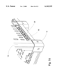
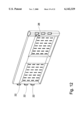
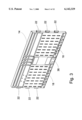
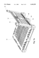
- FIG. 1 is a perspective view of a bin, constructed and operative according to the teachings of the present invention
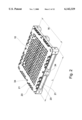
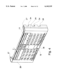
- FIG. 2 is a perspective view of a base from the bin of FIG. 1;
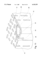
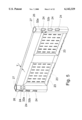
- FIG. 3 is an outer perspective view of a first side from the bin of FIG. 1;
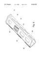
- FIG. 4 is an outer perspective view of a second side from the bin of FIG. 1;
- FIG. 5 is an inner perspective view of the second side of FIG. 4;
- FIG. 6 is a perspective view of a locking element from the bin of FIG. 1;
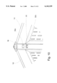
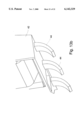
- FIG. 7A is a perspective view showing one of the second sides during attachment to the base
- FIG. 7B is a perspective view similar to FIG. 7A after attachment of the second sides to the base;
- FIG. 7C is an enlargement of a portion of FIG. 7A
- FIG. 7D is an enlargement of a portion of FIG. 7B;
- FIG. 7E is a partially cut-away enlargement of a portion of FIG. 7B;
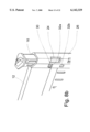
- FIGS. 8A and 8B are perspective views showing the locking element of FIG. 6 before and after insertion to an unlocked position within a vertical channel in a corner post of the second side of FIG. 4;
- FIGS. 9A-9C are a series of perspective views showing the positioning of adjacent sides and sliding of the locking element from an unlocked position to a locked position in which is locks together the first and second sides of the bin;
- FIG. 10 is an internal perspective view of the assembled bin showing the locking element in its locked position
- FIG. 11 is an enlarged, partially cut-away, perspective view showing the engagement of the locking element to connect together the first and second sides;
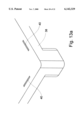
- FIG. 12 is a perspective view of a side from a variant implementation of the bin of FIG. 1;
- FIGS. 13A and 13B are schematic perspective views of part of a base and a side from a second variant of the bin of FIG. 1;
- FIG. 14 is a schematic perspective view of a fixed-walled bin with a fold-down wall portion implemented using a locking configuration according to the teachings of the present invention.
- the present invention is a knock-down bin.
- FIGS. 1-11 show a knock-down bin, constructed and operative according to the teachings of the present invention, preferably formed from polymer materials.
- the knock-down bin includes a substantially rectangular base 10 having a length L and a width W, a first two sides 14 associated with base 10 for deploying parallel to the length and a second two sides 12 associated with base 10 for deploying parallel to the width.
- Sides 12 and 14 meet to define four vertical corner portions. At least one of these corner portions, and preferably all four, are provided with a locking element 16 deployable to lock together adjacent sides.
- the corner portion includes a hollow vertical corner post 26 integrally formed with one of the sides, corner post 26 having a vertical hollow channel 27 into which opens a lateral opening 24.
- a projection 22, integrally formed with the other side making up the corner portion, is configured to project through lateral opening 24 into vertical channel 27.
- Locking element 16 is slidingly deployable within vertical channel 27 between an unlocked position (FIGS. 9A and 9B) in which projection 22 can be inserted and removed from lateral opening 24 and a locked position (FIG. 9C) in which locking element 16 engages projection 22 so as to lock it within channel 27, thereby locking together the adjacent first and second sides 12 and 14.
- the locking arrangement of the present invention provides a convenient and effective solution to various shortcomings of the prior art. Specifically, by employing a locking element which may be housed within vertical channel 27 even when in its unlocked position, the number of separate elements to be transported in the collapsed state is minimized. Furthermore, since locking element 16, when in its unlocked position, does not obstruct lateral opening 24, sides 12 and 14 can be conveniently positioned in their upright positions without complicated maneuvering and coordination. Additionally, the locked configuration provides a strong and secure interconnection suitable for relatively heavy duty applications. In a preferred case of a large bin where at least three T-shaped projections 22 are locked within slots 28 of locking element 16 at each corner, degree of rigidity approaching that of a solid molded bin is achieved.
- base 10 is described as "substantially rectangular” to the extent that the resulting bin assumes an overall rectangular form. It should be noted however that the external outline of the edges of the base need not closely resemble a rectangle. Variations from a regular rectangular shape are frequently caused by the form of reinforcing ribs and other features specific to various intended applications.
- sides 12 and 14 preferably feature a lower edge configured for detachable engagement with base 10.
- the form of engagement between sides 12 and 14 and base 10 is configured such that the sides are engagable with, and disengagable from, base 10 while being held in an inclined position relative to the base, but become locked in engagement with base 10 when raised to an upright position.
- FIGS. 2-4 and 7A-7E One preferred example of such an engagement configuration will now be described with particular reference to FIGS. 2-4 and 7A-7E.
- base 10 here features a row of hook brackets 20 spaced along each side. Inwardly spaced on base 10 from brackets 20 are a row of abutment ridges 21. As seen in FIGS. 3 and 4, the outside lower edge of sides 12 and 14 features a row of recesses located to correspond to brackets 20 and configured to provide upward-facing engagement surfaces 18.
- Attachment of the sides is then achieved by positioning each side in an outwardly-sloping position, as shown in FIGS. 7A and 7C, with engagement surfaces 18 aligned with brackets 20 and erecting the side to the position shown in FIGS. 7B, 7D and 7E so that engagement surfaces 18 become locked under brackets 20.
- Abutment ridges 21 abut the inner face of the side, preferably engaging corresponding rear sockets 23 (see FIG. 5), thereby preventing the side from slipping away from brackets 20 and limiting longitudinal movement of the sides along the line of contact with base 10.
- one or more alignment feature in this case an alignment projection 34 (see FIG. 2), is provided on base 10.
- the alignment feature is configured to engage with a corresponding alignment feature, in this case alignment recess 36 (see FIGS. 3 and 4), to help center and otherwise align the sides during positioning in the inclined position of FIG. 7A.
- projections 22 of one side are located within the lateral openings 24 of the adjacent side.
- projections 22 and openings 24 are configured such that the adjacent sides may be erected in any arbitrary order, thereby rendering the assembly process particularly easy and convenient.
- the locking configuration of the present invention may also be used to advantage with a range of other implementations.
- other possible implementations include, but are not limited to: foldable containers in which one or more side is hingedly connected to the base; and fixed-walled containers with one or more wall, or part of a wall, which is removable or foldable for loading and unloading or for display.
- the locking configuration of the present invention may be employed to secure together all of the corner portions between adjacent sides of which at least one (or part thereof) moves.
- the locking configuration of the invention may be used to advantage in combination with conventional locking arrangements.
- An example of such an implementation would be a knock-down container in which the sides interlock when assembled in a specific sequence, the locking configuration of the present invention being used only to secure the last corner of the structure.
- Locking element 16 features a number of slots 28 corresponding to the number of lateral openings 24 in vertical post 26. For large bins, this number is preferably at least three. For lightweight applications or for smaller bins (such as for domestic storage and the like), one or two points of engagement may be used.
- locking elements 16 are double-sided, i.e., with two sets of slots 28. This allows the use of identical locking elements 16 for each corner without the need to distinguish between right-side and left-side attachment. In the structure shown, only one set of slots 28 is operative at any time, as may be observed from the cross-sectional view of FIG. 11.
- locking element 16 remains housed within vertical channel 27 when in its unlocked position, thereby reducing the number of separate elements to be handled. Additionally, it is preferable that locking element 16 be retained in its unlocked position during attachment of sides 12 and 14 to avoid the need for complicated maneuvering and coordination to open element 16 while raising the sides. In the preferred implementation illustrated, this is achieved by providing locking element 16 with a resilient tab 30 configured to engage a corresponding first locating aperture 32a in corner post 26. First locating aperture 32a is positioned such that, when locking element 16 is in its unlocked position, resilient tab 30 engages first locating aperture 32a so as to retain locking element 16 in its unlocked position (see FIG. 8B). Clearly, a reversed implementation, having a tab associated with post 26 engaging a recess in locking element 16, would be functionally equivalent.
- a second locating aperture 32b is preferably positioned such that, when locking element 16 is in its locked position, resilient tab 30 engages second locating aperture 32b so as to retain locking element 16 in its locked position (see FIG. 10).
- first and second locating apertures 32a and 32b serve somewhat distinct functions as has been described, most preferred implementations of the bin of the present invention feature both, thereby ensuring that locking element 16 is always positively and securely retained in the desired position.
- a reversed implementation having one or two tabs associated with post 26 engaging one or two recesses in locking element 16, would be functionally equivalent.
- Another feature of preferred implementations of the present invention is that the sides of the bin, when separated, fit within another similar assembled bin, thereby facilitating convenient and compact return transport of the bins when not in use.
- this is achieved by forming all of the corner posts 26 as part of sides 12 which run parallel to the width.
- the length of sides 12 is equal to the external width W.
- the length of sides 14 is then less than external length L by twice the difference between the corresponding dimension of corner posts 26 and the length of projections 22. So long as this maximum length is chosen to be less than the length L by at least twice a thickness T of second sides 12, both types of sides can be accommodated parallel to the length within another similar bin.
- this storage configuration is effective independent of the relative proportions between the height of the sides and the dimensions of the base.
- An example of a side for such a structure is shown in FIG. 12.
- all four sides are identical, each including one corner post 26. Since all of the interconnections are the same "handedness" (i.e., post 26 on the right and projections 22 on the left, or the reverse), locking element 16 can be simplified to a non-symmetric form (not shown) with only one set of slots 28.
- this implementation is fully analogous to that of FIGS. 1-11.
- FIG. 14 shows a fixed-wall stackable bin 50 with a fold-down panel 52 for display purposes.
- panel 52 is hinged along its lower edge to a fixed lower part of a wall.
- the panel is releasably securable to the rest of the structure by use of two locking configurations which are fully analogous to the structures described in the preceding embodiments.
Landscapes
- Engineering & Computer Science (AREA)
- Mechanical Engineering (AREA)
- Rigid Containers With Two Or More Constituent Elements (AREA)
- Preparation Of Clay, And Manufacture Of Mixtures Containing Clay Or Cement (AREA)
- Housing For Livestock And Birds (AREA)
- Packaging Of Annular Or Rod-Shaped Articles, Wearing Apparel, Cassettes, Or The Like (AREA)
- Details Of Rigid Or Semi-Rigid Containers (AREA)
- Electrical Control Of Ignition Timing (AREA)
- Packages (AREA)
- Containers And Packaging Bodies Having A Special Means To Remove Contents (AREA)
Abstract
Description
Claims (11)
Priority Applications (9)
| Application Number | Priority Date | Filing Date | Title |
|---|---|---|---|
| US09/494,042 US6142329A (en) | 2000-01-31 | 2000-01-31 | Knock-down bin |
| IL15057601A IL150576A0 (en) | 2000-01-31 | 2001-01-04 | Knock-down bin |
| EP01901710A EP1286895B1 (en) | 2000-01-31 | 2001-01-04 | Knock-down bin |
| DE60124701T DE60124701T2 (en) | 2000-01-31 | 2001-01-04 | COLLAPSIBLE CONTAINER |
| PCT/US2001/000194 WO2001054992A1 (en) | 2000-01-31 | 2001-01-04 | Knock-down bin |
| AU2001227583A AU2001227583A1 (en) | 2000-01-31 | 2001-01-04 | Knock-down bin |
| AT01901710T ATE345982T1 (en) | 2000-01-31 | 2001-01-04 | COLLAPSIBLE CONTAINER |
| US10/086,435 US6761277B2 (en) | 2000-01-31 | 2002-03-04 | Square knock-down bin |
| ZA200205356A ZA200205356B (en) | 2000-01-31 | 2002-07-04 | Knock-down bin. |
Applications Claiming Priority (1)
| Application Number | Priority Date | Filing Date | Title |
|---|---|---|---|
| US09/494,042 US6142329A (en) | 2000-01-31 | 2000-01-31 | Knock-down bin |
Related Child Applications (2)
| Application Number | Title | Priority Date | Filing Date |
|---|---|---|---|
| PCT/US2001/000194 Continuation-In-Part WO2001054992A1 (en) | 2000-01-31 | 2001-01-04 | Knock-down bin |
| US10/086,435 Continuation-In-Part US6761277B2 (en) | 2000-01-31 | 2002-03-04 | Square knock-down bin |
Publications (1)
| Publication Number | Publication Date |
|---|---|
| US6142329A true US6142329A (en) | 2000-11-07 |
Family
ID=23962780
Family Applications (2)
| Application Number | Title | Priority Date | Filing Date |
|---|---|---|---|
| US09/494,042 Expired - Lifetime US6142329A (en) | 2000-01-31 | 2000-01-31 | Knock-down bin |
| US10/086,435 Expired - Fee Related US6761277B2 (en) | 2000-01-31 | 2002-03-04 | Square knock-down bin |
Family Applications After (1)
| Application Number | Title | Priority Date | Filing Date |
|---|---|---|---|
| US10/086,435 Expired - Fee Related US6761277B2 (en) | 2000-01-31 | 2002-03-04 | Square knock-down bin |
Country Status (8)
| Country | Link |
|---|---|
| US (2) | US6142329A (en) |
| EP (1) | EP1286895B1 (en) |
| AT (1) | ATE345982T1 (en) |
| AU (1) | AU2001227583A1 (en) |
| DE (1) | DE60124701T2 (en) |
| IL (1) | IL150576A0 (en) |
| WO (1) | WO2001054992A1 (en) |
| ZA (1) | ZA200205356B (en) |
Cited By (49)
| Publication number | Priority date | Publication date | Assignee | Title |
|---|---|---|---|---|
| USD452614S1 (en) | 2000-10-28 | 2002-01-01 | Rehrig Pacific Company | Collapsible container |
| USD458753S1 (en) | 2000-09-21 | 2002-06-18 | Rehrig Pacific Co. | Container |
| US6409041B1 (en) | 2000-09-21 | 2002-06-25 | Rehrig Pacific Company | Container |
| US20020108950A1 (en) * | 2001-02-14 | 2002-08-15 | Moorman Stephen E. | Collapsible container |
| US6585126B1 (en) * | 2001-12-11 | 2003-07-01 | North American Container Corporation | Returnable crate |
| US6631822B1 (en) | 2000-10-28 | 2003-10-14 | Rehrig Pacific Company | Collapsible container |
| US6631821B2 (en) | 2000-10-31 | 2003-10-14 | Peter N. Vourganas | Reinforced double-wall knock-down bin |
| US20030222081A1 (en) * | 2002-05-28 | 2003-12-04 | Apps William P. | Collapsibile crate with support members |
| US20040069780A1 (en) * | 2002-10-11 | 2004-04-15 | Rehrig Pacific Company | Portable storage device |
| US20040178197A1 (en) * | 2003-03-10 | 2004-09-16 | Rehrig Pacific Company | Collapsible container |
| US20040182858A1 (en) * | 2003-03-21 | 2004-09-23 | Rehrig Pacific Company | Collapsible container |
| US20040226945A1 (en) * | 2003-05-13 | 2004-11-18 | Hsu Roger S | Collapsible container |
| DE10345285A1 (en) * | 2003-09-30 | 2005-04-21 | Ralf Schneeberger | Heavy duty plastic transporting box for commercial haulage and warehouse logistics is collapsible, sealable, light and stackable, and side walls and bottom have high stability by specific ribbing |
| AU783052B2 (en) * | 2002-03-25 | 2005-09-22 | Dolav Dvir Lahav Plastic Products | Square knock-down bin |
| US20050230392A1 (en) * | 2004-04-19 | 2005-10-20 | Polymer Logistics (Israel) Ltd. | Knock-down crate with walls stored in base and method employing such a crate |
| WO2005100176A2 (en) | 2004-04-19 | 2005-10-27 | Polymer Logistics (Israel) Ltd. | Knock-down crate with walls stored in base and method employing such a crate |
| US20060054528A1 (en) * | 2004-08-30 | 2006-03-16 | Sanzana Cecil M | Foldable plastic box, assemblable, having 5 cavities, with or without folding upper covers, to contain agricultural products |
| DE102005027114A1 (en) * | 2005-06-10 | 2006-12-14 | Tara Verpackungstechnologie Gmbh | Load carrier composed of strips, for transporting and storing loads has strips formed from two shaped halves fixed to each other to form hollow strip |
| US20070095842A1 (en) * | 2005-11-01 | 2007-05-03 | Apps William P | Container |
| US20070095692A1 (en) * | 2005-11-01 | 2007-05-03 | Apps William P | Container |
| WO2007129988A1 (en) * | 2006-05-08 | 2007-11-15 | Caddee Pte Ltd | Collapsible container |
| US20070272579A1 (en) * | 2006-05-24 | 2007-11-29 | Rehrig Pacific Company | Collapsible crate with support members |
| US20080017081A1 (en) * | 2006-07-24 | 2008-01-24 | Rehrig Pacific Company | Pallet assembly |
| US20080116201A1 (en) * | 2006-11-17 | 2008-05-22 | Kyle Baltz | Container |
| US20080169285A1 (en) * | 2007-01-16 | 2008-07-17 | Nick Marazita | Collapsible container |
| FR2913008A1 (en) * | 2007-02-27 | 2008-08-29 | Rehau Sa | Plastic panel for forming wall of e.g. cubical shaped container, has hollow piece with receiving site extending between lateral edges of panel and receiving elongated reinforcement element that stiffens and rigidifies adapted section |
| US20080302791A1 (en) * | 2007-06-11 | 2008-12-11 | Baltz Kyle L | Collapsible Container |
| US20090032530A1 (en) * | 2007-07-30 | 2009-02-05 | Pacific Container Network, Inc. | Joint structure for portable work and storage container |
| US7717283B2 (en) | 2007-11-06 | 2010-05-18 | Rehrig Pacific Company | Collapsible container |
| WO2010089014A1 (en) * | 2009-02-04 | 2010-08-12 | Schoeller Arca Systems Gmbh | Heavy load carrier |
| US20120067884A1 (en) * | 2010-09-21 | 2012-03-22 | Hathaway Richard C | Unit load device and container for transporting cargo |
| EP2439146A1 (en) * | 2010-10-11 | 2012-04-11 | CLADI GmbH | Container for the transportation and/or storage of perishable goods |
| US20120285951A1 (en) * | 2011-05-11 | 2012-11-15 | Cavalcante Mauricio D | Collapsible crate |
| US20130181590A1 (en) * | 2012-01-18 | 2013-07-18 | Shun-Teng Chen | Combination Drawer |
| US20150284135A1 (en) * | 2014-04-08 | 2015-10-08 | Wenco S.A. | Light and integrated junction system of the walls of a collapsible container |
| US20150283745A1 (en) * | 2014-04-08 | 2015-10-08 | Wenco S.A. | Bottom of a container that optimizes the use of material |
| US20160046405A1 (en) * | 2014-08-12 | 2016-02-18 | Meixin Manufacturing Co., Ltd. | Plug-in type container |
| USD802926S1 (en) | 2016-08-31 | 2017-11-21 | Macro Plastics, Inc. | Shipping container |
| USD816997S1 (en) * | 2015-11-23 | 2018-05-08 | Macro Plastics, Inc. | Shipping container |
| US20180346189A1 (en) * | 2017-06-02 | 2018-12-06 | Wenco S.A. | Plastic container column having an upper widening and a lower projection; wherein the lower projection is half ellipse shaped comprising a conicity |
| US10167110B2 (en) | 2010-05-27 | 2019-01-01 | Rehrig Pacific Company | Dual height collapsible container |
| US10703531B2 (en) | 2016-03-11 | 2020-07-07 | Rehrig Pacific Company | Collapsible crate with wood appearance |
| US11459145B2 (en) * | 2016-05-24 | 2022-10-04 | Shanghai Hongyan Returnable Transit Packagings Co., Ltd. | Collapsable box |
| US11597557B2 (en) | 2018-10-04 | 2023-03-07 | Rehrig Pacific Company | Reconfigurable beverage crate |
| USD1028521S1 (en) | 2022-08-25 | 2024-05-28 | Tw America Inc. | Storage basket |
| US20240374053A1 (en) * | 2023-01-18 | 2024-11-14 | Kawajun Co., Ltd. | Foldable display case |
| US20240389769A1 (en) * | 2023-01-18 | 2024-11-28 | Kawajun Co., Ltd. | Display case |
| US12168544B2 (en) | 2021-09-16 | 2024-12-17 | Rehrig Pacific Company | Hybrid collapsible crate |
| US12448172B2 (en) | 2018-03-05 | 2025-10-21 | Rehrig Pacific Company | Collapsible container |
Families Citing this family (12)
| Publication number | Priority date | Publication date | Assignee | Title |
|---|---|---|---|---|
| AU2003227022A1 (en) * | 2003-03-13 | 2004-09-30 | Paul Klinge Group A/S | Container |
| ATE387378T1 (en) * | 2003-09-15 | 2008-03-15 | Marcos Rodriguez | COLLAPSIBLE CONTAINER |
| DE102004023831B4 (en) * | 2004-05-13 | 2009-09-03 | Aco Severin Ahlmann Gmbh & Co. Kg | Covered plastic bar |
| US20080083636A1 (en) * | 2006-10-10 | 2008-04-10 | Devine Timothy A | Stackable plant carrying system |
| US20090242554A1 (en) * | 2007-08-27 | 2009-10-01 | Reality Group, Inc. | Reusable container |
| DE102008047229A1 (en) * | 2008-09-12 | 2010-03-25 | Freigeber, Jürgen | Separating walls for inserting box shaped container in multiple compartments for receiving oblong products, particularly crate, have multiple adjacent, knife shaped, different height sections in area of upper edge |
| DE102009041436A1 (en) * | 2009-09-16 | 2011-03-24 | Cabka Gmbh | Loading carrier i.e. flat plastic pallet, for use in dismountable container to store melon, has deck limited by edges, and container wall support unit arranged at edges to support container wall, where support unit is mounted on carrier |
| US8770421B2 (en) * | 2010-01-28 | 2014-07-08 | Nova Chemicals (International) S.A. | Collapsible refuse bin |
| EP2431287B1 (en) * | 2010-09-20 | 2013-07-24 | IFCO Systems GmbH | Crate |
| ITPC20130018A1 (en) * | 2013-06-03 | 2014-12-04 | Cristiano Ricchetti | UNBELIEVABLE CONTAINER |
| BE1022645B1 (en) * | 2014-05-12 | 2016-06-23 | FACIL CORPORATE, besloten vennootschap met beperkte aansprakelijkheid | REUSABLE AND STACKABLE TRAY FOR STORING AND / OR TRANSPORTING GOODS |
| JP7075698B1 (en) | 2022-01-12 | 2022-05-26 | ミクニ機工株式会社 | Heat treatment container and its manufacturing method |
Citations (13)
| Publication number | Priority date | Publication date | Assignee | Title |
|---|---|---|---|---|
| US1828088A (en) * | 1928-10-08 | 1931-10-20 | Benjamin F Lyons | Container construction |
| US3374915A (en) * | 1966-07-21 | 1968-03-26 | Verhein Donald | Collapsible and stackable container |
| US3401814A (en) * | 1967-03-07 | 1968-09-17 | Collapsible Container Corp | Collapsible shipping container |
| US4128354A (en) * | 1977-01-13 | 1978-12-05 | Erich Amrogowicz | Knock-down container side panel connections |
| US4662532A (en) * | 1985-11-04 | 1987-05-05 | Steel King Industries, Inc. | Foldable container |
| US4828132A (en) * | 1987-07-28 | 1989-05-09 | United States Corrulite Corporation | Collapsible reusable containers, wall sleeves and hinges therefor |
| US5031794A (en) * | 1989-08-01 | 1991-07-16 | Shell Research Limited | Container for elastic solid material |
| US5094356A (en) * | 1990-11-13 | 1992-03-10 | Buckhorn Material Handling Group, Inc. | Knock down bulk container |
| US5452817A (en) * | 1994-01-13 | 1995-09-26 | Anchor Bay Packaging Corporation | Stackable bin with collapsible corner construction |
| US5505323A (en) * | 1993-10-01 | 1996-04-09 | Kabushiki Kaisha Steel Center | Container capable of being assembled by interlocking connections |
| US5529199A (en) * | 1995-02-22 | 1996-06-25 | Foster; Hensley | Container capable of disassembly into an integral unit following use |
| US5638973A (en) * | 1996-05-09 | 1997-06-17 | Western Poly Corporation | Storage container with interlocking corner members |
| US5642830A (en) * | 1995-02-22 | 1997-07-01 | Badger Case, Inc. | Collapsible container with latch mechanism |
Family Cites Families (20)
| Publication number | Priority date | Publication date | Assignee | Title |
|---|---|---|---|---|
| US1482926A (en) | 1922-06-30 | 1924-02-05 | Newton S Hillyard | Refuse receptacle |
| US2119799A (en) | 1937-04-15 | 1938-06-07 | William F Sivey | Collapsible stove |
| US2942749A (en) | 1956-03-22 | 1960-06-28 | Harold W Rosenberg | Sectionalized metal chassis for electronic equipment |
| US3184095A (en) | 1959-05-28 | 1965-05-18 | Reynolds Metals Co | Carrying case for bottle cartons and the like |
| US3447490A (en) * | 1966-12-30 | 1969-06-03 | Palletower Ltd | Frames for stacking pallets |
| NL156365B (en) * | 1973-12-11 | 1978-04-17 | Hans Adolf Bakkeren | HOLDER FOR KEEPING A STACK OF SHEET MATERIAL, SUCH AS PAPER, DURING TRANSPORTATION AND STRAPING THAT STACK. |
| DE2510253A1 (en) * | 1975-03-08 | 1976-09-16 | Erich Ing Grad Amrogowicz | Pallet frame with removable sides - lockable to adjacent sides with integral columns having slots for locking bolts on removable sides |
| US4334359A (en) * | 1977-11-04 | 1982-06-15 | Kump Ernest J | Containers |
| US4184602A (en) * | 1978-05-30 | 1980-01-22 | Henry Moliard | Collapsible expansible container |
| US4809851A (en) | 1987-04-03 | 1989-03-07 | World Container Corporation | Collapsible container |
| US4955499A (en) * | 1988-11-21 | 1990-09-11 | Fiberlite | Receptacle update device |
| US5056677A (en) * | 1989-11-09 | 1991-10-15 | Daiya Sangyo Co., Ltd. | Small article holders |
| US5193714A (en) | 1992-06-25 | 1993-03-16 | The Neel Company | Modular vault for storage tanks |
| US5236099A (en) | 1992-08-19 | 1993-08-17 | Fties Youssef A | Plastic knockdown bin-pallet for loading, transporting and storing fruits, vegetables, fish or other foods |
| US5474195A (en) * | 1995-01-24 | 1995-12-12 | Pai; Ming Y. | Built-up basket |
| US5971187A (en) * | 1995-12-15 | 1999-10-26 | Clee; Michael | Hinge for a collapsible container |
| PT786412E (en) | 1996-01-26 | 2002-06-28 | Bekuplast Gmbh | TRANSPORTATION AND STORAGE CONTAINER |
| EP0947434A3 (en) * | 1998-04-02 | 2002-03-20 | Noel Ivor Yule | Container and container panels |
| US6311858B1 (en) * | 2000-04-25 | 2001-11-06 | Joe Csiszar | Adjustable length, modular storage device |
| US6189695B1 (en) | 2000-05-04 | 2001-02-20 | Ching-Rong Liu | Structure for foldable storage bins |
-
2000
- 2000-01-31 US US09/494,042 patent/US6142329A/en not_active Expired - Lifetime
-
2001
- 2001-01-04 EP EP01901710A patent/EP1286895B1/en not_active Expired - Lifetime
- 2001-01-04 AU AU2001227583A patent/AU2001227583A1/en not_active Abandoned
- 2001-01-04 IL IL15057601A patent/IL150576A0/en not_active IP Right Cessation
- 2001-01-04 WO PCT/US2001/000194 patent/WO2001054992A1/en not_active Ceased
- 2001-01-04 DE DE60124701T patent/DE60124701T2/en not_active Expired - Lifetime
- 2001-01-04 AT AT01901710T patent/ATE345982T1/en not_active IP Right Cessation
-
2002
- 2002-03-04 US US10/086,435 patent/US6761277B2/en not_active Expired - Fee Related
- 2002-07-04 ZA ZA200205356A patent/ZA200205356B/en unknown
Patent Citations (13)
| Publication number | Priority date | Publication date | Assignee | Title |
|---|---|---|---|---|
| US1828088A (en) * | 1928-10-08 | 1931-10-20 | Benjamin F Lyons | Container construction |
| US3374915A (en) * | 1966-07-21 | 1968-03-26 | Verhein Donald | Collapsible and stackable container |
| US3401814A (en) * | 1967-03-07 | 1968-09-17 | Collapsible Container Corp | Collapsible shipping container |
| US4128354A (en) * | 1977-01-13 | 1978-12-05 | Erich Amrogowicz | Knock-down container side panel connections |
| US4662532A (en) * | 1985-11-04 | 1987-05-05 | Steel King Industries, Inc. | Foldable container |
| US4828132A (en) * | 1987-07-28 | 1989-05-09 | United States Corrulite Corporation | Collapsible reusable containers, wall sleeves and hinges therefor |
| US5031794A (en) * | 1989-08-01 | 1991-07-16 | Shell Research Limited | Container for elastic solid material |
| US5094356A (en) * | 1990-11-13 | 1992-03-10 | Buckhorn Material Handling Group, Inc. | Knock down bulk container |
| US5505323A (en) * | 1993-10-01 | 1996-04-09 | Kabushiki Kaisha Steel Center | Container capable of being assembled by interlocking connections |
| US5452817A (en) * | 1994-01-13 | 1995-09-26 | Anchor Bay Packaging Corporation | Stackable bin with collapsible corner construction |
| US5529199A (en) * | 1995-02-22 | 1996-06-25 | Foster; Hensley | Container capable of disassembly into an integral unit following use |
| US5642830A (en) * | 1995-02-22 | 1997-07-01 | Badger Case, Inc. | Collapsible container with latch mechanism |
| US5638973A (en) * | 1996-05-09 | 1997-06-17 | Western Poly Corporation | Storage container with interlocking corner members |
Cited By (75)
| Publication number | Priority date | Publication date | Assignee | Title |
|---|---|---|---|---|
| USD458753S1 (en) | 2000-09-21 | 2002-06-18 | Rehrig Pacific Co. | Container |
| US6409041B1 (en) | 2000-09-21 | 2002-06-25 | Rehrig Pacific Company | Container |
| US7086555B2 (en) | 2000-09-21 | 2006-08-08 | Rehrig Pacific Company | Container |
| USD478421S1 (en) | 2000-09-21 | 2003-08-19 | Rehrig Pacific Company | Container |
| US20040099662A1 (en) * | 2000-10-28 | 2004-05-27 | Rehrig Pacific Company | Collapsible container |
| US7128231B2 (en) | 2000-10-28 | 2006-10-31 | Rehrig Pacific Company | Collapsible container |
| US6631822B1 (en) | 2000-10-28 | 2003-10-14 | Rehrig Pacific Company | Collapsible container |
| USD452614S1 (en) | 2000-10-28 | 2002-01-01 | Rehrig Pacific Company | Collapsible container |
| US6631821B2 (en) | 2000-10-31 | 2003-10-14 | Peter N. Vourganas | Reinforced double-wall knock-down bin |
| US20020108950A1 (en) * | 2001-02-14 | 2002-08-15 | Moorman Stephen E. | Collapsible container |
| US6585126B1 (en) * | 2001-12-11 | 2003-07-01 | North American Container Corporation | Returnable crate |
| AU783052B2 (en) * | 2002-03-25 | 2005-09-22 | Dolav Dvir Lahav Plastic Products | Square knock-down bin |
| US7478726B2 (en) | 2002-05-28 | 2009-01-20 | Rehrig Pacific Company | Collapsibile crate with support members |
| US20030222081A1 (en) * | 2002-05-28 | 2003-12-04 | Apps William P. | Collapsibile crate with support members |
| US7059489B2 (en) | 2002-10-11 | 2006-06-13 | Rehrig Pacific Company | Portable storage device |
| US20040069780A1 (en) * | 2002-10-11 | 2004-04-15 | Rehrig Pacific Company | Portable storage device |
| US20040178197A1 (en) * | 2003-03-10 | 2004-09-16 | Rehrig Pacific Company | Collapsible container |
| US7017766B2 (en) | 2003-03-10 | 2006-03-28 | Rehrig Pacific Company | Collapsible container with side wall latching capability |
| US7100786B2 (en) | 2003-03-21 | 2006-09-05 | Rehrig Pacific Company | Collapsible container |
| US20040182858A1 (en) * | 2003-03-21 | 2004-09-23 | Rehrig Pacific Company | Collapsible container |
| US20040226945A1 (en) * | 2003-05-13 | 2004-11-18 | Hsu Roger S | Collapsible container |
| US7195127B2 (en) | 2003-05-13 | 2007-03-27 | Rehrig Pacific Company | Collapsible container |
| DE10345285A1 (en) * | 2003-09-30 | 2005-04-21 | Ralf Schneeberger | Heavy duty plastic transporting box for commercial haulage and warehouse logistics is collapsible, sealable, light and stackable, and side walls and bottom have high stability by specific ribbing |
| US20050230392A1 (en) * | 2004-04-19 | 2005-10-20 | Polymer Logistics (Israel) Ltd. | Knock-down crate with walls stored in base and method employing such a crate |
| WO2005100176A2 (en) | 2004-04-19 | 2005-10-27 | Polymer Logistics (Israel) Ltd. | Knock-down crate with walls stored in base and method employing such a crate |
| US7281637B2 (en) | 2004-04-19 | 2007-10-16 | Polymer Logistics (Israel) Ltd. | Knock-down crate with walls stored in base and method employing such a crate |
| US20060054528A1 (en) * | 2004-08-30 | 2006-03-16 | Sanzana Cecil M | Foldable plastic box, assemblable, having 5 cavities, with or without folding upper covers, to contain agricultural products |
| DE102005027114A1 (en) * | 2005-06-10 | 2006-12-14 | Tara Verpackungstechnologie Gmbh | Load carrier composed of strips, for transporting and storing loads has strips formed from two shaped halves fixed to each other to form hollow strip |
| US20070095692A1 (en) * | 2005-11-01 | 2007-05-03 | Apps William P | Container |
| US20070194023A1 (en) * | 2005-11-01 | 2007-08-23 | Apps William P | Container |
| US7357269B2 (en) | 2005-11-01 | 2008-04-15 | Rehrig Pacific Company | Container |
| US20080142399A1 (en) * | 2005-11-01 | 2008-06-19 | Apps William P | Container |
| US20070095842A1 (en) * | 2005-11-01 | 2007-05-03 | Apps William P | Container |
| US7726502B2 (en) | 2005-11-01 | 2010-06-01 | Rehrig Pacific Company | Container |
| WO2007129988A1 (en) * | 2006-05-08 | 2007-11-15 | Caddee Pte Ltd | Collapsible container |
| US20070272579A1 (en) * | 2006-05-24 | 2007-11-29 | Rehrig Pacific Company | Collapsible crate with support members |
| US20080017081A1 (en) * | 2006-07-24 | 2008-01-24 | Rehrig Pacific Company | Pallet assembly |
| US20100212553A1 (en) * | 2006-07-24 | 2010-08-26 | Baltz Kyle L | Pallet assembly |
| US7748329B2 (en) | 2006-07-24 | 2010-07-06 | Rehrig Pacific Company | Pallet assembly |
| US20080116201A1 (en) * | 2006-11-17 | 2008-05-22 | Kyle Baltz | Container |
| US20080169285A1 (en) * | 2007-01-16 | 2008-07-17 | Nick Marazita | Collapsible container |
| FR2913008A1 (en) * | 2007-02-27 | 2008-08-29 | Rehau Sa | Plastic panel for forming wall of e.g. cubical shaped container, has hollow piece with receiving site extending between lateral edges of panel and receiving elongated reinforcement element that stiffens and rigidifies adapted section |
| US7641066B2 (en) | 2007-06-11 | 2010-01-05 | Rehrig Pacific Company | Collapsible container |
| US20080302791A1 (en) * | 2007-06-11 | 2008-12-11 | Baltz Kyle L | Collapsible Container |
| US20090032530A1 (en) * | 2007-07-30 | 2009-02-05 | Pacific Container Network, Inc. | Joint structure for portable work and storage container |
| US7717283B2 (en) | 2007-11-06 | 2010-05-18 | Rehrig Pacific Company | Collapsible container |
| WO2010089014A1 (en) * | 2009-02-04 | 2010-08-12 | Schoeller Arca Systems Gmbh | Heavy load carrier |
| US10167110B2 (en) | 2010-05-27 | 2019-01-01 | Rehrig Pacific Company | Dual height collapsible container |
| US20120067884A1 (en) * | 2010-09-21 | 2012-03-22 | Hathaway Richard C | Unit load device and container for transporting cargo |
| EP2439146A1 (en) * | 2010-10-11 | 2012-04-11 | CLADI GmbH | Container for the transportation and/or storage of perishable goods |
| US20120285951A1 (en) * | 2011-05-11 | 2012-11-15 | Cavalcante Mauricio D | Collapsible crate |
| US20130181590A1 (en) * | 2012-01-18 | 2013-07-18 | Shun-Teng Chen | Combination Drawer |
| US20150284135A1 (en) * | 2014-04-08 | 2015-10-08 | Wenco S.A. | Light and integrated junction system of the walls of a collapsible container |
| CN104973348A (en) * | 2014-04-08 | 2015-10-14 | 温克公司 | Light And Integrated Junction System Of The Walls Of A Collapsible Container |
| CN105035555A (en) * | 2014-04-08 | 2015-11-11 | 温克公司 | Bottom of a container that optimizes the use of material |
| AU2015201265B2 (en) * | 2014-04-08 | 2019-12-05 | Wenco S.A. | Light and integrated junction system of the walls of a collapsible container |
| US20150283745A1 (en) * | 2014-04-08 | 2015-10-08 | Wenco S.A. | Bottom of a container that optimizes the use of material |
| CN104973348B (en) * | 2014-04-08 | 2019-06-25 | 温克公司 | The mating system being integrated into the wall of collapsible container |
| US10232978B2 (en) * | 2014-04-08 | 2019-03-19 | Wenco S.A. | Light and integrated junction system of the walls of a collapsible container |
| CN105035555B (en) * | 2014-04-08 | 2019-02-05 | 温克公司 | Optimize the bottom of the container for the use of materials |
| US20160046405A1 (en) * | 2014-08-12 | 2016-02-18 | Meixin Manufacturing Co., Ltd. | Plug-in type container |
| US10029184B2 (en) * | 2014-08-12 | 2018-07-24 | Meixin Manufacturing Co., Ltd. | Plug-in type container |
| USD816997S1 (en) * | 2015-11-23 | 2018-05-08 | Macro Plastics, Inc. | Shipping container |
| US10703531B2 (en) | 2016-03-11 | 2020-07-07 | Rehrig Pacific Company | Collapsible crate with wood appearance |
| US11459145B2 (en) * | 2016-05-24 | 2022-10-04 | Shanghai Hongyan Returnable Transit Packagings Co., Ltd. | Collapsable box |
| USD802926S1 (en) | 2016-08-31 | 2017-11-21 | Macro Plastics, Inc. | Shipping container |
| US20180346189A1 (en) * | 2017-06-02 | 2018-12-06 | Wenco S.A. | Plastic container column having an upper widening and a lower projection; wherein the lower projection is half ellipse shaped comprising a conicity |
| US10676234B2 (en) | 2017-06-02 | 2020-06-09 | Wenco S.A. | Plastic container below 450 gr for horticulture products exports |
| US12448172B2 (en) | 2018-03-05 | 2025-10-21 | Rehrig Pacific Company | Collapsible container |
| US11597557B2 (en) | 2018-10-04 | 2023-03-07 | Rehrig Pacific Company | Reconfigurable beverage crate |
| US12168544B2 (en) | 2021-09-16 | 2024-12-17 | Rehrig Pacific Company | Hybrid collapsible crate |
| USD1028521S1 (en) | 2022-08-25 | 2024-05-28 | Tw America Inc. | Storage basket |
| US20240374053A1 (en) * | 2023-01-18 | 2024-11-14 | Kawajun Co., Ltd. | Foldable display case |
| US20240389769A1 (en) * | 2023-01-18 | 2024-11-28 | Kawajun Co., Ltd. | Display case |
| US12383080B2 (en) * | 2023-01-18 | 2025-08-12 | Kawajun Co., Ltd. | Foldable display case |
Also Published As
| Publication number | Publication date |
|---|---|
| US6761277B2 (en) | 2004-07-13 |
| DE60124701T2 (en) | 2007-09-13 |
| EP1286895A4 (en) | 2005-06-01 |
| AU2001227583A1 (en) | 2001-08-07 |
| US20020084274A1 (en) | 2002-07-04 |
| DE60124701D1 (en) | 2007-01-04 |
| IL150576A0 (en) | 2003-02-12 |
| WO2001054992A1 (en) | 2001-08-02 |
| EP1286895B1 (en) | 2006-11-22 |
| ZA200205356B (en) | 2003-11-12 |
| EP1286895A1 (en) | 2003-03-05 |
| ATE345982T1 (en) | 2006-12-15 |
Similar Documents
| Publication | Publication Date | Title |
|---|---|---|
| US6142329A (en) | Knock-down bin | |
| US6722515B2 (en) | Folding crate | |
| US5862931A (en) | Collapsible shipping container | |
| US7281637B2 (en) | Knock-down crate with walls stored in base and method employing such a crate | |
| US7726496B2 (en) | Shipping and storage system | |
| US5865334A (en) | Collapsible container | |
| US20080179322A1 (en) | Bulk shipping container having adjustable height, collapsible walls | |
| WO2007111620A2 (en) | Automatically interlocking pallets, and shipping and storage systems employing the same | |
| JP2022524497A (en) | Cargo unit | |
| US7032765B2 (en) | Container with over center corner latches | |
| JP2002002696A (en) | Loading structure of folding container | |
| CA3028704A1 (en) | Foldable pallet deck | |
| EP1737737B1 (en) | Knock-down crate with walls stored in base and method employing such a crate | |
| AU783052B2 (en) | Square knock-down bin | |
| KR100673270B1 (en) | Folding pallet for automotive parts | |
| WO2003055755A2 (en) | Crates | |
| US20250376295A1 (en) | System Using Clips for Joining Container Sleeves | |
| CN222311178U (en) | Detachable storage cabinet | |
| WO1999033711A1 (en) | Collapsible container | |
| JPH0526035Y2 (en) | ||
| AU780669B2 (en) | Panel/gate interconnection means for a collapsible materials handling container | |
| JPH09267837A (en) | Pallet container | |
| JPH0339436Y2 (en) | ||
| JPH038584Y2 (en) | ||
| JPH10273139A (en) | Collapsible transfer case for article |
Legal Events
| Date | Code | Title | Description |
|---|---|---|---|
| AS | Assignment |
Owner name: DOLAV DVIR LAHAV PLASTIC PRODUCTS, ISRAEL Free format text: ASSIGNMENT OF ASSIGNORS INTEREST;ASSIGNOR:DOTAN, MOSHE;REEL/FRAME:010585/0027 Effective date: 20000126 |
|
| STCF | Information on status: patent grant |
Free format text: PATENTED CASE |
|
| FPAY | Fee payment |
Year of fee payment: 4 |
|
| FEPP | Fee payment procedure |
Free format text: PAT HOLDER CLAIMS SMALL ENTITY STATUS, ENTITY STATUS SET TO SMALL (ORIGINAL EVENT CODE: LTOS); ENTITY STATUS OF PATENT OWNER: SMALL ENTITY |
|
| FPAY | Fee payment |
Year of fee payment: 8 |
|
| FPAY | Fee payment |
Year of fee payment: 12 |