US6138842A - Point of sale display - Google Patents
Point of sale display Download PDFInfo
- Publication number
- US6138842A US6138842A US09/502,657 US50265700A US6138842A US 6138842 A US6138842 A US 6138842A US 50265700 A US50265700 A US 50265700A US 6138842 A US6138842 A US 6138842A
- Authority
- US
- United States
- Prior art keywords
- supporting walls
- elongated tubular
- tubular member
- lateral wall
- removably mounted
- Prior art date
- Legal status (The legal status is an assumption and is not a legal conclusion. Google has not performed a legal analysis and makes no representation as to the accuracy of the status listed.)
- Expired - Lifetime
Links
Images


Classifications
-
- A—HUMAN NECESSITIES
- A47—FURNITURE; DOMESTIC ARTICLES OR APPLIANCES; COFFEE MILLS; SPICE MILLS; SUCTION CLEANERS IN GENERAL
- A47F—SPECIAL FURNITURE, FITTINGS, OR ACCESSORIES FOR SHOPS, STOREHOUSES, BARS, RESTAURANTS OR THE LIKE; PAYING COUNTERS
- A47F5/00—Show stands, hangers, or shelves characterised by their constructional features
- A47F5/10—Adjustable or foldable or dismountable display stands
-
- A—HUMAN NECESSITIES
- A47—FURNITURE; DOMESTIC ARTICLES OR APPLIANCES; COFFEE MILLS; SPICE MILLS; SUCTION CLEANERS IN GENERAL
- A47F—SPECIAL FURNITURE, FITTINGS, OR ACCESSORIES FOR SHOPS, STOREHOUSES, BARS, RESTAURANTS OR THE LIKE; PAYING COUNTERS
- A47F5/00—Show stands, hangers, or shelves characterised by their constructional features
- A47F5/04—Stands with a central pillar, e.g. tree type
- A47F5/06—Stands with a central pillar, e.g. tree type adjustable
Definitions
- the present invention relates to point of sale displays, and more particularly, to displays that can be readily dismountable and used as a wheelbarrow.
- the present invention allows a user to store additional objects on the top tray such as documentation, electrical power supplies or batteries, sensors, lights and other electronic devices, to make the display smart and activate upon the detection of different conditions like the approach of a person (potential customer) and activating audio announcers or lights, or removal of products from the display (for the purposes of refilling or counting inventory), and keeping these devices out of the public's sight.
- additional objects on the top tray such as documentation, electrical power supplies or batteries, sensors, lights and other electronic devices
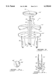
- FIG. 1 represents a tilted isometric view of one of the preferred embodiments of the invention in the point of sale display configuration.
- FIG. 2 shows a side elevational view of the invention in the wheelbarrow configuration.
- FIG. 3 is a tilted isometric view of an alternative embodiment for the present invention wherein the horizontal tray sections have a curved outer edge forming a circular perimeter.
- FIG. 3a is a top view of the alternative tubular assembly.
- FIG. 3b illustrates an alternative variation of wall assemblies hingedly mounted to the corners of the longitudinal walls.
- FIG. 4 is a representation of a top view of another alternative embodiment in the point of sale configuration being used with a 270 degree corner.
- FIG. 5 is a representation of a top view of another alternative embodiment in the point of sale configuration being used with a 90 degree corner.
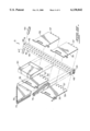
- FIG. 6 illustrates an exploded view of the embodiment shown in FIG. 1 in the wheelbarrow configuration.
- the present invention is generally referred to with numeral 10, it can be observed that it basically includes base assembly 20, elongated tubular assembly 40 with first and second ends 46 and 48 and tray assemblies 30 and 70. These assemblies can be used for a point of sale configuration, as shown in FIG. 1, or in a wheelbarrow configuration as shown in FIG. 2.
- Tray assembly 30 is composed of four triangular (as shown in FIG. 1) or non-triangular (as shown in FIG. 3) tray sections 31; 32; 33 and 34 that define a horizontal surface where goods for display are placed.
- supporting wall assemblies 35 compose a set and are removably mounted to each of the four longitudinal walls 42 of tubular assembly 40, as best seen in FIG. 3.
- Arm assemblies 75 support tray assembly 70.
- Support tray assembly 70 includes tray sections 71, 72, 73, and 74. There may be more tray assemblies like assembly 70. When mounted to tubular assembly 40, supporting wall assemblies 35 of a given set extend outwardly on the same plane.
- Wall assemblies 35 and arm assemblies 75 are positioned in a spaced apart and parallel relationship with respect to each other to keep tray assemblies 30 and 70 also at a spaced apart and parallel relationship with respect to each other.
- Handles 44 and 44', removably attached end to end from one another are in turn removably attached to the first end 46 of tubular assembly 40.
- Top tray assembly 90 is kept at a separate and spaced apart relationship with respect to tray assembly 70. Assembly 90 can be used to support promotional displays. Fastening member 92 keeps assembly 90 mounted to the uppermost end of handle member 44'.
- FIG. 2 illustrates the present invention 10, in the wheelbarrow configuration.
- the user attaches supporting wall assemblies 35 at predetermined locations utilizing lateral hooks 39 removably mounted to longitudinal walls 42 of elongated tubular assembly 40, as best seen in FIG. 6.
- Handles 44 and 44' are secured near the first end 46 and at opposite faces of elongated tubular assembly 40 thread holes 41.
- wheel assembly 24, near the second end 48 of elongated tubular assembly 40 is free to rotate, thus allowing the user to transport the instant invention and its cargo in a wheelbarrow configuration.
- Tubular assembly 40 can also have a non-rectangular cross-section, as shown in FIG. 3a.
- FIG. 3b shows a variation where wall assemblies 35' are hingedly mounted to the corners of longitudinal walls 42. Hinges 36 are positioned in predetermined locations so that wall assemblies 35' cooperate to define a cargo space.
- FIG. 4 depicts a variation of the instant invention when utilized in the point of sale configuration and stationed adjacent to a 270 degree corner.
- FIG. 5 only one tray assembly 70, is utilized for another alternative embodiment in the point of sale configuration being used with a 90 degree corner.
- FIG. 6 depicts an exploded view of the present invention in the wheelbarrow configuration shown in FIG. 2. This view shows the mounting position of the different parts.
- supporting wall assemblies 35 include two sets of hook terminations. One set being the end hooks 37 for perpendicular mounting with respect to longitudinal walls 42. The other set corresponds to the lateral hooks 39 for parallel engagement with walls 42 to configure the wheelbarrow.
Abstract
A point of sale display with a collapsible base assembly removably mounted to one end of an elongated tubular member with a square cross-section. The elongated tubular member includes a lateral wall with slots therealong to receive the ends of supporting walls and arm assemblies that are removably mounted to the longitudinal walls in perpendicular relationship thereto. In one alternative embodiment two of the supporting walls are hingedly mounted, otherwise they include lateral hook terminations. Flat portions are removably mounted on the supporting walls and arm assemblies to provide flat surfaces kept at spaced apart and parallel relationship with respect to each other to support goods in display. In another configuration, the elongated tubular member is used as a wheelbarrow by transferring the weight of the display to the wheel assembly, at one end of the elongated tubular member.
Description
1. Field of the Invention
The present invention relates to point of sale displays, and more particularly, to displays that can be readily dismountable and used as a wheelbarrow.
2. Description of the Related Art
Many designs for point of sale displays have been designed in the past. None of them, however, include a readily dismountable mechanism that converts the display for ready transportation as a wheelbarrow with cargo space capacity. This invention provides a volumetrically efficient solution to the transportation logistics faced by users of point of sale displays, such as salespersons and employees that need to move displays from one location to another. These displays are frequently transported to and from various shows and retail establishments. With the present invention, a user may utilize the display and transport it in a different configuration.
It is one of the main objects of the present invention to provide a point of sale display that can be readily assembled and disassembled.
It is another object of the present invention to provide a display that can be readily converted to a wheelbarrow with cargo capacity.
It is another object of this invention to provide a point of sale display with adjustable shelves.
It is still another object of the present invention to provide a point of sale display that is volumetrically efficient for transportation and storage.
The present invention allows a user to store additional objects on the top tray such as documentation, electrical power supplies or batteries, sensors, lights and other electronic devices, to make the display smart and activate upon the detection of different conditions like the approach of a person (potential customer) and activating audio announcers or lights, or removal of products from the display (for the purposes of refilling or counting inventory), and keeping these devices out of the public's sight.
It is yet another object of this invention to provide such a device that is inexpensive to manufacture and maintain while retaining its effectiveness.
Further objects of the invention will be brought out in the following part of the specification, wherein detailed description is for the purpose of fully disclosing the invention without placing limitations thereon.
With the above and other related objects in view, the invention consists in the details of construction and combination of parts as will be more fully understood from the following description, when read in conjunction with the accompanying drawings in which:
FIG. 1 represents a tilted isometric view of one of the preferred embodiments of the invention in the point of sale display configuration.
FIG. 2 shows a side elevational view of the invention in the wheelbarrow configuration.
FIG. 3 is a tilted isometric view of an alternative embodiment for the present invention wherein the horizontal tray sections have a curved outer edge forming a circular perimeter.
FIG. 3a is a top view of the alternative tubular assembly.
FIG. 3b illustrates an alternative variation of wall assemblies hingedly mounted to the corners of the longitudinal walls.
FIG. 4 is a representation of a top view of another alternative embodiment in the point of sale configuration being used with a 270 degree corner.
FIG. 5 is a representation of a top view of another alternative embodiment in the point of sale configuration being used with a 90 degree corner.
FIG. 6 illustrates an exploded view of the embodiment shown in FIG. 1 in the wheelbarrow configuration.
Referring now to the drawings, where the present invention is generally referred to with numeral 10, it can be observed that it basically includes base assembly 20, elongated tubular assembly 40 with first and second ends 46 and 48 and tray assemblies 30 and 70. These assemblies can be used for a point of sale configuration, as shown in FIG. 1, or in a wheelbarrow configuration as shown in FIG. 2.
Tray assembly 30 is composed of four triangular (as shown in FIG. 1) or non-triangular (as shown in FIG. 3) tray sections 31; 32; 33 and 34 that define a horizontal surface where goods for display are placed. In the preferred embodiment shown in FIG. 1, supporting wall assemblies 35 compose a set and are removably mounted to each of the four longitudinal walls 42 of tubular assembly 40, as best seen in FIG. 3. Arm assemblies 75 support tray assembly 70. Support tray assembly 70 includes tray sections 71, 72, 73, and 74. There may be more tray assemblies like assembly 70. When mounted to tubular assembly 40, supporting wall assemblies 35 of a given set extend outwardly on the same plane. Wall assemblies 35 and arm assemblies 75 are positioned in a spaced apart and parallel relationship with respect to each other to keep tray assemblies 30 and 70 also at a spaced apart and parallel relationship with respect to each other. Handles 44 and 44', removably attached end to end from one another are in turn removably attached to the first end 46 of tubular assembly 40.
Top tray assembly 90 is kept at a separate and spaced apart relationship with respect to tray assembly 70. Assembly 90 can be used to support promotional displays. Fastening member 92 keeps assembly 90 mounted to the uppermost end of handle member 44'.
FIG. 2 illustrates the present invention 10, in the wheelbarrow configuration. The user attaches supporting wall assemblies 35 at predetermined locations utilizing lateral hooks 39 removably mounted to longitudinal walls 42 of elongated tubular assembly 40, as best seen in FIG. 6. Handles 44 and 44' are secured near the first end 46 and at opposite faces of elongated tubular assembly 40 thread holes 41. When tilted towards the user, wheel assembly 24, near the second end 48 of elongated tubular assembly 40, is free to rotate, thus allowing the user to transport the instant invention and its cargo in a wheelbarrow configuration.
Tubular assembly 40 can also have a non-rectangular cross-section, as shown in FIG. 3a. FIG. 3b shows a variation where wall assemblies 35' are hingedly mounted to the corners of longitudinal walls 42. Hinges 36 are positioned in predetermined locations so that wall assemblies 35' cooperate to define a cargo space.
FIG. 4 depicts a variation of the instant invention when utilized in the point of sale configuration and stationed adjacent to a 270 degree corner. In FIG. 5, only one tray assembly 70, is utilized for another alternative embodiment in the point of sale configuration being used with a 90 degree corner.
FIG. 6 depicts an exploded view of the present invention in the wheelbarrow configuration shown in FIG. 2. This view shows the mounting position of the different parts. As it can be seen, supporting wall assemblies 35 include two sets of hook terminations. One set being the end hooks 37 for perpendicular mounting with respect to longitudinal walls 42. The other set corresponds to the lateral hooks 39 for parallel engagement with walls 42 to configure the wheelbarrow.
The foregoing description conveys the best understanding of the objectives and advantages of the present invention. Different embodiments may be made of the inventive concept of this invention. It is to be understood that all matter disclosed herein is to be interpreted merely as illustrative, and not in a limiting sense.
Claims (3)
1. A point of sale display, comprising:
A) an elongated tubular member having first and second ends, and a lateral wall, said lateral wall including a plurality of slots, said first end including a wheel assembly extending perpendicularly outwardly from said lateral wall and a flange member on said lateral wall opposite to said wheel assembly;
B) a base assembly having at least two supporting walls including means for removably and perpendicularly mounting said supporting walls to said elongated tubular member adjacent to said first end, said supporting walls being cooperatively disposed to support a flat portion, and said supporting walls further including means for removably mounting said supporting walls in parallel relationship with respect to said elongated tubular member so that in a wheelbarrow configuration said supporting walls can be mounted with at least one pair of said supporting walls in parallel and spaced relationship with respect to each other thereby defining a space in between for storage, and further including latch means for keeping said two supporting walls in place and providing, in cooperation with said flange member, two resting surfaces; and
C) a first tray assembly perpendicularly and removably mounted to said elongated tubular member at a predetermined position, said tray assembly including at least one flat portion removably mounted to said elongated tubular member and being supported by said supporting walls.
2. The display set forth in claim 1 further including:
D) at least one second tray assembly perpendicularly and removably mounted to said elongated tubular member at a predetermined position, said tray assembly including at least one flat portion removably mounted to said elongated tubular member; and
E) at least one arm means for supporting said second tray assembly being removably mounted to said lateral wall.
3. The display set forth in claim 2 wherein two supporting walls are hingedly mounted to said lateral wall so that in the wheelbarrow configuration said hingedly mounted supporting walls are kept in a parallel and spaced apart relationship in respect to each other.
Priority Applications (3)
| Application Number | Priority Date | Filing Date | Title |
|---|---|---|---|
| US09/502,657 US6138842A (en) | 2000-02-11 | 2000-02-11 | Point of sale display |
| AU2000238612A AU2000238612A1 (en) | 2000-02-11 | 2000-02-25 | Point of sale display |
| PCT/US2000/005077 WO2001058318A1 (en) | 2000-02-11 | 2000-02-25 | Point of sale display |
Applications Claiming Priority (1)
| Application Number | Priority Date | Filing Date | Title |
|---|---|---|---|
| US09/502,657 US6138842A (en) | 2000-02-11 | 2000-02-11 | Point of sale display |
Publications (1)
| Publication Number | Publication Date |
|---|---|
| US6138842A true US6138842A (en) | 2000-10-31 |
Family
ID=23998790
Family Applications (1)
| Application Number | Title | Priority Date | Filing Date |
|---|---|---|---|
| US09/502,657 Expired - Lifetime US6138842A (en) | 2000-02-11 | 2000-02-11 | Point of sale display |
Country Status (3)
| Country | Link |
|---|---|
| US (1) | US6138842A (en) |
| AU (1) | AU2000238612A1 (en) |
| WO (1) | WO2001058318A1 (en) |
Cited By (10)
| Publication number | Priority date | Publication date | Assignee | Title |
|---|---|---|---|---|
| US6766914B1 (en) | 2003-06-09 | 2004-07-27 | Ciro Rios | Multiple configuration display |
| US20080169253A1 (en) * | 2007-01-16 | 2008-07-17 | 4 Smart People, Inc. | Apparatus for organizing and storing sports equipment |
| US20090063166A1 (en) * | 2004-07-20 | 2009-03-05 | Food Cap International Limited | Product Distribution Methods and Apparatus |
| US20090223907A1 (en) * | 2008-03-07 | 2009-09-10 | Wal-Mart Stores, Inc. | Merchandise Display Unit |
| US20100059404A1 (en) * | 2008-09-05 | 2010-03-11 | Menelaos Tzilvelis | Tray space saver |
| US20110135807A1 (en) * | 2001-05-10 | 2011-06-09 | Johann Kappacher | Multi-layer, substantially polyvinyl chloride- and polyolefin-free composite film |
| US20110186530A1 (en) * | 2008-03-07 | 2011-08-04 | Wal-Mart Stores, Inc. | Device Display Unit |
| US9492020B1 (en) * | 2015-07-17 | 2016-11-15 | Chicago Display Company | Display rack |
| US9782020B2 (en) * | 2016-02-22 | 2017-10-10 | Stephen H Bacon | Merchandise display shelving unit |
| US11122916B2 (en) * | 2019-10-23 | 2021-09-21 | Quenetics, LLC | Adjustable rotating assembly |
Families Citing this family (1)
| Publication number | Priority date | Publication date | Assignee | Title |
|---|---|---|---|---|
| DE102012022407A1 (en) * | 2012-11-16 | 2014-05-22 | Casimir Kast Verpackung und Display GmbH | Shelf for presentation of goods, has base part and freely projecting support part extending vertically upwards from base part, where plate-like goods carrier, which freely projects to multiple sides of support part, is held in support part |
Citations (2)
| Publication number | Priority date | Publication date | Assignee | Title |
|---|---|---|---|---|
| US3771665A (en) * | 1972-02-29 | 1973-11-13 | Raymond Lee Organization Inc | Portable pot stand |
| US5660404A (en) * | 1994-10-13 | 1997-08-26 | Bell Packaging Corporation | Mobile display base assembly |
Family Cites Families (2)
| Publication number | Priority date | Publication date | Assignee | Title |
|---|---|---|---|---|
| US4262439A (en) * | 1979-05-21 | 1981-04-21 | Dinaco, Inc. | Display stand |
| US5906284A (en) * | 1997-11-18 | 1999-05-25 | Kenneth Hammerstrom | Multi-workstation device |
-
2000
- 2000-02-11 US US09/502,657 patent/US6138842A/en not_active Expired - Lifetime
- 2000-02-25 WO PCT/US2000/005077 patent/WO2001058318A1/en active Application Filing
- 2000-02-25 AU AU2000238612A patent/AU2000238612A1/en not_active Abandoned
Patent Citations (2)
| Publication number | Priority date | Publication date | Assignee | Title |
|---|---|---|---|---|
| US3771665A (en) * | 1972-02-29 | 1973-11-13 | Raymond Lee Organization Inc | Portable pot stand |
| US5660404A (en) * | 1994-10-13 | 1997-08-26 | Bell Packaging Corporation | Mobile display base assembly |
Cited By (12)
| Publication number | Priority date | Publication date | Assignee | Title |
|---|---|---|---|---|
| US20110135807A1 (en) * | 2001-05-10 | 2011-06-09 | Johann Kappacher | Multi-layer, substantially polyvinyl chloride- and polyolefin-free composite film |
| US6766914B1 (en) | 2003-06-09 | 2004-07-27 | Ciro Rios | Multiple configuration display |
| US20090063166A1 (en) * | 2004-07-20 | 2009-03-05 | Food Cap International Limited | Product Distribution Methods and Apparatus |
| US9950835B2 (en) * | 2004-07-20 | 2018-04-24 | Foodcap International Limited | Product distribution methods and apparatus |
| US20080169253A1 (en) * | 2007-01-16 | 2008-07-17 | 4 Smart People, Inc. | Apparatus for organizing and storing sports equipment |
| US8020716B2 (en) * | 2007-01-16 | 2011-09-20 | 4 Smart People, Inc. | Apparatus for organizing and storing sports equipment |
| US20090223907A1 (en) * | 2008-03-07 | 2009-09-10 | Wal-Mart Stores, Inc. | Merchandise Display Unit |
| US20110186530A1 (en) * | 2008-03-07 | 2011-08-04 | Wal-Mart Stores, Inc. | Device Display Unit |
| US20100059404A1 (en) * | 2008-09-05 | 2010-03-11 | Menelaos Tzilvelis | Tray space saver |
| US9492020B1 (en) * | 2015-07-17 | 2016-11-15 | Chicago Display Company | Display rack |
| US9782020B2 (en) * | 2016-02-22 | 2017-10-10 | Stephen H Bacon | Merchandise display shelving unit |
| US11122916B2 (en) * | 2019-10-23 | 2021-09-21 | Quenetics, LLC | Adjustable rotating assembly |
Also Published As
| Publication number | Publication date |
|---|---|
| AU2000238612A1 (en) | 2001-08-20 |
| WO2001058318A1 (en) | 2001-08-16 |
Similar Documents
| Publication | Publication Date | Title |
|---|---|---|
| CA2441221C (en) | Conversion tower display system | |
| US6460950B2 (en) | Modular container/bookshelf moving cart | |
| US6138842A (en) | Point of sale display | |
| US8016135B2 (en) | Product display support systems and methods | |
| US4819899A (en) | Merchandising rack | |
| US4747644A (en) | Portable display stand | |
| US3538863A (en) | Rotatable display,storage and merchandise distribution cabinet | |
| US7448634B1 (en) | Collapsible display rack | |
| US4487134A (en) | Portable worktable | |
| US7204372B2 (en) | Rug display system | |
| US5779067A (en) | Vertical refrigerator side rack and method | |
| US6609693B2 (en) | Hanger combination for displaying merchandise | |
| US20180213946A1 (en) | An anti-theft storage and display assembly | |
| JPH11196984A (en) | Exhibition shelf for exhibiting commodity storage boxes | |
| US7624880B2 (en) | Rug display system | |
| US7134735B2 (en) | Security shelf display case | |
| US6186607B1 (en) | Display and storage unit | |
| KR20050021636A (en) | Display stand | |
| US6766914B1 (en) | Multiple configuration display | |
| US10213031B2 (en) | Pillow display stand and assembly | |
| US20030193005A1 (en) | Hanger combination for displaying merchandise | |
| US10359232B2 (en) | Bag drying apparatus | |
| KR101957293B1 (en) | Goods Shelves | |
| JP3083872U (en) | Work cart | |
| JPH0538309A (en) | Goods display device |
Legal Events
| Date | Code | Title | Description |
|---|---|---|---|
| AS | Assignment |
Owner name: CRR BIOMEDICAL, INC., FLORIDA Free format text: ASSIGNMENT OF ASSIGNORS INTEREST;ASSIGNOR:RIOS, CIRO;REEL/FRAME:010615/0389 Effective date: 20000225 |
|
| STCF | Information on status: patent grant |
Free format text: PATENTED CASE |
|
| FPAY | Fee payment |
Year of fee payment: 4 |
|
| FPAY | Fee payment |
Year of fee payment: 8 |
|
| FPAY | Fee payment |
Year of fee payment: 12 |