US6138388A - Plug system for a snowplow - Google Patents
Plug system for a snowplow Download PDFInfo
- Publication number
- US6138388A US6138388A US09/510,048 US51004800A US6138388A US 6138388 A US6138388 A US 6138388A US 51004800 A US51004800 A US 51004800A US 6138388 A US6138388 A US 6138388A
- Authority
- US
- United States
- Prior art keywords
- housing
- connector
- interface
- electrical connection
- electrical
- Prior art date
- Legal status (The legal status is an assumption and is not a legal conclusion. Google has not performed a legal analysis and makes no representation as to the accuracy of the status listed.)
- Expired - Lifetime
Links
Images

Classifications
-
- E—FIXED CONSTRUCTIONS
- E01—CONSTRUCTION OF ROADS, RAILWAYS, OR BRIDGES
- E01H—STREET CLEANING; CLEANING OF PERMANENT WAYS; CLEANING BEACHES; DISPERSING OR PREVENTING FOG IN GENERAL CLEANING STREET OR RAILWAY FURNITURE OR TUNNEL WALLS
- E01H5/00—Removing snow or ice from roads or like surfaces; Grading or roughening snow or ice
- E01H5/04—Apparatus propelled by animal or engine power; Apparatus propelled by hand with driven dislodging or conveying levelling elements, conveying pneumatically for the dislodged material
- E01H5/06—Apparatus propelled by animal or engine power; Apparatus propelled by hand with driven dislodging or conveying levelling elements, conveying pneumatically for the dislodged material dislodging essentially by non-driven elements, e.g. scraper blades, snow-plough blades, scoop blades
-
- B—PERFORMING OPERATIONS; TRANSPORTING
- B60—VEHICLES IN GENERAL
- B60Q—ARRANGEMENT OF SIGNALLING OR LIGHTING DEVICES, THE MOUNTING OR SUPPORTING THEREOF OR CIRCUITS THEREFOR, FOR VEHICLES IN GENERAL
- B60Q2800/00—Features related to particular types of vehicles not otherwise provided for
- B60Q2800/20—Utility vehicles, e.g. for agriculture, construction work
Definitions
- the present invention relates to the art of snowplows for automotive vehicles and, more particularly, to the wiring and connection arrangement for connecting the solenoid of the lift unit and/or auxiliary lights for the snowplowing system.
- the present invention finds particular utility in connection with vehicles having an attachable and detachable snowplow blade unit and, accordingly, is disclosed and described in detail hereinafter in connection with such use.
- the snowplow blade is mounted on the front of a vehicle such as a car, truck, or the like, together with one or more hydraulic cylinders by which the blade is elevated and lowered relative to the vehicle and the underlying ground and by which the blade is angled to the left or right relative to the vehicle and ground.
- the snowplow blade unit includes one or more solenoids that operate valves by which the flow of hydraulic fluid to and from the hydraulic cylinders is controlled to achieve the various positioning functions of the snowplow blade.
- Selective positioning of the snowplow blade through the control of the solenoid valves and an electric motor driven hydraulic pump is achieved through a control device mounted in the cab of the vehicle such as on the dashboard thereof for operation by the vehicle operator.
- a control device mounted in the cab of the vehicle such as on the dashboard thereof for operation by the vehicle operator.
- an electrical cord of sheathed conductors extends from the control device in the cab of the vehicle to the operating components of the system.
- Auxiliary lights are used in combination with the snowplow lift unit to enable an operator to operate the snowplow during evening hours.
- the snowplow blade unit are typically mounted to the front of the vehicle. As a result, the snowplow blade unit blocks the light generated by the headlights of the vehicle.
- the auxiliary lights are commonly mounted on the snowplow blade unit and/or positioned on the vehicle so as to provide illumination to a road surface during the operation of the snowplow.
- the auxiliary lights and the one or more solenoids for the lift unit use separate wiring arrangements to operate the solenoids and the auxiliary lights.
- the solenoid is connected to several wires which causes the solenoid to operate the lift unit which in turn lifts and lowers the snowplow and/or moves the snowplow from side to side. These wires from the solenoid are fed through the grill of the vehicle, through the engine compartment and fire wall, and into the passenger compartment of the vehicle where the wires are connected to a controller.
- the lift unit is connected to one or more power cables to energize the electric motors in the lift unit.
- auxiliary lights also include electric connections.
- a typical wiring arrangement for the auxiliary lights is shown in U.S. patent application Ser. No. 09/159,035 filed Sep. 23, 1998 entitled “Light Harness” and U.S. Pat. No. 4,280,062.
- Each auxiliary light is connected a set of wires that lead from the auxiliary light, through the grill of the vehicle and into the engine compartment. As a result, at least four sets of wires are routed through the grill when the lift unit and auxiliary lights are connected to the vehicle.
- the number of wires needed to operate the lift unit of the snowplow and the auxiliary lights makes it difficult and inconvenient to disconnect and reconnect the snowplow blade unit and/or auxiliary lights from the vehicle. Furthermore, the wires for the lift unit and the auxiliary lights must be properly connected together or possible damage to the components may occur and/or the components will not operate properly. In addition, when the various wires are disconnected from the auxiliary lights and/or lift unit, the wire ends are left to dangle in the front of the vehicle. As a result, the operator must repeatedly pull the wires through the grill and somehow secure the lose wires in the engine compartment or risk damage to the dangling wires. Due to the complexity and/or inconvenience in the wiring of the auxiliary lights and lift unit, the snowplow blade unit and auxiliary lights typically remain on the vehicle throughout the winter months even though the snowplow blade unit can be easily detached and reattached to the vehicle.
- the present invention is an improvement for attaching a snowplow blade unit to a vehicle which overcomes all of the above referred problems and enables a lift mount assembly and/or a blade mount assembly to be quickly released from the vehicle.
- the snowplow blade unit includes a frame mount assembly, a lift assembly, and a blade mount assembly.
- the lift assembly and/or blade mount assembly are designed to be detachable and reattachable to the frame mount assembly.
- the frame mount assembly is structurally simple and light in weight, thus facilitating the installation of the frame mount and reducing the weight imposed on the front axle of the vehicle.
- the frame mount assembly is structurally independent of the vehicle bumper and is mountable on a vehicle without replacing the original or existing bumper.
- the frame mount assembly enables quick release and removal of the lift assembly and the blade mount assembly from the frame mount assembly, thus resulting in only the frame mount assembly remaining on the vehicle.
- the frame mount assembly is mounted on the vehicle to minimize both the visibility of the frame mount assembly and the projection of the parts of the frame mount assembly thereof forwardly of the vehicle.
- a support assembly is designed to be connected to the frame mount assembly.
- the support assembly is also design to be connected to the lift assembly unit and/or the blade mount assembly.
- the support assembly and lift assembly are integrated together.
- the lift assembly includes a lift arm that is connected or interconnected to the blade mount assembly for lifting and lowering the blade mount assembly.
- the lift mount assembly includes a power mechanism to lift and lower the lift arm.
- the power mechanism includes a solenoid.
- the solenoid is designed to directly move the lift arm and/or control an electrical or hydraulic device which in turn directly moves the lift arm.
- the solenoid includes a plurality of valves to control the flow of pressurized hydraulic fluid to a ram to lift the snowplow blade and/or to angle the snowplow blade. The solenoid is generally remotely controlled by an operator.
- the blade mount assembly includes an A-frame design to support a snowplow blade.
- the blade mount includes two pistons which move the snowplow blade from side to side.
- the pistons are generally electrically and/or hydraulically powered.
- the solenoids of the lift unit directly move the pistons and/or control an electrical or hydraulic device which in turn directly moves the pistons.
- one or more auxiliary lights are used in conjunction with the snowplow blade unit.
- one or more auxiliary lights are mounted to the snowplow blade unit.
- an electrical connector is provided to electrically connect one or more components of a snowplow blade unit and/or auxiliary lights to a power source and/or controller located in the vehicle. The electrical connector is design to simply the electrical connections between the electrical components located on the exterior of the vehicle and the electrical connections located in the vehicle.
- the frame mount assembly is design to include a connection section that facilitates in the attachment of the support assembly and/or a structural support for one or more components of the snowplow blade unit and to help rigidify and strengthen such components.
- the frame mount assembly includes one or more regions that at least partially assist in guiding at least a portion of the support assembly into proper orientation with the frame mount assembly so that the support assembly can be mounted to the frame mount assembly.
- the support assembly includes one or more connectors to enable the support assembly to be easily removed and/or attached to the frame mount assembly.
- the lift mount assembly includes an adjustable lift arm.
- the height of the lift arm can be adjusted so as to accommodate a variety of different vehicles and/or increase the efficiency and operation of the lift mount assembly.
- a plurality of connection locations are positioned on the legs of the lift mount assembly.
- the lift arm is connected in a singular angular orientation with respect to the legs.
- the lift arm is connected to enable a plurality of angular orientations with respect to the legs.
- the blade mount assembly includes a support mechanism to elevate at least a portion of the blade assembly above a ground surface when the blade mount assembly is detached from the support assembly and/or the support assembly is detached from the frame mount assembly.
- the support leg enables an operator to conveniently attach and/or reattach the end of the blade mount assembly to the support assembly, and/or helps to prevent damage to the support assembly and/or the blade mount assembly during the connecting and/or reconnecting of the blade mount assembly to the support assembly.
- a snowplow mount arrangement wherein the blade mount assembly and/or the lift mount assembly can be easily connected and/or disconnected from the vehicle.
- the simple removal of one or two bolts or pins disengages the blade mount assembly.
- the simple removal of a few bolts or pins results in the detachment of both the blade mount assembly and the lift mount assembly from the frame mount assembly.
- the components of the lift mount assembly and blade mount assembly can be oriented so that when the components are completely removed from the frame mount assembly, they can be easily stored for later use and reattachment.
- the auxiliary lights are energized by an auxiliary light harness.
- the auxiliary light harness incorporates a simple modular design that simplifies the installation of the auxiliary light harness which reduces installation errors, and improves the safety and reliability of the auxiliary multiplex light harness.
- the auxiliary light harness includes electrical connectors designed to connect to the OEM wiring of the vehicle headlights and to the OEM wiring for the power source of the vehicle headlights.
- the vehicle headlights include a connector which connects to the power source of a vehicle.
- the auxiliary light harness includes connectors whereby one of the connectors is connected to the vehicle headlight or headlight wiring and anther connector is connected to the power source to which the vehicle headlight was originally attached.
- the auxiliary light harness design utilizes all of the OEM wiring of a vehicle, thus none of the OEM wiring of the vehicle is discarded or only partially utilized when the auxiliary light harness is attached to the vehicle.
- the auxiliary light harness is integrated with the turning signals and/or emergency lighting of the vehicle.
- the auxiliary headlights include turn signals and/or emergency lighting so that such turning signals and/or emergency lights are activated when the operator of the vehicle activates the turning signals and/or emergency lights.
- the auxiliary light harness includes solid state circuitry which controls the activation and deactivation of the auxiliary lights, and/or the intensity of the light from the auxiliary lights.
- the solid state circuitry increases the reliability of the auxiliary multiplex light harness circuitry and reduces the number of wires needed to connect the auxiliary multiplex light harness to the OEM wiring of the vehicle.
- the auxiliary light harness is designed to be a modular unit which allows the auxiliary lights to be easily detached and removed from the vehicle without having to dismantle and remove the complete auxiliary multiplex light harness from the vehicle.
- the auxiliary light harness is connected to the vehicle power source to reduce the occurrences of the auxiliary lights draining the power of the vehicle's battery.
- the auxiliary light harness is connected to the ignition mechanism of the vehicle such that the ignition switch must be activated prior to the auxiliary lights being activated.
- the auxiliary light harness is designed to enable the vehicle's headlights or the auxiliary lights of the vehicle to be activated; or allow both the auxiliary lights and the headlights of the vehicle to be activated.
- the auxiliary light harness includes and/or incorporates circuitry to operate the auxiliary lights for daytime running.
- the auxiliary light harness is integrated with the high and low beam switch for the vehicle headlights so that the same switch can be used to control the beam mode of the auxiliary lights when the auxiliary lights are activated.
- the beam mode of the auxiliary lights is automatically controlled.
- the auxiliary light harness receives a signal from a light sensor to enable activate the auxiliary lights during day light hours.
- the auxiliary light harness circuitry alters the intensity of light produces by the auxiliary lights.
- the auxiliary light harness reduces the intensity of the auxiliary lights to produces a light intensity that is less than the light intensity at low beam mode.
- the auxiliary light harness includes a processing module to control the operation of the auxiliary lights.
- the processing module is designed to receive signals from various components on and/or in the vehicle and control the operation of the auxiliary lights based upon such received information.
- the processing module controls the operation of one or more auxiliary lights.
- the processing module controls the operation of one or more auxiliary lights and one or more vehicle lights.
- the processing module controls the operation of one or more auxiliary lights, one or more vehicle headlights, one or more vehicle turn signals, one or more vehicle parking lamps, one or more vehicle daylight running lamps, and/or vehicle emergency lights.
- the auxiliary light harness uses and/or generates analog and/or digital signals to control one or more components on the vehicle.
- the analog/digital signals enable the processing module to receive and/or send distinct signals that can be easily verified and/or interpreted so as to minimize errors during operation.
- the processing module is designed to send and/or receive verification signals and/or have some other protocol to verify the signals received and/or sent, and/or to verify whether the instructions were properly receive and/or sent.
- the auxiliary light harness incorporates a device to convert signals into a different form for transmission through the circuitry of the auxiliary multiplex light harness.
- the auxiliary light harness includes a remote switch to active and/or deactivate one or more components of the auxiliary light harness.
- the remote switch generates a coded radio frequency, when activated by an operator, which coded frequency is received by the processing module that in turn causes the processing module to activate and/or deactivate one or more components of the auxiliary multiplex light harness and/or to cause the processing module to generate and/or terminate the generation of signals.
- the remote switch activates one or more functions of the auxiliary multiplex light harness.
- the auxiliary lights include a light controller that controls the operation of the auxiliary light components.
- the light controller is designed to control one or more modes of the auxiliary light such as, but not limited to, the low beam mode, the high beam mode, the daylight running mode, the on mode, the off mode, the turning light mode, the emergency light mode, and/or the test sequence mode.
- the light controller is designed to receive and/or transmit analog/digital signals from and/or to the processing module.
- the auxiliary light harness incorporates special connectors to ensure that the connectors will not inadvertently become disconnected during operation.
- the connectors include a lock system such as a snap lock, which ensures that the connectors are properly secured together and to further prevent the connections from loosening or becoming disconnected during the operation of the vehicle.
- the connectors are designed to allow the connectors to be connected in only one manner, so as to prevent an improper connection. In this manner, the connectors are specially shaped so that the connectors can only be attached together in one manner.
- the connectors include a seal arrangement to prevent foreign materials from damaging and/or causing a short in the circuitry of the auxiliary light harness.
- the connectors include rubber, plastic, and/or Teflon seals to prevent foreign materials from interacting with the electrical connections of the vehicle light harness.
- the seals help prevent corrosion of the electrical connections, bad connections between the electrical connections, shorting of the electrical connections and the like.
- the connectors include plugs which are utilized when the auxiliary lights are disconnected and removed from the vehicle. The connector plugs are designed to connect to the ends of these electrical connections to seal the electrical connections from the environment, thereby inhibiting and/or preventing corrosion of the electrical connections, and/or other debris from depositing on the electrical connections which may impair the operation of the auxiliary multiplex light harness when the auxiliary lights are once again attached to the harness.
- the snowplow blade unit and/or auxiliary light system includes a simplified connector arrangement which facilitates in easily and reliably connecting and/or disconnecting one or more of the components of the snowplow blade unit and/or the auxiliary lights from the exterior of the vehicle.
- an external electrical connector is used to provide an electrical connection to one or more components of a snowplow blade unit that are positioned externally of the vehicle.
- an external electrical connector is used to provide an electrical connection to one or more auxiliary lights that are positioned externally of the vehicle.
- an external electrical connector is used to provide an electrical connection to one or more auxiliary lights and to one or more components of a snowplow blade unit that are positioned externally of the vehicle.
- the connector arrangement reduces the number of electrical connections that must to disconnected and reconnected when one or more components of a snowplow blade unit and/or the auxiliary lights are detached and reattached to the vehicle.
- the connection arrangement includes an external electrical connector that has a plurality of housings.
- the housings are designed to be connected together to form electrical connections between the housings.
- the external electrical connector has first and second housing components that can be secured together.
- Each housing component includes an interface end and a coupling end.
- the coupling ends of the two housing components are designed to be connect together to form an electrical connection between the two housings.
- the interface ends of the two housings include at least one electrical connection interface that is designed to form an electrical connection with one or more components of a snowplow blade unit and/or the auxiliary lights.
- the electrical connection interface is designed to form an electrical connection with an auxiliary light, a lift unit solenoid and/or a snowplow blade positioning solenoid.
- the housings are made of a durable, corrosion resistant material to protect the internal component of the housing.
- the housings include a hard plastic material.
- external electrical connector includes housings having interface ends and coupling ends and wherein the number of electrical connection interfaces on the interface ends is different from the number of electrical connection interfaces on the coupling ends. In one embodiment, the number of electrical connection interfaces on the interface ends is greater than the number of electrical connection interfaces on the coupling ends.
- the reduced number of electrical connection interfaces on said coupling ends further simplifies the manner in which the housings can be connected together. Furthermore, the reduced number of electrical connection interfaces minimizes the complexity of the housings and reduces the chances of damaging the electrical connection interfaces when the housings are repeatedly connected and disconnected.
- the electrical connection interfaces on the interface ends of the housings are designed to form an electrical connection with an electrical cable that supplies power to an auxiliary light and/or transmits information between an auxiliary light and the auxiliary light harness.
- the cable that provides an electrical connection to the auxiliary light is disconnected from the auxiliary light and connected to one electrical connection interfaces on the interface end of one housing.
- Another cable for the auxiliary light is provided wherein one end of the cable is connected to one electrical connection interfaces on the interface end of another housing and the other end of the cable is connected to the auxiliary light.
- the electrical connection interfaces on the interface ends of the housings are designed to form an electrical connection with an electrical cable that supplies power to a solenoid and/or transmits information between a solenoid and the solenoid controller.
- the one or more cables that provides an electrical connection to the solenoid is disconnected from the solenoid and connected to one electrical connection interfaces on the interface end of one housing.
- Another cable or set of cables for the solenoid is provided wherein one end of the one or more cables is connected to one electrical connection interfaces on the interface end of another housing and the other end of the one or more cables is connected to the solenoid.
- At least a majority of the snowplow blade unit components that transmit and/or receive electrical signals and the auxiliary lights used in conjunction with the snowplow blade unit are connected to the housings of the external electrical connector.
- most or all of the electrical connections of the snowplow blade unit and the auxiliary lights are routed a single external electrical connector.
- the external electrical connector reduces the number of electrical connections that must be disconnected and reconnected when the auxiliary lights and components of the snowplow blade unit are disconnected and reconnected to the vehicle. The reduced number of connections simplifies and reduces the time required to disconnect and reconnect the auxiliary lights and components of the snowplow blade unit to the vehicle.
- At least one housing of the external electrical connector includes a attachment arrangement to secure the housing to a component of the snowplow blade unit.
- the housing is connected to a component of the snowplow blade unit that is detachable and reattachable to the vehicle.
- the housing is connected to the lift assembly and/or the blade mount assembly.
- the attachment arrangement on one of the housings includes a clip, slot, opening of the like.
- the housing includes at least one opening to receive a pin, bolt, screw or the like to secure the housing to the snowplow blade unit.
- the housing is releasably secured to the snowplow blade unit.
- the housing is removable for ease of repair, maintenance, replace or the like.
- a cotter pin arrangement, a spring clip or pin arrangement and the like are used to releasably secure the housing to the snowplow blade unit.
- At least one housing of the external electrical connector is designed to receive a protection cap that protects the electrical connection interfaces on the coupling end and/or interface end of the housing.
- the protection cap is designed to inhibit or prevent dirt, moisture of the like from contacting the exposed ends of the electrical connection interfaces thereby reducing the damage to the electrical connection interfaces.
- the protection cap is also designed to protect the exposed ends of the electrical connection interfaces from damage resulting from contact with other objects.
- the protection cap is connected to the coupling end of the housing when the housing is disconnected from another housing.
- the protection cap is releasably secured to the housing so that the protection cap can be removed to allow an electrical connection interfaces to be used.
- the protection cap includes a clip, slot, groove, rib or the like to releasably secure the protection cap to the housing.
- the housing includes a clip, slot, groove, rib or the like to releasably secure the protection cap to the housing.
- the coupling end and/or interface end of the housing includes a sealing arrangement to form a seal with one or more electrical connection interfaces when an electrical connection is made with the one or more electrical connection interfaces.
- the sealing arrangement is designed to inhibit or prevent dirt, moisture of the like from interfering with the electrical connection that is formed with the electrical connection interfaces.
- the sealing arrangement includes a flexible seal.
- the flexible seal at least partially surrounding an outer surface of the electrical connection interface.
- the flexible seal includes at least one corrugation.
- the sealing arrangement includes a locking arrangement to secure an electrical connector to an electrical connection interface.
- the locking arrangement assists in ensuring that a proper electrical connection is formed with the electrical connection interface and/or that the electrical connection does not inadvertently disconnect.
- the locking arrangement forms a releasably connection between an electrical connector to an electrical connection interface.
- the locking arrangement includes a locking tab to form the releasable connection.
- a housing holder is provided for one of the housings.
- the housing holder is designed to secure one or more of the housings of the connection arrangement to the vehicle.
- the housing holder is designed to protect the electrical connection interfaces on the coupling end and/or interface end of the housing.
- the housing holder is also designed to inhibit or prevent dirt, moisture of the like from contacting the exposed ends of the electrical connection interfaces thereby reducing the damage to the electrical connection interfaces.
- the housing holder is further designed to protect the exposed ends of the electrical connection interfaces from damage resulting from contact with other objects.
- the housing holder is secured to the grill of the vehicle.
- the housing holder includes a fastener that enables the housing holder to be releasably secured to the grill of the vehicle.
- the housing holder secures the housing in position when the housing is disconnected from another housing.
- one of the housings is connected to one or more electrical connectors emanating from the interior of the vehicle, such as, but not limited to the engine compartment.
- the plurality of electrical connections can be bundled together to facilitate in there ease of handling.
- the housing that is connected to these electrical connections is disconnected from another housing, the housing dangles loosely in front of the vehicle.
- the housing holder is designed to secure this housing in position to reduce damage to the housing and/or the electrical connections.
- the housing holder is releasably secured to the housing so that the housing can be removed from the holder and connected to another housing.
- the housing holder completely encloses the housing when the housing is inserted into the housing holder.
- the housing holder partially encloses the housing when the housing is inserted into the housing holder.
- the housing holder includes a clip, slot, groove, rib or the like to releasably secure the housing in the housing holder.
- the housing includes a clip, slot, groove, rib or the like to releasably secure the housing in the housing holder.
- Another object of the present inventions is the provision of a snowplow blade unit and/or auxiliary light assembly which enables quick release and/or removal of the components of the snowplow blade unit and/or auxiliary lights from the vehicle.
- Another object of the present invention is the provision of a snowplow blade unit and/or auxiliary light assembly which enables the operator to easily connect and/or disconnect various components of the snowplow blade unit and/or auxiliary light assembly from the vehicle.
- a further object of the present invention is the provision of a snowplow blade unit which enables the attachment and/or detachment of the lift mount assembly, support assembly and/or blade mount assembly in a safe, sufficient, and/or convenient manner.
- It is still yet another object of the present invention is the provision of providing improvements in a snowplow blade unit mountable on a vehicle for elevating and/or lowering the plow blade.
- Another object of the present invention is the provision of a snowplow blade unit and/or auxiliary light assembly which enables quick and easy detachment of the support assembly from the frame mount assembly and the auxiliary lights during periods of non-snowplow use of the vehicle.
- Still yet another object of the present invention is the provision of an auxiliary light harness that can be used in conjunction with a vehicle and which is simple to install and operate.
- Still another object of the present invention is the provision of an auxiliary light harness which utilizes the OEM wiring of a vehicle headlight system without the need to splice the OEM wiring to the vehicle headlights.
- Another object of the present invention is the provision of an auxiliary light harness which operates the auxiliary lights for daytime lighting.
- Still another object of the present invention is the provision of an auxiliary light harness which reduces the intensity of the light from the auxiliary lights during daytime running.
- Still another object of the present invention is the provision of an auxiliary light harness that includes a processing module to control the operation of the components of the light harness.
- Still yet another object of the present invention is the provision of an auxiliary light harness that incorporates a light controller in the auxiliary lights.
- Still another object of the present invention is the provision of an auxiliary light harness which allows for one or more of the components of the harness to be easily attached and reattached to the vehicle without having to substantially remove the harness from the vehicle.
- Yet another object of the present invention is the provision of an auxiliary light harness which can be easily maintained and repaired.
- Another object of the present invention is the provision of an auxiliary light harness that includes a sealing arrangement to reduce degradation of the electrical circuitry and/or interface with electrical connections.
- a further object of the present invention is the provision of an electrical connector that easily and conveniently connects and disconnects a plurality of different electrical connections.
- Still a further object of the present invention is the provision of an electrical connector that protects the electrical connections formed with the electrical connections.
- Yet a further object of the present invention is the provision of an electrical connector that has a plurality of component and one of the components is connectable to a part of a snowplow blade unit.
- Still another object of the present invention is the provision of a control device mounted in the cab of a vehicle for positionally controlling a snowplow blade mounted on the front end of the vehicle.
- Yet another object of the present invention is the provision of a control device which optimize a vehicle operator's convenience with respect to operating the control device to achieve blade positioning.
- Still yet another object of the present invention is the provision of a control device which provides the operator selectivity with respect to positioning the control device in the cab area in a location most suitable to the operator.
- a further object of the present invention is the provision of a control device having a readily separable fastener component which is mounted on the control device.
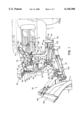
- FIG. 1 is a side perspective view of a snowplow blade unit and auxiliary light which electrical connections are connected to the connection arrangement in accordance with the present invention
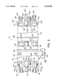
- FIG. 2 is a side view of the connection arrangement wherein the two components of the connection arrangement are secured together;
- FIG. 3 is a side view of the connection arrangement wherein the two components of the connection arrangement are disconnected from one another;
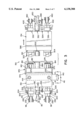
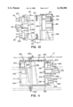
- FIGS. 4-6 are the side and end views of one component of the connection arrangement
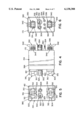
- FIGS. 7-9 are the side and end views of the other component of the connection arrangement
- FIG. 10 is a side view of one of the components of the connection arrangement having a protective cap releasably secured to an end of the component;
- FIG. 11 is a side view of one of the components of the connection arrangement releasably secured to a housing holder that is secured to the grill of a vehicle;
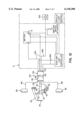
- FIG. 12 is a schematic illustration of the connection of the hydraulic and electrical system for controlling the position of the snowplow blade through a control device and the connection of the electrical system for the auxiliary lights according to the present invention.
- FIG. 1 discloses a snowplow quick mount lift assembly which is similar to the assembly disclosed in U.S. Pat. No. 5,036,608 which is incorporated herein by reference.
- vehicle V includes a snowplow blade unit 20 attached to the front of the vehicle.
- Snowplow blade unit 20 includes a housing mount unit 30 secured to the bottom frame of vehicle V.
- housing mount unit 30 is secured to the bottom of the vehicle so that none of the components extend forwardly of the bumper of the vehicle.
- Housing mount unit 30 includes a pair of mount plates 32 and a pair of support struts 34 connected between mount plate 32 and the vehicle frame.
- Two tube members 36 extend outwardly from housing mount unit 30 and are designed to receive tube ends 42 of support unit 40. Tube ends 42 are secured in tube members 36 by lock pins 44.
- Support unit 40 includes an upper portion 46 and a bite 48 which connects between the two upper portions 46.
- Support unit 40 also includes a brace member 54. Positioned on the top of bite 48 are two arm brackets 50.
- a lift arm 60 is pivotally connected to arm bracket 50.
- Brace member 54 includes lift brackets 52 which are connect to the base of lift unit 70.
- Lift unit 70 is pivotly secured to lift brackets 52.
- Lift unit 70 includes a lift arm actuator 72 which includes a piston 74.
- the top of piston 74 is connected to lift arm 60 and is designed to lift and lower the lift arm.
- Connected to the end of lift arm 60 is a chain 62 which is connected between lift arm 60 and blade mount unit 100.
- Lift unit 70 also includes a hydraulic cylinder 82 which directs hydraulic fluid through hydraulic lines 84 to pistons 110 on blade mount unit 100.
- Lift unit 70 includes several solenoids 76 which control the operation of lift arm actuator 72 and hydraulic cylinder 82. The general operation of the solenoids on lift unit 70 are well known in the art and are described in detail in U.S. Pat. Nos. 3,773,074 and 3,706,144 which are incorporated herein by reference.
- Light supports 94 support two auxiliary lights 90, 92 to illuminate the area in front of the vehicle.
- Blade mount unit 100 is connected to housing mount unit 30 by support brackets 102 and pins 104.
- Blade mount unit 100 includes a chain connector 106 which receives one end of chain 62.
- Blade mount unit 100 includes an A-frame having two pistons 110 connected to the sides of the A-frame. Pistons 110 move plow blade unit 120 from side to side.
- Plow blade unit 120 includes a standard plow blade to remove snow, ice and other debris from the ground surface.
- Plow blade 122 has a generally longitudinally standing structural frame, a scraper blade which is attached to the bottom of the structural frame, and an inwardly curved moldboard.
- a plow blade unit 120 also enables the plow blade to move forward and backwards and to standard springs maintain the plow blade in an upward position. The forward and backward movement of the snowplow blade allows the blade to pass over an obstacle and move downwardly without damaging the snowplow blade.
- the moldboard of the snowplow blade is preferably made of ultra-high polymer or ultra-high molecular weight polyethylene plastic. However, the moldboard can be made of other materials such as, but not limited to, hardened steel.
- Snowplow blades which can be used in the present invention are disclosed in U.S. patent application Ser. No. 09/449,945 filed Nov. 29, 1999 and U.S. Pat. No. 4,279,084 which is
- support unit 40 can be easily and quickly removed from housing mount unit 30 by removing lock pins 44 and then removing tube ends 42 of support unit 40 from tube members 36.
- blade mount unit 100 can be easily removed from housing mount unit 30 by removing pins 104 thereby allowing the A-frame to be released from housing mount unit 30.
- tube ends 42 are reinserted into tube members 36 and lock pins 44 are inserted into their respective holes to lock tube ends 42 into place tube members 36.
- the ends of A-frame 108 of blade mount 100 are moved into support brackets 102 and pins 104 are reinserted through an opening in support bracket 102 to lock the end of the A-frame 108 to housing mount unit 30.
- Electric connector 130 provides an electrical connection to the electrical components mounted on snowplow blade unit 20.
- Electric connector 130 includes a frame housing 132 and a vehicle housing 134.
- frame housing 132 includes two openings 142 which enable frame housing 132 to be connected to housing bracket 140 which in turn is secured to upper portion 46 of support unit 40.
- a bolt and nut combination 144 can be inserted through openings 142 to secure frame housing 132 to housing bracket 140.
- a cotter pin arrangement 146 can be used to releasably secure frame housing 132 to bracket 140.
- solenoid wires 78 and power wires 80 which control and energize lift unit 70, are connected to interface end 170 of frame housing 132.
- light cables 96 and 98 of auxiliary lights 90 and 92 are also connected to the interface end 170 of frame housing 132.
- FIGS. 2-9 there is shown a more detailed illustration of electric connector 130.
- FIG. 2 illustrates frame housing 132 and vehicle housing 134 connected together.
- FIG. 3 illustrates frame housing 132 and vehicle housing 134 being separated from one another.
- frame housing 132 includes a coupler end 160 and interface end 170. Coupling end 160 and interface end 170 of frame housing 132 are best illustrated in FIGS. 8 and 9 respectively.
- Coupler end 160 is shown to include three electrical interface connections 180, 182 and 184. Electrical interface connections 180 and 184 are both eight-way connectors.
- Electrical interface connection 182 is a power connector having positive and negative poles.
- Coupler end 160 of frame housing 132 is designed to be coupled with coupler end 162 of vehicle housing 134.
- coupler end 170 of frame housing 132 includes four electrical interface connections 190, 192, 194, 196.
- Electrical interface connections 190 and 196 are six-way connectors designed to connect with connectors at the end of light cables 96 and 98.
- Electrical interface connector 192 is a power connector having a positive and negative pole and is designed to connect to a connector at the end of power cables 80.
- Electrical interface connector 194 includes three connector openings 260 to be connected with the connectors 262 at the end of solenoid wires 78. As best shown in FIGS.
- the number of electrical interface connections on the coupler end 160 of frame housing 132 is less than the number of electrical interface connections on interface end 170.
- the reduced number of connections is obtained by rewiring the solenoid connectors of electrical interface connectors 194 through the eight-way connectors of electrical interfaces 180 and 184.
- electrical interface connections 190, 192, 194, 196 on interface end 170 are all female connectors which are designed to receive the electrical connectors from the auxiliary lights solenoid power system and solenoid control.
- Electrical interface connectors 190 and 196 include a female connector housing 200. Both female connector housings include a connector cavity 202.
- Connector cavity 202 has a cross-sectional shape and size which is designed to receive, in a certain manner, the neck portion 232 of male connector housing 230, which male connector housing is connected to the ends of light cables 96, 98.
- Connector cavity 202 is sized and shaped to receive neck portion 232 in a certain manner so that the electrical connection is properly made between electrical interface 190, 196 and light cables 96, 98.
- the top of female connector housing 200 includes a lock tab 204.
- Lock tab 204 includes a tab guide 206.
- Tab guide is designed to slide through a handle slot located on male connector housing 230 to thereby secure the male connector housing in the female connector housing.
- Located within conductor cavity 202 is a positioning cavity 208 which is designed to allow the neck portion of male connector housing 230 to be inserted in a single manner into female connector housing 200.
- Also positioned within conductor cavity 202 are a plurality of conducting pins 210.
- the conducting pins 210 are designed to be inserted into slots in the interior of male connector housing 230 to form an electrical connection between male housing 230 and female connector housing 200.
- Electrical interface 192 includes a power housing 240.
- Power housing 240 includes a housing cavity 242. Within the housing cavity is a connector pin 246. Positioned next to power housing 240 is an opening 248. Power housing 240 and opening 248 are designed to receive male connectors 250, 252 positioned on the end of power wires 80.
- electrical interface connector 192 includes a pin tube 248 and a housing 244, where pins are inserted therein a pin opening 242 which is positioned adjacent to housing 244.
- electrical interface connections 180, 182 and 184 on coupler end 160 are all male connectors.
- electrical interface connections 180, 184 have male ends which are essentially identical in shape and include a plurality of guide tabs 270 to ensure that the male ends of electrical interface connectors are properly inserted into the female ends of the electrical interface connections on coupling end 162 of vehicle housing 134.
- the male housings of interface connectors 180, 184 include a plurality of pin openings 272 which are designed to receive pins from the female end of the electrical connection interfaces on vehicle housing 134.
- Flexible seal 274 has a plurality of corregated ribs.
- Electrical interface connector 182 includes a housing 280 containing a pin 282 and a pin opening 284 positioned adjacent to the housing 280.
- coupling end 162 of vehicle housing 134 includes three electrical interface connections 300, 302 and 304.
- Electrical interface connections 300 and 304 are eight way connectors that are similarly designed and each include a housing 310 which receives the male end of electrical interface connections 180, 184 of frame housing 132.
- the two housings 310 include positioning cavities 312 which are designed to receive the positioning ribs 270 on the male ends of electrical base connectors 180, 184 so that the male ends of the electrical interface connections are properly positioned in the two housings 310.
- Within housing 310 are eight pins 314 which are insertable into pin openings 272 in electrical interface connections 180, 184.
- Housings 310 also include a lock tab 316 which engages one of the positioning ribs 270 on the male end of electrical interface connection 180, 184 thereby releasably securing the male end of electrical interface connectors 180, 184 in housings 310 of electrical interface connections 300, 304.
- Electrical interface connection 302 includes a housing 320 which includes a pin 322 positioned therein and a pin opening 324 positioned adjacent to housing 320.
- Pin opening 324 is designed to receive pin 282 of electrical interface connection 182.
- Pin 322 in housing 320 is designed to be inserted into pin opening 284 of electrical interface connection 182.
- electrical interface connections 330, 332, 334, and 336 there are four electrical interface connections 330, 332, 334, and 336.
- Electrical interface connections 330 and 336 are similar in design and are six-way connectors.
- Electrical interface connections 330 and 336 are male end connectors which include six pin openings 340.
- a latch handle 342 Positioned on each of the housings is a latch handle 342 which is designed to secure an electrical connection from the auxiliary light harness which is bundled in vehicle cable 150 as shown in FIG. 1.
- the male end connectors of electrical interface connections 330 and 336 include guide ribs 344 which are used to properly position the male end of electrical interface connectors 330, 336 into the corresponding female connectors for the auxiliary light harness.
- FIGS. 2 and 3 illustrate connectors 400, 402 from the auxiliary light harness. Connectors 400 and 402 have a very similar design to electrical interface connectors 190, 196 on the interface end 170 of frame housing 132.
- Electrical interface connection 332 includes a housing 350 which includes a pin 352 positioned in the housing and a pin opening 354 positioned adjacent to the housing. Electrical interface connection 332 is designed to be connected to a power connector 404 which is bundled in cable 150 as shown in FIG. 1. Cable connector 404 has a similar design to electrical interface connector 192 on the interface end 170 of frame housing 132.
- Electrical interface connection 334 is formed of three pins 360.
- the three pins 360 are designed to be connected with a solenoid control connector 406 which connectors are bundled through cable 150 as shown in FIG. 1.
- a protector cap 370 is shown to be positioned about coupler end 160 of frame housing 132.
- Protector cap 370 is designed to protect the electrical interface connections 180, 182, 184 from dirt, grim and other types of damage when frame housing 132 is disconnected from vehicle housing 134.
- Protector cap 370 includes a groove 372 which is releasably connected onto a ridge 374 on the outer perimeter of housing 132.
- housing holder 380 is shown to releasably secure vehicle housing 134 therein.
- housing holder 380 includes end clips 382 which releasably engage interface end 172 of vehicle housing 134.
- a groove 384 which receives a ridge 386 on the exterior surface of vehicle housing 134. The groove and ridge arrangement facilitate in maintaining vehicle housing 134 within housing holder 380.
- Housing holder 380 is designed to provide protection to electrical interface connections 300, 302, 304 of vehicle housing 134 and also provides general protection to the vehicle housing.
- Housing holder 380 includes lock tabs 388, 390 to secure housing holder 380 to the grill G of the vehicle. The lock tabs 388, 390 may permanently secure or releasably secure housing holder 380 to the grill of the vehicle.
- housing holder 380 secures vehicle housing 134 in a secure and convenient position on the face of the grill when vehicle housing 134 is disconnected from frame housing 132.
- Vehicle housing 134 is removed from housing holder 380 and moved toward and reconnected with frame housing 132 which is mounted onto snowplow blade unit 120.
- FIG. 12 a general schematic of the snowplow blade lift mechanism and the auxiliary light system of the vehicle is illustrated.
- auxiliary lights 90 and 92 Connected to the front of the vehicle are auxiliary lights 90 and 92.
- Auxiliary light 90 is connected by light cable 96 to interface end 170 of electric connector 130.
- auxiliary light 92 is electrically connected to interface end 170 by light cable 98.
- a lift unit is also shown to be connected at the front of the vehicle.
- Lift unit 70 is designed to move lift arm 60, which in turn moves chain 62 to raise and lower the snowplow.
- Power is supplied to lift unit 70 by power wires 80 which are connected to interface end 170 of frame housing 132.
- the solenoids 76 on lift unit 70 are electrically connected to interface end 170 by solenoid wires 78.
- FIG. 12 also illustrates that the control pad and auxiliary light controller are activated after the ignition switch is activated to reduce the possibility of drain on the battery.
- the auxiliary light receives one or more electrical signals from the vehicle light control so as to properly adjust the intensity of the auxiliary lights.
Landscapes
- Engineering & Computer Science (AREA)
- Architecture (AREA)
- Civil Engineering (AREA)
- Structural Engineering (AREA)
- Lighting Device Outwards From Vehicle And Optical Signal (AREA)
- Connector Housings Or Holding Contact Members (AREA)
Abstract
Description
Claims (37)
Priority Applications (4)
| Application Number | Priority Date | Filing Date | Title |
|---|---|---|---|
| US09/510,048 US6138388A (en) | 2000-02-22 | 2000-02-22 | Plug system for a snowplow |
| CA002314772A CA2314772C (en) | 2000-02-22 | 2000-07-28 | Improved plug system for a snowplow |
| US09/667,579 US6256909B1 (en) | 2000-02-22 | 2000-09-22 | One plug system for a snowplow |
| CA 2331653 CA2331653C (en) | 2000-02-22 | 2001-01-19 | One plug system for a snowplow |
Applications Claiming Priority (1)
| Application Number | Priority Date | Filing Date | Title |
|---|---|---|---|
| US09/510,048 US6138388A (en) | 2000-02-22 | 2000-02-22 | Plug system for a snowplow |
Related Child Applications (1)
| Application Number | Title | Priority Date | Filing Date |
|---|---|---|---|
| US09/667,579 Continuation-In-Part US6256909B1 (en) | 2000-02-22 | 2000-09-22 | One plug system for a snowplow |
Publications (1)
| Publication Number | Publication Date |
|---|---|
| US6138388A true US6138388A (en) | 2000-10-31 |
Family
ID=24029155
Family Applications (2)
| Application Number | Title | Priority Date | Filing Date |
|---|---|---|---|
| US09/510,048 Expired - Lifetime US6138388A (en) | 2000-02-22 | 2000-02-22 | Plug system for a snowplow |
| US09/667,579 Expired - Lifetime US6256909B1 (en) | 2000-02-22 | 2000-09-22 | One plug system for a snowplow |
Family Applications After (1)
| Application Number | Title | Priority Date | Filing Date |
|---|---|---|---|
| US09/667,579 Expired - Lifetime US6256909B1 (en) | 2000-02-22 | 2000-09-22 | One plug system for a snowplow |
Country Status (2)
| Country | Link |
|---|---|
| US (2) | US6138388A (en) |
| CA (1) | CA2314772C (en) |
Cited By (21)
| Publication number | Priority date | Publication date | Assignee | Title |
|---|---|---|---|---|
| US6256909B1 (en) * | 2000-02-22 | 2001-07-10 | The Louis Berkman Company | One plug system for a snowplow |
| US6362727B1 (en) * | 1999-09-08 | 2002-03-26 | John W. Guy, Jr. | Retrofit snowplow lighting |
| US6467199B1 (en) * | 1999-07-30 | 2002-10-22 | M. J. Electric, Inc. | Hand-control for V-plows |
| US6504306B2 (en) * | 2000-01-18 | 2003-01-07 | M.P. Menze Research & Development Inc. | Headlight adapter system |
| US20030110666A1 (en) * | 1999-11-29 | 2003-06-19 | The Louis Berkman Company, An Ohio Corporation | Snowplow mount |
| US20050000120A1 (en) * | 2003-01-24 | 2005-01-06 | Potak Robert L. | Plow mounting method and apparatus |
| US7400058B1 (en) * | 2001-03-21 | 2008-07-15 | Douglas Dynamics, L.L.C. | Vehicle mounted accessory with multiplexing |
| US20080201994A1 (en) * | 2007-01-17 | 2008-08-28 | Muncie Power Products, Inc. | Electrohydraulic control system for a vehicle |
| US20100147613A1 (en) * | 2008-12-05 | 2010-06-17 | Peter Theo Ernest Jansen | Radiator Grille for a Vehicle |
| US20150225914A1 (en) * | 2014-02-10 | 2015-08-13 | Nicolai Tykalsky | Moldboard Utility System |
| US9205788B2 (en) | 2013-01-22 | 2015-12-08 | Meyer Products, Llc | Vehicle to snow/ice control device wiring harness with replaceable connector |
| WO2016115541A1 (en) * | 2015-01-16 | 2016-07-21 | Meyer Products Llc | Method and apparatus for installing and operating an auxiliary lighting system using a vehicle electric plug |
| US9751452B2 (en) | 2015-01-16 | 2017-09-05 | Meyer Products, Llc | Method and apparatus for installing and operating an auxiliary lighting system using a vehicle light plug |
| US20170361766A1 (en) * | 2015-01-16 | 2017-12-21 | Meyer Products, Llc | Method and apparatus for controlling auxiliary lighting using a vehicle electric plug |
| US9981597B2 (en) | 2015-01-16 | 2018-05-29 | Meyer Products Llc | Method and apparatus for installing and operating an auxiliary lighting system using a vehicle electric plug |
| US20180347803A1 (en) * | 2017-06-06 | 2018-12-06 | Briggs & Stratton Corporation | Lighting System for Outdoor Power Equipment |
| US10155468B1 (en) | 2017-09-01 | 2018-12-18 | Meyer Products, Llc | Method and apparatus for controlling auxiliary lighting using a vehicle electric plug |
| US10793056B2 (en) * | 2018-10-11 | 2020-10-06 | Douglas Dynamics, L.L.C. | Snow plow headlamp |
| US20210246620A1 (en) * | 2015-11-30 | 2021-08-12 | Chervon (Hk) Limited | Snow thrower |
| US20220325486A1 (en) * | 2019-06-26 | 2022-10-13 | Douglas Dynamics, L.L.C. | Snow plow and mount assembly |
| US11555282B2 (en) * | 2019-06-26 | 2023-01-17 | Douglas Dynamics, Llc | Snow plow and mount assembly |
Families Citing this family (6)
| Publication number | Priority date | Publication date | Assignee | Title |
|---|---|---|---|---|
| GB2418899B (en) * | 2004-10-08 | 2008-01-02 | Linde Material Handling | Industrial truck |
| US7997016B2 (en) * | 2005-07-29 | 2011-08-16 | Honda Motor Co., Ltd. | Self-propelled snow remover |
| US7565756B2 (en) * | 2006-03-03 | 2009-07-28 | Parker-Hannifin Corporation | Lost motion mechanism for movable vehicle implements |
| US8485703B2 (en) * | 2008-10-30 | 2013-07-16 | B/E Aerospace, Inc. | Aircraft cabin lighting system and kit therefor |
| US9267305B1 (en) * | 2008-11-26 | 2016-02-23 | Mark A. Reynolds | Louvered snow plow |
| US9096979B2 (en) | 2012-09-27 | 2015-08-04 | Louis Berkman Company | Software application that allows a user to utilize a mobile device to control frozen precipitation treatment systems |
Citations (8)
| Publication number | Priority date | Publication date | Assignee | Title |
|---|---|---|---|---|
| US3706144A (en) * | 1970-08-06 | 1972-12-19 | Meyer Products | Control means for a snow plow |
| US3773074A (en) * | 1972-11-01 | 1973-11-20 | Meyer Prod Inc | Hydraulic control unit |
| US4280062A (en) * | 1979-08-22 | 1981-07-21 | Douglas Dynamics Inc. | Auxiliary light wiring harness |
| US4279084A (en) * | 1979-11-15 | 1981-07-21 | Meyer Products, Inc. | Snowplow blade lift mount assembly |
| US5036608A (en) * | 1990-02-26 | 1991-08-06 | The Louis Berkman Company | Snowplow quick mount lift assembly |
| US5361519A (en) * | 1993-02-09 | 1994-11-08 | The Louis Berkman Company | Control pad for a snowplow |
| US6005300A (en) * | 1998-09-23 | 1999-12-21 | The Louis Berkman Company | Light harness |
| US6015219A (en) * | 1998-02-05 | 2000-01-18 | The Louis Berkman Company | Auxilliary lamp unit |
Family Cites Families (1)
| Publication number | Priority date | Publication date | Assignee | Title |
|---|---|---|---|---|
| US6138388A (en) * | 2000-02-22 | 2000-10-31 | The Louis Berkman Company | Plug system for a snowplow |
-
2000
- 2000-02-22 US US09/510,048 patent/US6138388A/en not_active Expired - Lifetime
- 2000-07-28 CA CA002314772A patent/CA2314772C/en not_active Expired - Fee Related
- 2000-09-22 US US09/667,579 patent/US6256909B1/en not_active Expired - Lifetime
Patent Citations (8)
| Publication number | Priority date | Publication date | Assignee | Title |
|---|---|---|---|---|
| US3706144A (en) * | 1970-08-06 | 1972-12-19 | Meyer Products | Control means for a snow plow |
| US3773074A (en) * | 1972-11-01 | 1973-11-20 | Meyer Prod Inc | Hydraulic control unit |
| US4280062A (en) * | 1979-08-22 | 1981-07-21 | Douglas Dynamics Inc. | Auxiliary light wiring harness |
| US4279084A (en) * | 1979-11-15 | 1981-07-21 | Meyer Products, Inc. | Snowplow blade lift mount assembly |
| US5036608A (en) * | 1990-02-26 | 1991-08-06 | The Louis Berkman Company | Snowplow quick mount lift assembly |
| US5361519A (en) * | 1993-02-09 | 1994-11-08 | The Louis Berkman Company | Control pad for a snowplow |
| US6015219A (en) * | 1998-02-05 | 2000-01-18 | The Louis Berkman Company | Auxilliary lamp unit |
| US6005300A (en) * | 1998-09-23 | 1999-12-21 | The Louis Berkman Company | Light harness |
Cited By (30)
| Publication number | Priority date | Publication date | Assignee | Title |
|---|---|---|---|---|
| US6467199B1 (en) * | 1999-07-30 | 2002-10-22 | M. J. Electric, Inc. | Hand-control for V-plows |
| US6362727B1 (en) * | 1999-09-08 | 2002-03-26 | John W. Guy, Jr. | Retrofit snowplow lighting |
| US20030110666A1 (en) * | 1999-11-29 | 2003-06-19 | The Louis Berkman Company, An Ohio Corporation | Snowplow mount |
| US7117617B2 (en) | 1999-11-29 | 2006-10-10 | The Louis Berkman Company | Snowplow mount |
| US6504306B2 (en) * | 2000-01-18 | 2003-01-07 | M.P. Menze Research & Development Inc. | Headlight adapter system |
| US6256909B1 (en) * | 2000-02-22 | 2001-07-10 | The Louis Berkman Company | One plug system for a snowplow |
| US7400058B1 (en) * | 2001-03-21 | 2008-07-15 | Douglas Dynamics, L.L.C. | Vehicle mounted accessory with multiplexing |
| US20080266888A1 (en) * | 2001-03-21 | 2008-10-30 | Douglas Dynamics, L.L.C. | Vehicle mounted accessory with multiplexing |
| US7737576B2 (en) | 2001-03-21 | 2010-06-15 | Douglas Dynamics, Llc | Vehicle mounted accessory with multiplexing |
| US20050000120A1 (en) * | 2003-01-24 | 2005-01-06 | Potak Robert L. | Plow mounting method and apparatus |
| US7290359B2 (en) * | 2003-01-24 | 2007-11-06 | Meyer Products Llc | Plow mounting method and apparatus |
| US20080201994A1 (en) * | 2007-01-17 | 2008-08-28 | Muncie Power Products, Inc. | Electrohydraulic control system for a vehicle |
| US20100147613A1 (en) * | 2008-12-05 | 2010-06-17 | Peter Theo Ernest Jansen | Radiator Grille for a Vehicle |
| US8430195B2 (en) * | 2008-12-05 | 2013-04-30 | Cnh America Llc | Radiator grille for a vehicle |
| US9205788B2 (en) | 2013-01-22 | 2015-12-08 | Meyer Products, Llc | Vehicle to snow/ice control device wiring harness with replaceable connector |
| US20150225914A1 (en) * | 2014-02-10 | 2015-08-13 | Nicolai Tykalsky | Moldboard Utility System |
| US9322141B2 (en) * | 2014-02-10 | 2016-04-26 | Nicolai Tykalsky | Moldboard utility system |
| US10308170B2 (en) * | 2015-01-16 | 2019-06-04 | Meyer Products, Llc | Method and apparatus for controlling auxiliary lighting using a vehicle electric plug |
| WO2016115541A1 (en) * | 2015-01-16 | 2016-07-21 | Meyer Products Llc | Method and apparatus for installing and operating an auxiliary lighting system using a vehicle electric plug |
| US9751452B2 (en) | 2015-01-16 | 2017-09-05 | Meyer Products, Llc | Method and apparatus for installing and operating an auxiliary lighting system using a vehicle light plug |
| US20170361766A1 (en) * | 2015-01-16 | 2017-12-21 | Meyer Products, Llc | Method and apparatus for controlling auxiliary lighting using a vehicle electric plug |
| US9981597B2 (en) | 2015-01-16 | 2018-05-29 | Meyer Products Llc | Method and apparatus for installing and operating an auxiliary lighting system using a vehicle electric plug |
| US20210246620A1 (en) * | 2015-11-30 | 2021-08-12 | Chervon (Hk) Limited | Snow thrower |
| US11913184B2 (en) * | 2015-11-30 | 2024-02-27 | Chervon (Hk) Limited | Snow thrower |
| US20180347803A1 (en) * | 2017-06-06 | 2018-12-06 | Briggs & Stratton Corporation | Lighting System for Outdoor Power Equipment |
| US10155468B1 (en) | 2017-09-01 | 2018-12-18 | Meyer Products, Llc | Method and apparatus for controlling auxiliary lighting using a vehicle electric plug |
| US10793056B2 (en) * | 2018-10-11 | 2020-10-06 | Douglas Dynamics, L.L.C. | Snow plow headlamp |
| US20220325486A1 (en) * | 2019-06-26 | 2022-10-13 | Douglas Dynamics, L.L.C. | Snow plow and mount assembly |
| US11499280B2 (en) * | 2019-06-26 | 2022-11-15 | Douglas Dynamics, L.L.C. | Snow plow and mount assembly |
| US11555282B2 (en) * | 2019-06-26 | 2023-01-17 | Douglas Dynamics, Llc | Snow plow and mount assembly |
Also Published As
| Publication number | Publication date |
|---|---|
| CA2314772A1 (en) | 2001-08-22 |
| US6256909B1 (en) | 2001-07-10 |
| CA2314772C (en) | 2005-03-29 |
Similar Documents
| Publication | Publication Date | Title |
|---|---|---|
| US6138388A (en) | Plug system for a snowplow | |
| US5607221A (en) | Hook-up light for a truck tractor | |
| US7737576B2 (en) | Vehicle mounted accessory with multiplexing | |
| US6265829B1 (en) | Multiplex light harness | |
| US7665233B2 (en) | Self powered landscaping attachment for vehicle | |
| EP3245100B1 (en) | Method and apparatus for installing and operating an auxiliary lighting system using a vehicle electric plug | |
| CA2282045C (en) | Light harness | |
| US6409367B1 (en) | Rear-mounted vehicle lighting system | |
| US20080073090A1 (en) | Automated snow plow | |
| CN1915710B (en) | Standalone lighting system and method | |
| US20110090072A1 (en) | Auxiliary tow lighting with versatile gripping apparatus and method | |
| US20020171291A1 (en) | Vehicle mounted accessory with multiplexing | |
| US6504306B2 (en) | Headlight adapter system | |
| CA2328661A1 (en) | Mobile power center with self-retracting cord | |
| CA3074286C (en) | Auxiliary apparatus for use with a vehicle electric plug, auxiliary lighting system for use in such an apparatus | |
| US10308170B2 (en) | Method and apparatus for controlling auxiliary lighting using a vehicle electric plug | |
| US20210129747A1 (en) | Work vehicle with corner roof lights | |
| US9981597B2 (en) | Method and apparatus for installing and operating an auxiliary lighting system using a vehicle electric plug | |
| US6153975A (en) | Day light harness adaptor | |
| US20080079552A1 (en) | Harness system for auxiliary vehicle lights | |
| CA2331592A1 (en) | Headlight adapter system | |
| CA2331653C (en) | One plug system for a snowplow | |
| CA2534618C (en) | Independent lighting system and method | |
| US12122287B1 (en) | Low-profile LED headlight having a strobe and headlight assembly | |
| US20140062179A1 (en) | Switching system for trailer lights |
Legal Events
| Date | Code | Title | Description |
|---|---|---|---|
| AS | Assignment |
Owner name: LOUIS BERKMAN COMPANY, THE, OHIO Free format text: ASSIGNMENT OF ASSIGNORS INTEREST;ASSIGNORS:KOST, JAMES A.;HOWELL, TIM K.;REEL/FRAME:010718/0094 Effective date: 20000322 |
|
| STCF | Information on status: patent grant |
Free format text: PATENTED CASE |
|
| FPAY | Fee payment |
Year of fee payment: 4 |
|
| FPAY | Fee payment |
Year of fee payment: 8 |
|
| AS | Assignment |
Owner name: MEYER PRODUCTS, INC.,OHIO Free format text: ASSIGNMENT OF ASSIGNORS INTEREST;ASSIGNOR:LOUIS BERKMAN REALTY COMPANY, THE;REEL/FRAME:024023/0458 Effective date: 20021231 |
|
| AS | Assignment |
Owner name: MEYER PRODUCTS LLC,OHIO Free format text: MERGER;ASSIGNOR:MEYER PRODUCTS, INC.;REEL/FRAME:024091/0004 Effective date: 20050101 |
|
| FPAY | Fee payment |
Year of fee payment: 12 |
|
| AS | Assignment |
Owner name: PNC BANK, NATIONAL ASSOCIATION, PENNSYLVANIA Free format text: SECURITY INTEREST;ASSIGNOR:MEYER PRODUCTS LLC;REEL/FRAME:038743/0896 Effective date: 20160516 |
|
| AS | Assignment |
Owner name: MEYER PRODUCTS LLC, OHIO Free format text: RELEASE BY SECURED PARTY;ASSIGNOR:PNC BANK NATIONAL ASSOCIATION;REEL/FRAME:048476/0879 Effective date: 20190228 |