US6135744A - Piston unloader arrangement for screw compressors - Google Patents
Piston unloader arrangement for screw compressors Download PDFInfo
- Publication number
- US6135744A US6135744A US09/070,827 US7082798A US6135744A US 6135744 A US6135744 A US 6135744A US 7082798 A US7082798 A US 7082798A US 6135744 A US6135744 A US 6135744A
- Authority
- US
- United States
- Prior art keywords
- piston
- bore
- unloader
- compressor
- ports
- Prior art date
- Legal status (The legal status is an assumption and is not a legal conclusion. Google has not performed a legal analysis and makes no representation as to the accuracy of the status listed.)
- Expired - Lifetime
Links
- 238000004891 communication Methods 0.000 claims abstract description 13
- 230000000694 effects Effects 0.000 claims abstract description 9
- 238000000034 method Methods 0.000 claims description 9
- 230000003993 interaction Effects 0.000 claims 1
- 230000004043 responsiveness Effects 0.000 claims 1
- 239000003507 refrigerant Substances 0.000 description 9
- 238000001816 cooling Methods 0.000 description 8
- 239000012530 fluid Substances 0.000 description 7
- 238000005057 refrigeration Methods 0.000 description 6
- 238000007906 compression Methods 0.000 description 5
- 230000006870 function Effects 0.000 description 5
- 230000006835 compression Effects 0.000 description 4
- 230000008569 process Effects 0.000 description 4
- 238000013461 design Methods 0.000 description 3
- 238000005086 pumping Methods 0.000 description 3
- 238000013022 venting Methods 0.000 description 3
- 230000008859 change Effects 0.000 description 2
- 238000004519 manufacturing process Methods 0.000 description 2
- 238000012546 transfer Methods 0.000 description 2
- 238000005266 casting Methods 0.000 description 1
- 230000007423 decrease Effects 0.000 description 1
- 230000003247 decreasing effect Effects 0.000 description 1
- 230000001627 detrimental effect Effects 0.000 description 1
- 238000006073 displacement reaction Methods 0.000 description 1
- 238000001704 evaporation Methods 0.000 description 1
- 230000008020 evaporation Effects 0.000 description 1
- 230000006872 improvement Effects 0.000 description 1
- 239000007788 liquid Substances 0.000 description 1
- 238000012423 maintenance Methods 0.000 description 1
- 239000000463 material Substances 0.000 description 1
- 238000012986 modification Methods 0.000 description 1
- 230000004048 modification Effects 0.000 description 1
- 238000007789 sealing Methods 0.000 description 1
- 238000009834 vaporization Methods 0.000 description 1
- 230000008016 vaporization Effects 0.000 description 1
Images

Classifications
-
- F—MECHANICAL ENGINEERING; LIGHTING; HEATING; WEAPONS; BLASTING
- F04—POSITIVE - DISPLACEMENT MACHINES FOR LIQUIDS; PUMPS FOR LIQUIDS OR ELASTIC FLUIDS
- F04C—ROTARY-PISTON, OR OSCILLATING-PISTON, POSITIVE-DISPLACEMENT MACHINES FOR LIQUIDS; ROTARY-PISTON, OR OSCILLATING-PISTON, POSITIVE-DISPLACEMENT PUMPS
- F04C28/00—Control of, monitoring of, or safety arrangements for, pumps or pumping installations specially adapted for elastic fluids
- F04C28/10—Control of, monitoring of, or safety arrangements for, pumps or pumping installations specially adapted for elastic fluids characterised by changing the positions of the inlet or outlet openings with respect to the working chamber
- F04C28/12—Control of, monitoring of, or safety arrangements for, pumps or pumping installations specially adapted for elastic fluids characterised by changing the positions of the inlet or outlet openings with respect to the working chamber using sliding valves
- F04C28/125—Control of, monitoring of, or safety arrangements for, pumps or pumping installations specially adapted for elastic fluids characterised by changing the positions of the inlet or outlet openings with respect to the working chamber using sliding valves with sliding valves controlled by the use of fluid other than the working fluid
Definitions
- the present invention relates to apparatus for increasing and decreasing the pumping capacity of a rotary screw compressor. More particularly, the present invention relates to an unloading arrangement for a refrigeration screw compressor characterized by the disposition of an unloading piston in a cylindrical bore which is remote from the compressor's working chamber but which is in flow communication with the working chamber through a series of unloader ports.
- a compressor used in a refrigeration system is caused to "load” when the cooling demand placed on the evaporator of the system in which the compressor is employed increases.
- the compressor is caused to "unload”.
- the load is higher, the evaporator will produce vaporized refrigerant gas at a higher rate than when the load is lower.
- the "load” on a compressor in a refrigeration system is therefore a function of the demand for cooling placed on the system in which the compressor is employed at any given time and is manifested in the amount of vaporized gas that the compressor is called upon to pump from the evaporator for reconditioning and re-use in the cooling process.
- the screw compressor unloading arrangements of the type illustrated in U.S. Pat. Nos. 4,042,310; 4,544,333; 4,565,508; 5,203,685; and, 5,211,026, the latter two of which are assigned to the assignee of the present invention, are unloading arrangements which employ an axially moveable or rotatable unloading piston disposed within a cylindrical bore remote from the compressor's working chamber.
- Such unloaders are to be distinguished from "slide valve" unloaders which are more commonly used to unload screw compressors of larger capacities.
- the remote bore in which piston unloaders travel communicates with the compressor's working chamber through a series of unloader ports that are aligned along the length of and open into both the unloader bore and the compressor's working chamber. Additionally, the unloader bore is in flow communication with a portion of the compressor which is at suction pressure when the compressor is in operation.
- the piston unloader arrangement in co-assigned U.S. Pat. No. 5,203,685, which is incorporated herein by reference, is such that by specially configuring the geometry of a segment of the end face portion of the unloader piston and by providing apparatus by which to maintain the angular orientation of that specially configured end face portion with respect to the series of physically non-overlapping unloader ports spaced axially down the unloader bore, the unloader ports, in effect, become overlapping ports in operation while sealing within the unloader bore around the circumference of the unloader piston is accomplished. Continuous unloading of the compressor in an efficient manner is thereby achieved while internal leakage within the compressor attributable to the piston unloader arrangement is reduced.
- piston unloading apparatus in a screw compressor which permits the smooth and continuous unloading of the compressor over a portion of its operating range by the selective opening or occlusion of a series of generally axially running, preferably non-overlapping unloader ports which communicate between the compressor's working chamber and an unloader bore remote therefrom.
- the bore is also in communication with an area of the compressor which is at suction pressure when the compressor is in operation.
- the end face portion of the piston unloader is of a predetermined but uniform geometry so that the piston can be disposed in the bore for axial movement without the need for any apparatus or arrangement by which to orient the piston or its end face portion for alignment with the unloader ports.
- the uniform geometry of the end face portion of the unloader piston is such that it permits the axially spaced, physically non-overlapping unloader ports defined along the unloader bore to, in effect, overlap in operation while providing a seal against leakage across or past the piston at the full load and full unload positions and at positions therebetween.
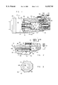
- FIG. 1 illustrates the screw compressor in which the unloader arrangement of the present invention is employed.
- FIG. 2 is an enlarged partial view of the piston unloader arrangement of FIG. 1.
- FIG. 3 is an end view of the piston unloader of the present invention taken along line 3--3 of FIG. 2.
- FIGS. 4a, 4b and 4c illustrate the unloading arrangement of the present invention with the piston unloader in full unload, intermediate and full load positions respectively.
- screw compressor 10 is comprised of rotor housing 12 and bearing housing 14. Disposed in rotor housing 12 is motor 16, male rotor 18 and female rotor 20. Extending from male rotor 18 is a shaft 22 on which motor rotor 24 is mounted. It will be appreciated, therefore, that male rotor 18 is the "driven" rotor in the preferred embodiment although the female rotor could likewise function as the driven rotor. Rotation of male rotor 18, in turn, causes the counter-rotation of female rotor 20 by virtue of their meshing engagement.
- Compressor 10 could also be of the open drive type, open drive compressors being compressors in which the motive power by which the compressor is driven is communicated from a remote source, such as a motor or engine, which does not form part of the flow path for refrigerant gas that passes through the compressor or the system in which the compressor is employed.
- a remote source such as a motor or engine
- Such gas is delivered to housing 12 from the evaporator of the refrigeration system in which compressor 10 is employed, such gas having been created by the evaporation process that occurs in the evaporator.
- Compressor 10 acts to pump or suck vaporized refrigerant gas from the evaporator through and around motor 16.
- Suction gas passing through and around motor 16 passes out of motor-rotor housing gap 28, rotor-stator gap 30 and into suction area 32 within the rotor housing.
- the gas next passes from suction area 32, through suction port 34 and into compressor working chamber 36 where it is enveloped in a chevron-shaped compression pocket defined by the wall of working chamber 36 and the lobes of the intermeshed male and female rotors.
- compression pockets are repetitively formed within the working chamber. Each such pocket traps suction gas at "suction pressure" within the working chamber and comes to be closed off from suction port 34 by virtue of the meshed counter-rotating relationship of the screw rotors and by the occlusion of the suction port by the rotation of the rotor lobes.
- the compression pockets are then circumferentially displaced toward high pressure end wall 38 of working chamber 36 by the continued counter-rotation of the rotors. As such displacement occurs, the volume of a compression pocket is reduced and the gas contained therein is compressed until such time as the pocket opens to discharge port 40. The now-compressed gas is expelled therethrough at "discharge pressure".
- the need for compressed gas in the system is, in turn, a function of the demand for cooling which the system experiences at any given time, that demand, in turn, being determinative of the rate of refrigerant vaporization that occurs in the evaporator of the system in which the compressor is employed.
- rotor housing 12 defines a bore 50 which is in flow communication with suction area 32 and/or suction port 34 or some other location in compressor 10 or the system in which compressor 10 is employed which is at suction pressure when the compressor is in operation.
- Rotor housing 12 also defines a series of generally axially running, physically non-overlapping unloader ports 52 along bore 50 that communicate between bore 50 and working chamber 36. Ports 52 need not necessarily be axially aligned along bore 40 and could be offset from one another around the bore. In the preferred embodiment, however, ports 52 are generally axially in-line along the bore.
- unloader piston 54 Disposed for movement in bore 50 is unloader piston 54 which includes a barrel portion 55 that is axially moveable in bore 50 and a control portion 56 that is axially positionable in a chamber 58. Chamber 58 is defined by bearing housing 14.
- Unloader ports 52 are generally elongated curvilinear slots which open both into bore 50 and working chamber 36. Ports 52 of the present invention do not physically overlap axially along the length of bore 50 and are separated in an axial sense with respect to their opening into the compressor's working chamber and into bore 50 as is illustrated at 100 in Drawing FIG. 4a.
- ports 52 do not physically overlap in the preferred embodiment of the present invention, circumstances are foreseeable where ports 52, due to the nature of the refrigerant used in compressor 10 or requirements associated with the casting process by which rotor housing 12 is formed might physically overlap.
- the unloader of the present invention will likewise function should ports 52 overlap although the present invention is primarily designed for those circumstances where the overlap of ports 52 does not occur.
- ports 52 constitute re-expansion volumes opening into the working chamber of the compressor which are detrimental to compressor efficiency. It has been found that the non-overlapping design for such ports, as set forth herein, reduces these so-called re-expansion volumes and thus least detrimentally affect the overall efficiency of the compressor by virtue of their existence.
- Unloader piston 54 is axially moveable and controllably positionable within bore 50 between the full unload position illustrated in FIG. 4a and the full load position illustrated in FIG. 4c.
- Backface 60 of control portion 56 of piston 54 is acted upon by a pressurized fluid so as to position barrel portion 55 of unloader piston 54 within bore 50 and with respect to the unloader ports.
- End face portion 62 of piston 54 is of a modified but uniform geometry, such geometry being, in the preferred embodiment, that of a truncated cone, so that no matter what the angular orientation of the end face 64 of piston 54 is with respect to the centerline 66 of bore 50, end face portion 62 of the unloader piston presents a uniform geometry to the unloader ports.
- the unloading arrangement of the present invention is entirely tolerant of any such rotation and is entirely alignment insensitive with respect to the orientation of the unloader piston to the unloader ports.
- Control of the position of unloader piston 54 is by the application of a relatively high pressure fluid, such as oil or refrigerant gas, to end face 60 of the unloader piston or by venting such fluid from chamber 58 to unload the compressor.
- a relatively high pressure fluid such as oil or refrigerant gas
- control portion 56 of unloader piston 54 within chamber 58 and, therefore, the precise positioning of barrel portion 55 of piston 54 in bore 50 is accomplished.
- Such precise control is achieved by the selective opening of load solenoid 68 to pressurize chamber 58 and by the opening of unload solenoid 70 in order to vent chamber 58.
- end face portion 62 of the unloader piston overlies a portion of unloader port 52a-1. In this position, end face portion 62 occludes unloader port 52a-1 very minimally. This very nominal/minimal loading of the compressor by piston 54, in its "full unload” position, makes the compressor immediately responsive to a demand for increased compressor capacity.
- unloader piston 54 is illustrated in an intermediate position in which both unloader ports 52a-1 and 52a-2 are overlapped by end face portion 62 of the unloader piston which maintains them in flow communication through bore 50 and makes them, in effect, overlapping unloader ports.
- unloader ports 52a-1 and 52a-2 are each partially occluded. Any further movement of piston 54 to load the compressor such that barrel portion 55 of piston 54 comes to completely occlude unloader port 52a-1 results in the transfer of capacity control from port 52a-1 to port 52a-2.
- the transfer of capacity control from one non-overlapping port to another thus occurs in a smooth and continuous fashion where there would otherwise be a deadband as the unloader piston moved without effect between the physically separated adjacent unloader ports.
- unloader piston 54 is shown in the full load position wherein communication of all of unloader ports 52a-1, 52a-2 and 52a-3 and, therefore, the working chamber of the compressor, with bore 50 is prevented.
- end face portion 62 of unloader piston 54 has moved past port 52a-3 to a location in unloader bore 50 in which it does not interact with any of the unloader ports and, therefore, has no effect.
- End portion 62 of piston 54 while immediately adjacent but not in communication with unloader port 52a-3, is positioned such that as soon piston 54 is caused to move in a direction which unloads the compressor, by the opening of unload solenoid 70 and the venting of chamber 58, communication is re-established between the compressor's working chamber 36 and bore 50 through unloader port 52a-3 and compressor unloading commences.
- the unloading arrangement of the present invention through the use of physically non-overlapping unloader ports which effectively overlap in operation and by the use of an unloader piston having an end face of uniform geometry, is such that continuous and smooth compressor loading and unloading is achieved while internal leakage within the compressor due to the unloading arrangement is minimized. Further, compressor efficiency is enhanced by, among other things, the minimization of the re-expansion volumes of the unloader ports.
Landscapes
- Engineering & Computer Science (AREA)
- Mechanical Engineering (AREA)
- General Engineering & Computer Science (AREA)
- Applications Or Details Of Rotary Compressors (AREA)
Abstract
Description
Claims (16)
Priority Applications (1)
| Application Number | Priority Date | Filing Date | Title |
|---|---|---|---|
| US09/070,827 US6135744A (en) | 1998-04-28 | 1998-04-28 | Piston unloader arrangement for screw compressors |
Applications Claiming Priority (1)
| Application Number | Priority Date | Filing Date | Title |
|---|---|---|---|
| US09/070,827 US6135744A (en) | 1998-04-28 | 1998-04-28 | Piston unloader arrangement for screw compressors |
Publications (1)
| Publication Number | Publication Date |
|---|---|
| US6135744A true US6135744A (en) | 2000-10-24 |
Family
ID=22097620
Family Applications (1)
| Application Number | Title | Priority Date | Filing Date |
|---|---|---|---|
| US09/070,827 Expired - Lifetime US6135744A (en) | 1998-04-28 | 1998-04-28 | Piston unloader arrangement for screw compressors |
Country Status (1)
| Country | Link |
|---|---|
| US (1) | US6135744A (en) |
Cited By (9)
| Publication number | Priority date | Publication date | Assignee | Title |
|---|---|---|---|---|
| US20100202904A1 (en) * | 2007-10-10 | 2010-08-12 | Carrier Corporation | Screw compressor pulsation damper |
| US20100209280A1 (en) * | 2007-10-01 | 2010-08-19 | Carrier Corporation | Screw compressor pulsation damper |
| US20100272580A1 (en) * | 2006-03-13 | 2010-10-28 | Wilson Francis P | Slide valve with hot gas bypass port |
| US20110038747A1 (en) * | 2008-06-24 | 2011-02-17 | Carrier Corporation | Automatic volume ratio variation for a rotary screw compressor |
| WO2011048618A1 (en) * | 2009-10-19 | 2011-04-28 | Refcomp Spa | Screw compressor with variable compression ratio |
| US20130156624A1 (en) * | 2011-12-16 | 2013-06-20 | Neville D. Kapadia | Slide valve for screw compressor |
| EP3165770A1 (en) * | 2009-03-26 | 2017-05-10 | Johnson Controls Technology Company | Compressor with a bypass port |
| US20170350398A1 (en) * | 2016-06-01 | 2017-12-07 | Trane International Inc. | Intermediate discharge port for a compressor |
| US20180356128A1 (en) * | 2017-06-12 | 2018-12-13 | Trane International Inc. | Converting compressor to variable vi compressor |
Citations (6)
| Publication number | Priority date | Publication date | Assignee | Title |
|---|---|---|---|---|
| US4042310A (en) * | 1974-06-21 | 1977-08-16 | Svenska Rotor Maskiner Aktiebolag | Screw compressor control means |
| US4544333A (en) * | 1980-09-19 | 1985-10-01 | Mitsubishi Jukogyo Kabushiki Kaisha | Capability control apparatus for a compressor |
| US4565508A (en) * | 1983-10-24 | 1986-01-21 | Stal Refrigeration Ab | Device for controlling the volumetric capacity of a screw compressor |
| US5203685A (en) * | 1992-06-23 | 1993-04-20 | American Standard Inc. | Piston unloader arrangement for screw compressors |
| US5211026A (en) * | 1991-08-19 | 1993-05-18 | American Standard Inc. | Combination lift piston/axial port unloader arrangement for a screw compresser |
| US5979168A (en) * | 1997-07-15 | 1999-11-09 | American Standard Inc. | Single-source gas actuation for screw compressor slide valve assembly |
-
1998
- 1998-04-28 US US09/070,827 patent/US6135744A/en not_active Expired - Lifetime
Patent Citations (6)
| Publication number | Priority date | Publication date | Assignee | Title |
|---|---|---|---|---|
| US4042310A (en) * | 1974-06-21 | 1977-08-16 | Svenska Rotor Maskiner Aktiebolag | Screw compressor control means |
| US4544333A (en) * | 1980-09-19 | 1985-10-01 | Mitsubishi Jukogyo Kabushiki Kaisha | Capability control apparatus for a compressor |
| US4565508A (en) * | 1983-10-24 | 1986-01-21 | Stal Refrigeration Ab | Device for controlling the volumetric capacity of a screw compressor |
| US5211026A (en) * | 1991-08-19 | 1993-05-18 | American Standard Inc. | Combination lift piston/axial port unloader arrangement for a screw compresser |
| US5203685A (en) * | 1992-06-23 | 1993-04-20 | American Standard Inc. | Piston unloader arrangement for screw compressors |
| US5979168A (en) * | 1997-07-15 | 1999-11-09 | American Standard Inc. | Single-source gas actuation for screw compressor slide valve assembly |
Cited By (16)
| Publication number | Priority date | Publication date | Assignee | Title |
|---|---|---|---|---|
| US20100272580A1 (en) * | 2006-03-13 | 2010-10-28 | Wilson Francis P | Slide valve with hot gas bypass port |
| US8221104B2 (en) * | 2006-03-13 | 2012-07-17 | Carrier Corporation | Screw compressor having a slide valve with hot gas bypass port |
| US20100209280A1 (en) * | 2007-10-01 | 2010-08-19 | Carrier Corporation | Screw compressor pulsation damper |
| US8459963B2 (en) | 2007-10-10 | 2013-06-11 | Carrier Corporation | Screw compressor pulsation damper |
| US20100202904A1 (en) * | 2007-10-10 | 2010-08-12 | Carrier Corporation | Screw compressor pulsation damper |
| US20110038747A1 (en) * | 2008-06-24 | 2011-02-17 | Carrier Corporation | Automatic volume ratio variation for a rotary screw compressor |
| US9850902B2 (en) | 2009-03-26 | 2017-12-26 | Johnson Controls Technology Company | Compressor with a bypass port |
| EP2411677B1 (en) * | 2009-03-26 | 2019-09-11 | Johnson Controls Technology Company | Compressor with a bypass port |
| EP3165770A1 (en) * | 2009-03-26 | 2017-05-10 | Johnson Controls Technology Company | Compressor with a bypass port |
| WO2011048618A1 (en) * | 2009-10-19 | 2011-04-28 | Refcomp Spa | Screw compressor with variable compression ratio |
| US8899950B2 (en) * | 2011-12-16 | 2014-12-02 | Gardner Denver, Inc. | Slide valve for screw compressor |
| US20130156624A1 (en) * | 2011-12-16 | 2013-06-20 | Neville D. Kapadia | Slide valve for screw compressor |
| US20170350398A1 (en) * | 2016-06-01 | 2017-12-07 | Trane International Inc. | Intermediate discharge port for a compressor |
| US11022122B2 (en) * | 2016-06-01 | 2021-06-01 | Trane International Inc. | Intermediate discharge port for a compressor |
| US20180356128A1 (en) * | 2017-06-12 | 2018-12-13 | Trane International Inc. | Converting compressor to variable vi compressor |
| US10883744B2 (en) * | 2017-06-12 | 2021-01-05 | Trane International Inc. | Converting compressor to variable VI compressor |
Similar Documents
| Publication | Publication Date | Title |
|---|---|---|
| EP1087142B1 (en) | Scroll compressor capacity control | |
| USRE41955E1 (en) | Capacity modulation for plural compressors | |
| US4383805A (en) | Gas compressor of the scroll type having delayed suction closing capacity modulation | |
| US5855475A (en) | Scroll compressor having bypass valves | |
| KR101253135B1 (en) | Compressor having piston assembly | |
| US4431388A (en) | Controlled suction unloading in a scroll compressor | |
| US7815423B2 (en) | Compressor with fluid injection system | |
| EP2050965A2 (en) | Compressor | |
| US6135744A (en) | Piston unloader arrangement for screw compressors | |
| JP2912812B2 (en) | Multi-stage rotary compressor | |
| US3527548A (en) | Screw compressor with capacity control | |
| KR930009734B1 (en) | Rotary compressor | |
| US5341658A (en) | Fail safe mechanical oil shutoff arrangement for screw compressor | |
| US5203685A (en) | Piston unloader arrangement for screw compressors | |
| US5201648A (en) | Screw compressor mechanical oil shutoff arrangement | |
| US11397034B2 (en) | Unloading system for variable speed compressor | |
| US12146490B2 (en) | Compression mechanism and scroll compressor | |
| JPS59185887A (en) | Vane type compressor | |
| US8206132B2 (en) | Slide valve actuation for overpressure safety | |
| KR960015823B1 (en) | Fluid comperessor | |
| JPH102288A (en) | Slide valve of screw-type hydraulic machine | |
| GB2269424A (en) | Preventing oil supply to screw compressor on shutdown | |
| JPS6332948Y2 (en) | ||
| JPH02252992A (en) | Multiple cylinder rotary compressor | |
| JPH02264185A (en) | fluid compressor |
Legal Events
| Date | Code | Title | Description |
|---|---|---|---|
| AS | Assignment |
Owner name: AMERICAN STANDARD INC., NEW JERSEY Free format text: ASSIGNMENT OF ASSIGNORS INTEREST;ASSIGNOR:ANDERSEN, GARRY E.;REEL/FRAME:009139/0588 Effective date: 19980428 |
|
| AS | Assignment |
Owner name: AMERICAN STANDARD INC., NEW JERSEY Free format text: ASSIGNMENT OF ASSIGNORS INTEREST;ASSIGNOR:MAYFIELD, ROBERT A.;REEL/FRAME:010775/0032 Effective date: 20000501 |
|
| STCF | Information on status: patent grant |
Free format text: PATENTED CASE |
|
| AS | Assignment |
Owner name: AMERICAN STANDARD INTERNATIONAL INC., NEW YORK Free format text: NOTICE OF ASSIGNMENT;ASSIGNOR:AMERICAN STANDARD INC., A CORPORATION OF DELAWARE;REEL/FRAME:011474/0650 Effective date: 20010104 |
|
| FEPP | Fee payment procedure |
Free format text: PAYOR NUMBER ASSIGNED (ORIGINAL EVENT CODE: ASPN); ENTITY STATUS OF PATENT OWNER: LARGE ENTITY |
|
| FPAY | Fee payment |
Year of fee payment: 4 |
|
| AS | Assignment |
Owner name: TRANE INTERNATIONAL INC., NEW YORK Free format text: CHANGE OF NAME;ASSIGNOR:AMERICAN STANDARD INTERNATIONAL INC.;REEL/FRAME:020733/0970 Effective date: 20071128 Owner name: TRANE INTERNATIONAL INC.,NEW YORK Free format text: CHANGE OF NAME;ASSIGNOR:AMERICAN STANDARD INTERNATIONAL INC.;REEL/FRAME:020733/0970 Effective date: 20071128 |
|
| FPAY | Fee payment |
Year of fee payment: 8 |
|
| FPAY | Fee payment |
Year of fee payment: 12 |