US6135682A - Multi-spindle phase controlled machining - Google Patents
Multi-spindle phase controlled machining Download PDFInfo
- Publication number
- US6135682A US6135682A US09/483,374 US48337400A US6135682A US 6135682 A US6135682 A US 6135682A US 48337400 A US48337400 A US 48337400A US 6135682 A US6135682 A US 6135682A
- Authority
- US
- United States
- Prior art keywords
- spindles
- cutters
- spindle
- cutting edges
- machine
- Prior art date
- Legal status (The legal status is an assumption and is not a legal conclusion. Google has not performed a legal analysis and makes no representation as to the accuracy of the status listed.)
- Expired - Lifetime
Links
Images


Classifications
-
- G—PHYSICS
- G05—CONTROLLING; REGULATING
- G05B—CONTROL OR REGULATING SYSTEMS IN GENERAL; FUNCTIONAL ELEMENTS OF SUCH SYSTEMS; MONITORING OR TESTING ARRANGEMENTS FOR SUCH SYSTEMS OR ELEMENTS
- G05B19/00—Program-control systems
- G05B19/02—Program-control systems electric
- G05B19/18—Numerical control [NC], i.e. automatically operating machines, in particular machine tools, e.g. in a manufacturing environment, so as to execute positioning, movement or co-ordinated operations by means of program data in numerical form
- G05B19/19—Numerical control [NC], i.e. automatically operating machines, in particular machine tools, e.g. in a manufacturing environment, so as to execute positioning, movement or co-ordinated operations by means of program data in numerical form characterised by positioning or contouring control systems, e.g. to control position from one programmed point to another or to control movement along a programmed continuous path
- G05B19/195—Controlling the position of several slides on one axis
-
- G—PHYSICS
- G05—CONTROLLING; REGULATING
- G05B—CONTROL OR REGULATING SYSTEMS IN GENERAL; FUNCTIONAL ELEMENTS OF SUCH SYSTEMS; MONITORING OR TESTING ARRANGEMENTS FOR SUCH SYSTEMS OR ELEMENTS
- G05B2219/00—Program-control systems
- G05B2219/30—Nc systems
- G05B2219/50—Machine tool, machine tool null till machine tool work handling
- G05B2219/50008—Multiple, multi tool head, parallel machining
-
- Y—GENERAL TAGGING OF NEW TECHNOLOGICAL DEVELOPMENTS; GENERAL TAGGING OF CROSS-SECTIONAL TECHNOLOGIES SPANNING OVER SEVERAL SECTIONS OF THE IPC; TECHNICAL SUBJECTS COVERED BY FORMER USPC CROSS-REFERENCE ART COLLECTIONS [XRACs] AND DIGESTS
- Y10—TECHNICAL SUBJECTS COVERED BY FORMER USPC
- Y10T—TECHNICAL SUBJECTS COVERED BY FORMER US CLASSIFICATION
- Y10T409/00—Gear cutting, milling, or planing
- Y10T409/30—Milling
- Y10T409/303752—Process
-
- Y—GENERAL TAGGING OF NEW TECHNOLOGICAL DEVELOPMENTS; GENERAL TAGGING OF CROSS-SECTIONAL TECHNOLOGIES SPANNING OVER SEVERAL SECTIONS OF THE IPC; TECHNICAL SUBJECTS COVERED BY FORMER USPC CROSS-REFERENCE ART COLLECTIONS [XRACs] AND DIGESTS
- Y10—TECHNICAL SUBJECTS COVERED BY FORMER USPC
- Y10T—TECHNICAL SUBJECTS COVERED BY FORMER US CLASSIFICATION
- Y10T409/00—Gear cutting, milling, or planing
- Y10T409/30—Milling
- Y10T409/304312—Milling with means to dampen vibration
Definitions
- Very large multi-spindle machine tools e.g. profilers used in the aircraft industry, have large translatable gantries supporting multiple spindle carriers.
- Each of the carriers contains an electric motor to power the spindle and a cutting tool mounted to an end of the spindle.
- One such a machine is known as a rail-type five-axis gantry CNC vertical profiling machine, commercially manufactured by Cincinnati Machine, assignee of this invention, (formerly by Cincinnati Milacron, Inc). This type of machine is used to sculpt very long workpieces with the cutting tools held in three or more spindle carriers moving under command of a computer control.
- multi-spindle machines do not have spindle speed control interaction between spindles. Slight variation in speed from one spindle to the next results in a processing of the cutting teeth relative to each other. This results in a variation in phasing of the teeth and thus an adding of forces and torques and subtracting of forces and torques with respect to time. The forces and torques are reacted from the cutters, back through the spindles, the spindle carriers, and the gantry. The variation can result in poor finish and when forces combine at maximum they may induce chatter or excessive deflection. The cyclic nature of the variation causes vibrations that results in increased wear and a more rapid onset of a misalignment condition of the machine. The maximum amount of additive forces and torques occurs when all of the cutting edges engage workpieces simultaneously.
- a multiple-spindle machine includes a support and a number of spindles rotatably mounted to the support. Each of the spindles is operably connected and in driving relationship to a respective one of a like number of cutters and each of the cutters has two or more cutting edges. Each of the spindles is operably connected to a respective one of a like number of individually controllable electric motors for rotatably driving each of the spindles respectively.
- the phase control means is programmed to adjust speed of the spindles such that cutting edge angular positions are out of phase by an amount equal to 360 degrees divided by product of the number of the spindles and the number of cutting edges of each of the cutters.
- a more particular embodiment of the invention includes a number of spindle carriers wherein each of the spindles and the motors are carried on one of each of the spindle carriers.
- a vertically translatable slide supports the spindle carriers and the vertically translatable slide is mounted on a horizontally translatable gantry.
- the spindles are horizontal 4-axis spindles while in another embodiment the spindles are vertical 5-axis spindles.
- a more particular embodiment of the invention includes using angular position detecting means for detecting angular positions of each of the spindles and using angular speed detecting means for detecting angular speed of each of the spindles.
- the angular position detecting means and the angular speed detecting means are used to transmit signals to the phase control means and the phase control means uses the signals to adjust the speed of each of the spindles such that cutting edge angular positions of the cutters are out of phase with those of the other cutters.
- the phase control adjusts speed of the spindles such that cutting edge angular positions are out of phase by an amount equal to 360 degrees divided by product of the number of the spindles and the number of cutting edges of each of the cutters.
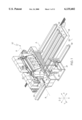
- FIG. 1 is a perspective view illustration of a machine tool having a long bed, a gantry movable along a length of the bed, and spindle carriers on a support mounted on the gantry.
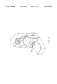
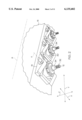
- FIG. 2 is an enlarged perspective view illustration of spindle carriers supported a slide 15 of the machine tool in FIG. 1.
- FIG. 3 is a cross-sectional view illustration of a spindle cartridge containing a spindle and an electric motor mounted on one of the carriers in FIGS. 1 and 2.
- FIG. 4 is a schematic illustration of the speed control and phasing control of the present invention for spindles of the machine tool in FIG. 1.
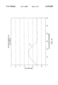
- FIG. 7 is a graphical illustration of an approximate total reaction forces TFX in the X-direction with a worst case X direction phasing of the 3 spindles in FIGS. 1 and 2 cutting simultaneously as may occur in the prior art.
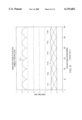
- FIG. 9 is a graphical illustration of an approximate total X-direction reaction forces TFX in the X-direction for best case phasing with a 20 degree phase delay between each of teeth of the 3 different spindles.
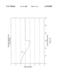
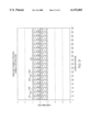
- FIG. 10 is a graphical illustration of an approximate total Y-direction reaction forces TFY for in the Y-direction for best case phasing with a 20 degree phase delay between each of teeth of the 3 different spindles.
- FIG. 11 is a perspective view of a horizontal 4-axis spindle.
- FIGS. 1 and 2 Illustrated in FIGS. 1 and 2 is a very large CNC machine 10 typically used in the aircraft industry.
- This machine 10 is known as a rail-type five-axis gantry CNC vertical profiling machine, commercially manufactured by Cincinnati Machine (formerly by Cincinnati Milacron, Inc.), assignee of this invention.
- the machine 10 is used to sculpt very long workpieces 11 with cutters 12 held in three spindles 30 (shown more particularly in FIG. 2) mounted on spindle carriers 13 moving under command of a computer control 14.
- the spindle carriers 13 are supported for vertical movement on a support which in the exemplary embodiment is a slide 15.
- the slide 15 moves transversely of the bed on the ways 16 of a movable bridge or gantry 17 to which it is rotatably mounted.
- the spindle 30 includes a tool holder 34 adapted for receiving and retaining various cutting tools such as the cutters 12. Relative positioning between work piece and each of the spindle 30 is done along 3 linear motion axes X, Y, and Z and about two rotational axes, slide trunnion axis B about which the slide 15 pivots in a X and Z axes plane, and spindle trunnion axis A about which each of the spindles 30 pivot and which is perpendicular to trunnion axis B.
- the gantry 17 moves horizontally along the length of the bed 18 which extends along the X axis and the slide 15 moves vertically in a direction parallel to the Z axis.
- the spindle carriers 13 translate in a direction parallel to the Y axis as well as being capable to pivot about the trunnion axis B.
- Each of the spindles 30 operably connected and in driving relationship to a respective one of a like number of the cutters 12 and each of the cutters having two or more cutting edges or teeth 32.
- the exemplary embodiment illustrated herein has 3 each of the spindles 30 and spindle carriers 13 and has 6 of the cutter teeth 32 on each of the cutters 12 as illustrated more particularly in FIG. 4.
- each of the spindles 30 is operably connected to a respective one of a like number (3) of individually controllable electric motors 36 for rotatably driving each of the spindles respectively.
- FIG. 3 illustrates the spindle 30 and the electric motor 36 mounted in a spindle cartridge 37 which in turn is mounted on spindle carrier 13 in FIGS. 1 and 2.
- a control means such as the control 14 controls the angular speed W of each electric motor 36 and the angular position 40 (i.e. in degrees) of its associated spindle 30.
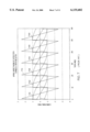
- FIG. 8 illustrates a simplified calculation of total Y-direction worst case phasing of the 3 spindles cutting simultaneously.
- the total Y-direction reaction forces TFY is a summation of first through sixth single Y-direction reaction force FY1-FY6 of the six cutter teeth on the cutter 12. Note that the total Y-direction force TFY never exhibits a negative (opposite direction) component and thus there is never a canceling effect for the summation.
- the highlighted summation shows a peak of 6 times the peak force of that expected from an individual cutting edge force profile. Note that there are 3 teeth in the cuter for each of the 3 spindles.
- FIG. 10 similarly for the best case Y-direction phasing shows little change in the total force however, the 18 cycles have less peak to peak variation than the worse case 6 cycle variation illustrated in FIG. 8. This illustrates how the invention produces a much smoother cut, from a vibration perspective.
- a more particular embodiment of the invention includes angular position detecting means 50 for detecting angular positions 40 of each of the spindles and angular speed detecting means 52 for detecting angular speed W of each of the spindles.
- the angular position detecting means 50 and the angular speed detecting means 52 may be angular position and speed feedback transducers that are in signal transmitting relationship with the phase control means 44.
- the phase control means is programmed to adjust speed of the spindles such that cutting edge angular positions are out of phase by an amount equal to 360 degrees divided by product of the number of the spindles 30 and the number of cutting edges or teeth 32 of each of the cutters 12.
- Optimum angle (in degrees) between teeth (360/)/[(number of spindles) ⁇ (number of cutter teeth per spindle)].
- FIGS. 1 and 2 illustrate the invention for a vertical 5-axis machine 10.
- the invention may be applied to many types of machine tools including but not limited to a machine having horizontal 4-axis spindles 60 as illustrated in FIG. 11.
Landscapes
- Engineering & Computer Science (AREA)
- Human Computer Interaction (AREA)
- Manufacturing & Machinery (AREA)
- Physics & Mathematics (AREA)
- General Physics & Mathematics (AREA)
- Automation & Control Theory (AREA)
- Automatic Control Of Machine Tools (AREA)
Abstract
Description
Claims (11)
Priority Applications (1)
| Application Number | Priority Date | Filing Date | Title |
|---|---|---|---|
| US09/483,374 US6135682A (en) | 2000-01-14 | 2000-01-14 | Multi-spindle phase controlled machining |
Applications Claiming Priority (1)
| Application Number | Priority Date | Filing Date | Title |
|---|---|---|---|
| US09/483,374 US6135682A (en) | 2000-01-14 | 2000-01-14 | Multi-spindle phase controlled machining |
Publications (1)
| Publication Number | Publication Date |
|---|---|
| US6135682A true US6135682A (en) | 2000-10-24 |
Family
ID=23919796
Family Applications (1)
| Application Number | Title | Priority Date | Filing Date |
|---|---|---|---|
| US09/483,374 Expired - Lifetime US6135682A (en) | 2000-01-14 | 2000-01-14 | Multi-spindle phase controlled machining |
Country Status (1)
| Country | Link |
|---|---|
| US (1) | US6135682A (en) |
Cited By (8)
| Publication number | Priority date | Publication date | Assignee | Title |
|---|---|---|---|---|
| US20030190203A1 (en) * | 2002-04-08 | 2003-10-09 | Marusich Troy D. | High frequency tooth pass cutting method |
| WO2004018149A1 (en) * | 2002-08-23 | 2004-03-04 | Eung Gyu Jung | Cnc milling machine provided with remote control panel |
| US6708866B2 (en) | 2001-09-26 | 2004-03-23 | Nova-Tech Engineering, Inc. | Method and apparatus for machine tooling, such as friction stir welder |
| US20080056838A1 (en) * | 2002-04-08 | 2008-03-06 | Marusich Troy D | High frequency tooth pass cutting method |
| US20080175680A1 (en) * | 2002-04-08 | 2008-07-24 | Marusich Troy D | High-frequency tooth pass cutting device and method |
| US20100063609A1 (en) * | 2008-09-05 | 2010-03-11 | Cincinnati Machine, Llc | Multi-Spindle Phase Controlled Machining |
| US20130309034A1 (en) * | 2012-05-17 | 2013-11-21 | Okuma Corporation | Machining vibration suppressing method and machining vibration suppressing apparatus for machine tool |
| WO2014187891A3 (en) * | 2013-05-24 | 2015-01-15 | Basf Se | Method for operating machines comprising moving parts and arranged on a common support |
Citations (22)
| Publication number | Priority date | Publication date | Assignee | Title |
|---|---|---|---|---|
| US1723999A (en) * | 1927-06-23 | 1929-08-13 | James L Bernard | Facing machine |
| US2483535A (en) * | 1944-07-31 | 1949-10-04 | Giddings & Lewis | Reciprocatory drive for machine tools |
| US3744353A (en) * | 1970-08-25 | 1973-07-10 | H Rohs | Method and means for preventing regenerative chatter in a machine tool, particularly in a lathe |
| US3823644A (en) * | 1973-01-30 | 1974-07-16 | Colt Ind Operating Corp | Swivel head assembly for five axis machine tool |
| US3946298A (en) * | 1974-06-06 | 1976-03-23 | Acme-Cleveland Corporation | Shaft positioning mechanism |
| US3945694A (en) * | 1974-11-04 | 1976-03-23 | Cincinnati Milacron-Heald Corporation | Toolhead |
| US4047469A (en) * | 1974-11-05 | 1977-09-13 | Agency Of Industrial Science & Technology | Method for suppressing chatter vibrations in a machine tool |
| US4261675A (en) * | 1978-12-06 | 1981-04-14 | Kearney & Trecker Corporation | Machine tool with pulsating cutting force |
| US4535527A (en) * | 1982-11-16 | 1985-08-20 | Alfing Kessler Sondermaschinen Gmbh | Tool exchanging device for a multi-spindle machine tool |
| US4611934A (en) * | 1985-09-09 | 1986-09-16 | Cincinnati Milacron Inc. | Device for preloading bearings |
| US4640158A (en) * | 1983-08-06 | 1987-02-03 | Index Werke Komm.-Ges. Hahn & Tessky | Multiple-spindle automatic lathe |
| US5037252A (en) * | 1989-01-30 | 1991-08-06 | Matsushita Electric Industrial Co., Ltd. | Multi-spindle synchronous drive unit and gear cutting machine employing the same |
| US5115546A (en) * | 1987-04-17 | 1992-05-26 | Yamazaki Mazak Corporation | Complex machining machine tool |
| US5117544A (en) * | 1988-04-19 | 1992-06-02 | Nakamura-Tome Precision Ind. Co., Ltd. | Two-spindle opposed type cnc lathe |
| US5193953A (en) * | 1990-08-13 | 1993-03-16 | Fortuna-Werke Maschinenfabrik Gmbh | High-speed drilling or milling spindle |
| US5221185A (en) * | 1991-08-05 | 1993-06-22 | General Electric Company | Method and apparatus for synchronizing rotating machinery to reduce noise |
| US5390545A (en) * | 1993-01-11 | 1995-02-21 | Caterpillar Inc. | Apparatus for measuring torsional vibrations of rotating machinery |
| US5417132A (en) * | 1993-01-19 | 1995-05-23 | Alan R. Pfaff | Rotary cutting dies |
| US5713253A (en) * | 1994-10-07 | 1998-02-03 | Toshiba Kikai Kabushiki Kaisha | Rotational machining method |
| US5784273A (en) * | 1996-11-07 | 1998-07-21 | Madhavan; Poovanpilli G. | Method and system for predicting limit cycle oscillations and control method and system utilizing same |
| US5876155A (en) * | 1997-05-15 | 1999-03-02 | Ford Global Technologies, Inc. | Method of eliminating chatter in plunge cutting with cutters at different diameters and depths |
| US5920974A (en) * | 1997-05-15 | 1999-07-13 | Northrop Grumman Corporation | Reconfigurable gantry tool and system |
-
2000
- 2000-01-14 US US09/483,374 patent/US6135682A/en not_active Expired - Lifetime
Patent Citations (22)
| Publication number | Priority date | Publication date | Assignee | Title |
|---|---|---|---|---|
| US1723999A (en) * | 1927-06-23 | 1929-08-13 | James L Bernard | Facing machine |
| US2483535A (en) * | 1944-07-31 | 1949-10-04 | Giddings & Lewis | Reciprocatory drive for machine tools |
| US3744353A (en) * | 1970-08-25 | 1973-07-10 | H Rohs | Method and means for preventing regenerative chatter in a machine tool, particularly in a lathe |
| US3823644A (en) * | 1973-01-30 | 1974-07-16 | Colt Ind Operating Corp | Swivel head assembly for five axis machine tool |
| US3946298A (en) * | 1974-06-06 | 1976-03-23 | Acme-Cleveland Corporation | Shaft positioning mechanism |
| US3945694A (en) * | 1974-11-04 | 1976-03-23 | Cincinnati Milacron-Heald Corporation | Toolhead |
| US4047469A (en) * | 1974-11-05 | 1977-09-13 | Agency Of Industrial Science & Technology | Method for suppressing chatter vibrations in a machine tool |
| US4261675A (en) * | 1978-12-06 | 1981-04-14 | Kearney & Trecker Corporation | Machine tool with pulsating cutting force |
| US4535527A (en) * | 1982-11-16 | 1985-08-20 | Alfing Kessler Sondermaschinen Gmbh | Tool exchanging device for a multi-spindle machine tool |
| US4640158A (en) * | 1983-08-06 | 1987-02-03 | Index Werke Komm.-Ges. Hahn & Tessky | Multiple-spindle automatic lathe |
| US4611934A (en) * | 1985-09-09 | 1986-09-16 | Cincinnati Milacron Inc. | Device for preloading bearings |
| US5115546A (en) * | 1987-04-17 | 1992-05-26 | Yamazaki Mazak Corporation | Complex machining machine tool |
| US5117544A (en) * | 1988-04-19 | 1992-06-02 | Nakamura-Tome Precision Ind. Co., Ltd. | Two-spindle opposed type cnc lathe |
| US5037252A (en) * | 1989-01-30 | 1991-08-06 | Matsushita Electric Industrial Co., Ltd. | Multi-spindle synchronous drive unit and gear cutting machine employing the same |
| US5193953A (en) * | 1990-08-13 | 1993-03-16 | Fortuna-Werke Maschinenfabrik Gmbh | High-speed drilling or milling spindle |
| US5221185A (en) * | 1991-08-05 | 1993-06-22 | General Electric Company | Method and apparatus for synchronizing rotating machinery to reduce noise |
| US5390545A (en) * | 1993-01-11 | 1995-02-21 | Caterpillar Inc. | Apparatus for measuring torsional vibrations of rotating machinery |
| US5417132A (en) * | 1993-01-19 | 1995-05-23 | Alan R. Pfaff | Rotary cutting dies |
| US5713253A (en) * | 1994-10-07 | 1998-02-03 | Toshiba Kikai Kabushiki Kaisha | Rotational machining method |
| US5784273A (en) * | 1996-11-07 | 1998-07-21 | Madhavan; Poovanpilli G. | Method and system for predicting limit cycle oscillations and control method and system utilizing same |
| US5876155A (en) * | 1997-05-15 | 1999-03-02 | Ford Global Technologies, Inc. | Method of eliminating chatter in plunge cutting with cutters at different diameters and depths |
| US5920974A (en) * | 1997-05-15 | 1999-07-13 | Northrop Grumman Corporation | Reconfigurable gantry tool and system |
Non-Patent Citations (4)
| Title |
|---|
| Cincinnati Milacron, "Rail-Type 3- and 5-Axis Gantry CNC Vertical Profiling Machines", Publication No. SP-161, 14 pages, 1989 Cincinnati Milacron Marketing Company. |
| Cincinnati Milacron, Rail Type 3 and 5 Axis Gantry CNC Vertical Profiling Machines , Publication No. SP 161, 14 pages, 1989 Cincinnati Milacron Marketing Company. * |
| Products, "Productive Bed-Type and Rail-Type Machines Matched to Your Production Needs", Wide Range Profiler, http://www.cinmach.com/products/profiler-- wide.htm, 1 page, Oct. 27, 1999. |
| Products, Productive Bed Type and Rail Type Machines Matched to Your Production Needs , Wide Range Profiler, http://www.cinmach.com/products/profiler wide.htm, 1 page, Oct. 27, 1999. * |
Cited By (16)
| Publication number | Priority date | Publication date | Assignee | Title |
|---|---|---|---|---|
| US6708866B2 (en) | 2001-09-26 | 2004-03-23 | Nova-Tech Engineering, Inc. | Method and apparatus for machine tooling, such as friction stir welder |
| US20030190203A1 (en) * | 2002-04-08 | 2003-10-09 | Marusich Troy D. | High frequency tooth pass cutting method |
| US20060198709A1 (en) * | 2002-04-08 | 2006-09-07 | Third Wave Systems | High frequency tooth pass cutting method |
| US20080056838A1 (en) * | 2002-04-08 | 2008-03-06 | Marusich Troy D | High frequency tooth pass cutting method |
| US20080175680A1 (en) * | 2002-04-08 | 2008-07-24 | Marusich Troy D | High-frequency tooth pass cutting device and method |
| WO2004018149A1 (en) * | 2002-08-23 | 2004-03-04 | Eung Gyu Jung | Cnc milling machine provided with remote control panel |
| US20100063609A1 (en) * | 2008-09-05 | 2010-03-11 | Cincinnati Machine, Llc | Multi-Spindle Phase Controlled Machining |
| US8090468B2 (en) * | 2008-09-05 | 2012-01-03 | Mag Ias, Llc | Multi-spindle phase controlled machining |
| US20130309034A1 (en) * | 2012-05-17 | 2013-11-21 | Okuma Corporation | Machining vibration suppressing method and machining vibration suppressing apparatus for machine tool |
| CN103419076A (en) * | 2012-05-17 | 2013-12-04 | 大隈株式会社 | Machining vibration suppressing method and machining vibration suppressing apparatus for machine tool |
| US9221143B2 (en) * | 2012-05-17 | 2015-12-29 | Okuma Corporation | Machining vibration suppressing method and machining vibration suppressing apparatus for machine tool |
| CN103419076B (en) * | 2012-05-17 | 2017-03-01 | 大隈株式会社 | The processing vibration suppressing method of lathe and processing equipment for inhibiting of vibration |
| WO2014187891A3 (en) * | 2013-05-24 | 2015-01-15 | Basf Se | Method for operating machines comprising moving parts and arranged on a common support |
| CN105408658A (en) * | 2013-05-24 | 2016-03-16 | 巴斯夫欧洲公司 | Method for operating machines comprising moving parts and arranged on a common support |
| US20160121369A1 (en) * | 2013-05-24 | 2016-05-05 | Basf Se | Method for Operating Machines Having Moving Parts and Arranged Jointly on a Support |
| US9737911B2 (en) * | 2013-05-24 | 2017-08-22 | Basf Se | Method for operating machines having moving parts and arranged jointly on a support |
Similar Documents
| Publication | Publication Date | Title |
|---|---|---|
| US4457193A (en) | Machine-tool comprising two opposed coaxial spindles | |
| EP1240974B1 (en) | A machine tool with at least two machining units | |
| US11872653B2 (en) | Device for aligning and positioning a workpiece relative to a laser beam of a laser processing machine | |
| EP0819499A3 (en) | Method for multiple-spindle machining | |
| JP4843238B2 (en) | Method for chamfering and / or deburring edges of bevel gear teeth | |
| JP2008540145A (en) | Machine tool with two clamping points on separate carriages | |
| KR960037186A (en) | Machine tools with multiple spindles | |
| JPH06504491A (en) | Multi-axis machine tool for machining workpieces gripped by independently controlled clamping and feeding means on each side of the tool assembly | |
| JP4681191B2 (en) | 2-spindle facing lathe | |
| JP2012525983A (en) | Synchronous machining system and synchronous machining method | |
| US6135682A (en) | Multi-spindle phase controlled machining | |
| EP2687307B1 (en) | Method for machining curved surface using lathe | |
| WO2007118241A2 (en) | Compact high precision multiple spindle computer controlled machine tool | |
| CN210208661U (en) | Hard rail compound lathe | |
| TW201914739A (en) | Machine tool | |
| JPS59129601A (en) | Machine tool | |
| JPH04283037A (en) | Machine tool | |
| US6964217B2 (en) | Multispindle lathe | |
| JPH0763962B2 (en) | Machine tools for machining flat workpieces | |
| RU98350U1 (en) | MULTI-PURPOSE MACHINE WITH NUMERIC SOFTWARE CONTROL AND AUTOMATIC TOOL CHANGE | |
| EP2121228B1 (en) | Machine tool and method for cutting elongated profiled elements | |
| CN211072099U (en) | Multi-gear part shaft tooth double-sided chamfering machine | |
| US6484611B1 (en) | Lathe | |
| EP3696634B1 (en) | Machine tool | |
| CN102626936A (en) | Numerical control woodworking machine tool and method for finely processing wood product thereby |
Legal Events
| Date | Code | Title | Description |
|---|---|---|---|
| AS | Assignment |
Owner name: UNOVA IP CORP., CALIFORNIA Free format text: ASSIGNMENT OF ASSIGNORS INTEREST;ASSIGNOR:MCCALMONT, PAUL E.;REEL/FRAME:010637/0849 Effective date: 20000113 |
|
| STCF | Information on status: patent grant |
Free format text: PATENTED CASE |
|
| FEPP | Fee payment procedure |
Free format text: PAYOR NUMBER ASSIGNED (ORIGINAL EVENT CODE: ASPN); ENTITY STATUS OF PATENT OWNER: LARGE ENTITY |
|
| FPAY | Fee payment |
Year of fee payment: 4 |
|
| AS | Assignment |
Owner name: SILVER POINT FINANCE, LLC, CONNECTICUT Free format text: SECURITY AGREEMENT;ASSIGNORS:MAG INDUSTRIAL AUTOMATION SYSTEMS, LLC;CINCINNATI MACHINE, LLC;LAMB TECHNICON, LLC;AND OTHERS;REEL/FRAME:016513/0080 Effective date: 20050403 |
|
| AS | Assignment |
Owner name: MAGUS GMBH, SWITZERLAND Free format text: ASSIGNMENT OF ASSIGNORS INTEREST;ASSIGNOR:UNOVA IP CORP.;REEL/FRAME:015980/0302 Effective date: 20050422 |
|
| AS | Assignment |
Owner name: MAGUS INTELLECTUAL PROPERTY GMBH, SWITZERLAND Free format text: CORRECTIVE ASSIGNMENT TO CORRECT THE NAME OF THE ASSIGNEE TO MAGUS INTELLECTUAL PROPERTY GMBH PREVIOUSLY RECORDED ON REEL 015980 FRAME 0302;ASSIGNOR:UNOVA IP CORP.;REEL/FRAME:017223/0824 Effective date: 20050422 |
|
| AS | Assignment |
Owner name: CINCINNATI MACHINE, LLC, NEW YORK Free format text: ASSIGNMENT OF ASSIGNORS INTEREST;ASSIGNOR:MAGUS INTELLECTUAL PROPERTY GMBH;REEL/FRAME:020288/0581 Effective date: 20071218 |
|
| AS | Assignment |
Owner name: GENERAL ELECTRIC CAPITAL CORPORATION, AS AGENT, NE Free format text: SECURITY AGREEMENT;ASSIGNORS:MAG INDUSTRIAL AUTOMATION SYSTEMS, LLC;CINCINNATI MACHINE, LLC;FADAL MACHINING CENTERS, LLC;AND OTHERS;REEL/FRAME:020309/0753 Effective date: 20071228 |
|
| AS | Assignment |
Owner name: LAMB ASSEMBLY AND TEST, LLC, MICHIGAN Free format text: RELEASE BY SECURED PARTY;ASSIGNOR:SILVER POINT FINANCE, LLC;REEL/FRAME:020353/0284 Effective date: 20071220 Owner name: CINCINNATI MACHINE, LLC, MICHIGAN Free format text: RELEASE BY SECURED PARTY;ASSIGNOR:SILVER POINT FINANCE, LLC;REEL/FRAME:020353/0284 Effective date: 20071220 Owner name: MAG INDUSTRIAL AUTOMATION SYSTEMS, LLC, MICHIGAN Free format text: RELEASE BY SECURED PARTY;ASSIGNOR:SILVER POINT FINANCE, LLC;REEL/FRAME:020353/0284 Effective date: 20071220 Owner name: LAMB TECHNICON, LLC, MICHIGAN Free format text: RELEASE BY SECURED PARTY;ASSIGNOR:SILVER POINT FINANCE, LLC;REEL/FRAME:020353/0284 Effective date: 20071220 |
|
| FPAY | Fee payment |
Year of fee payment: 8 |
|
| AS | Assignment |
Owner name: CINCINNATI MACHINE, LLC, KENTUCKY Free format text: RELEASE OF SECURITY INTEREST;ASSIGNOR:GENERAL ELECTRIC CAPITAL CORPORATION;REEL/FRAME:024812/0186 Effective date: 20100803 |
|
| AS | Assignment |
Owner name: BURDALE CAPITAL FINANCE, INC., CONNECTICUT Free format text: SECURITY AGREEMENT;ASSIGNOR:CINCINNATI MACHINE, LLC;REEL/FRAME:024820/0530 Effective date: 20100803 |
|
| AS | Assignment |
Owner name: MAG IAS, LLC, A DELAWARE LIMITED LIABILITY COMPANY Free format text: ASSIGNMENT OF ASSIGNORS INTEREST;ASSIGNOR:CINCINNATI MACHINE, LLC;REEL/FRAME:025586/0666 Effective date: 20101221 |
|
| FPAY | Fee payment |
Year of fee payment: 12 |
|
| AS | Assignment |
Owner name: WELLS FARGO BANK, NATIONAL ASSOCIATION, ILLINOIS Free format text: ASSIGNMENT OF ASSIGNORS INTEREST;ASSIGNOR:BURDALE CAPITAL FINANCE, INC.;REEL/FRAME:028794/0724 Effective date: 20120711 |
|
| AS | Assignment |
Owner name: WELLS FARGO BANK, NATIONAL ASSOCIATION, ILLINOIS Free format text: SECURITY AGREEMENT;ASSIGNOR:MAG IAS, LLC;REEL/FRAME:031501/0920 Effective date: 20130729 |
|
| AS | Assignment |
Owner name: FIVES MACHINING SYSTEMS, INC., WISCONSIN Free format text: CHANGE OF NAME;ASSIGNOR:MAG IAS, LLC;REEL/FRAME:031481/0448 Effective date: 20130729 |
|
| AS | Assignment |
Owner name: CINCINNATI MACHINE, LLC, KENTUCKY Free format text: RELEASE OF SECURITY INTEREST;ASSIGNOR:WELLS FARGO BANK, NATIONAL ASSOCIATIION;REEL/FRAME:032190/0942 Effective date: 20130729 |