US6135618A - Electrical fixture and method of installing an electrical fixture - Google Patents
Electrical fixture and method of installing an electrical fixture Download PDFInfo
- Publication number
- US6135618A US6135618A US09/193,930 US19393098A US6135618A US 6135618 A US6135618 A US 6135618A US 19393098 A US19393098 A US 19393098A US 6135618 A US6135618 A US 6135618A
- Authority
- US
- United States
- Prior art keywords
- base
- cover
- receptacle
- providing
- carried
- Prior art date
- Legal status (The legal status is an assumption and is not a legal conclusion. Google has not performed a legal analysis and makes no representation as to the accuracy of the status listed.)
- Expired - Lifetime
Links
- 238000000034 method Methods 0.000 title claims description 15
- 238000004891 communication Methods 0.000 claims description 11
- 210000001364 upper extremity Anatomy 0.000 claims 4
- 210000003141 lower extremity Anatomy 0.000 claims 2
- 230000007935 neutral effect Effects 0.000 description 15
- 238000012986 modification Methods 0.000 description 3
- 230000004048 modification Effects 0.000 description 3
- 239000000853 adhesive Substances 0.000 description 1
- 230000001070 adhesive effect Effects 0.000 description 1
- 230000008878 coupling Effects 0.000 description 1
- 238000010168 coupling process Methods 0.000 description 1
- 238000005859 coupling reaction Methods 0.000 description 1
- 238000005286 illumination Methods 0.000 description 1
- 238000009434 installation Methods 0.000 description 1
- 239000000463 material Substances 0.000 description 1
- 239000002184 metal Substances 0.000 description 1
Images


Classifications
-
- F—MECHANICAL ENGINEERING; LIGHTING; HEATING; WEAPONS; BLASTING
- F21—LIGHTING
- F21V—FUNCTIONAL FEATURES OR DETAILS OF LIGHTING DEVICES OR SYSTEMS THEREOF; STRUCTURAL COMBINATIONS OF LIGHTING DEVICES WITH OTHER ARTICLES, NOT OTHERWISE PROVIDED FOR
- F21V21/00—Supporting, suspending, or attaching arrangements for lighting devices; Hand grips
- F21V21/02—Wall, ceiling, or floor bases; Fixing pendants or arms to the bases
-
- F—MECHANICAL ENGINEERING; LIGHTING; HEATING; WEAPONS; BLASTING
- F21—LIGHTING
- F21S—NON-PORTABLE LIGHTING DEVICES; SYSTEMS THEREOF; VEHICLE LIGHTING DEVICES SPECIALLY ADAPTED FOR VEHICLE EXTERIORS
- F21S8/00—Lighting devices intended for fixed installation
- F21S8/03—Lighting devices intended for fixed installation of surface-mounted type
- F21S8/033—Lighting devices intended for fixed installation of surface-mounted type the surface being a wall or like vertical structure, e.g. building facade
-
- H—ELECTRICITY
- H02—GENERATION; CONVERSION OR DISTRIBUTION OF ELECTRIC POWER
- H02G—INSTALLATION OF ELECTRIC CABLES OR LINES, OR OF COMBINED OPTICAL AND ELECTRIC CABLES OR LINES
- H02G3/00—Installations of electric cables or lines or protective tubing therefor in or on buildings, equivalent structures or vehicles
- H02G3/02—Details
- H02G3/08—Distribution boxes; Connection or junction boxes
- H02G3/10—Distribution boxes; Connection or junction boxes for surface mounting on a wall
-
- H—ELECTRICITY
- H02—GENERATION; CONVERSION OR DISTRIBUTION OF ELECTRIC POWER
- H02G—INSTALLATION OF ELECTRIC CABLES OR LINES, OR OF COMBINED OPTICAL AND ELECTRIC CABLES OR LINES
- H02G3/00—Installations of electric cables or lines or protective tubing therefor in or on buildings, equivalent structures or vehicles
- H02G3/02—Details
- H02G3/08—Distribution boxes; Connection or junction boxes
- H02G3/18—Distribution boxes; Connection or junction boxes providing line outlets
- H02G3/20—Ceiling roses or other lighting sets
Definitions
- This invention relates generally to electrical fixtures and, more particularly, to an improved electrical fixture housing and method of installing an electrical fixture.
- a typical electrical fixture such as an electrical light fixture, normally includes a plate and a removable cover.
- the plate is normally fastened to a wall at an outlet box having hot and neutral leads.
- typical installation normally includes coupling hot and neutral connector leads carried by the cover with the hot and neutral leads of the outlet box for facilitating the transfer of electrical power to, for instance, light bulbs carried by the cover.
- a user must support the cover with one hand and struggle with the other hand to couple the hot and neutral leads from the outlet box with the hot and neutral connector leads of the cover.
- the electrical fixture of the present invention is comprised of a housing including a base, a cover carried by the base in a normal first position and engagable in electrical communication with an electrical power source, a receptacle carried by the base for receiving and supporting the cover away from the base in a second position, and engagement apparatus for detachably engaging the cover with the base in the normal first position of the cover.
- the receptacle comprise one of a slot and a plurality of slots.
- Engagement apparatus comprises an engagement assembly carried by one of the base and the cover, and a detachably engagable complemental engagement assembly carried by the other one of the base and the cover.
- the engagement assembly comprises a plurality of pins mounted in spaced relation and for movement in reciprocal directions between first and normal second positions.
- the complemental engagement assembly comprises a plurality of apertures each for detachably receiving one of the plurality of pins in one of the first and normal second positions.
- FIG. 1 is an exploded isometric view of an electrical fixture including a housing comprising a base and a cover, the electrical fixture shown as it would appear spaced from a wall having an outlet box including hot and neutral leads;
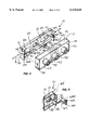
- FIG. 2 is an isometric view of the base shown as it would appear mounted with the wall with the cover shown carried by, and supported away from, the base;
- FIG. 3 is an isometric view of the cover spaced from the base with the hot and neutral leads from the outlet box shown coupled in electrical communication with hot and neutral connector leads of the cover;
- FIG. 4 is an isometric view of the cover shown as it would appear carried by the base.
- FIG. 5 is a fragmented perspective view of the base of FIG. 1 and an engagement element for detachably securing the cover with the base, the engagement element shown spaced from the base.
- the present invention provides, among other things, a new and improved fixture housing and method of installing an electrical fixture. Ensuing embodiments of the invention are easy to construct, easy to implement with existing electrical fixture apparatus and greatly increase the ease and efficiency of installing electrical fixtures.
- FIG. 1 illustrating an exploded isometric view of an electrical fixture 10.
- Electrical fixture 10 is generally of a type for mounting against a wall and for supporting one or more conventional light bulbs such that when energized with electrical energy will illuminate a desired space.
- Electrical fixture comprises a housing 11 including a base 12 and a cover 13, electrical fixture 10 shown as it would appear spaced from a wall 14 having an outlet box 15 including hot and neutral leads, 16 and 17, each of which are generally intended to collectively define an electrical power source.
- Base 12 comprises a plate 20 having an upper edge 21, a lower edge 22, a first end 23 and a second end 24.
- a first extension 25 extends outwardly from plate 20 adjacent first end 23 and a second extension 26 extends outwardly from plate 20 adjacent second end 24.
- First and second extensions 25 and 26 are carried by plate 20 in spaced-apart and substantially opposing relation defining substantially parallel planes.
- Plate 20 also carries a receptacle 30.
- receptacle 30 comprises one or more of plurality of slots each being designated by the reference character 31.
- Each one of the plurality of slots 31 is shown carried by one of first and second extensions 25 and 26, although each one of slots 31 may be carried by plate 20 at other locations.
- each slot 31 extends inwardly into one of first and second extensions 25 and 26 in a direction generally from upper edge 21.
- Cover 13 comprises a body 40 including a continuous sidewall 41 having a closed end 42 and an open end 43 defined generally by a substantially continuous free edge 44 of body 40 opposite closed end 42.
- Cover 13 further includes hot and neutral connector leads 45 and 46.
- hot and neutral connector leads 45 are coupled to sockets 47 carried by closed end 42 of body 40 in series, one of the sockets 47 shown as it would appear carrying or otherwise accommodating, such as by threaded engagement, a light bulb 48 in accordance with conventional light fixtures.
- Electrical fixture 10 may be mounted in electrical communication with a conventional outlet box for providing illumination to a desired space.
- Base 12 serves as the underlying support for electrical fixture 10 and must, therefore, be installed apart from cover 13, after which cover 13 may be coupled in electrical communication with outlet box 15 and subsequently mounted to base 12. With base 12 so installed, hot and neutral leads 16 and 17 may be passed through base 12, such as through opening 49 (shown in FIGS. 1 and 2), to be made available for electrical interconnection with cover 13 as clearly shown in FIG. 2.
- cover 13 may be grasped and, with free edge 44 facing receptacle 30, portions of continuous sidewall 41 inserted into receptacle 30 and, more particularly, into one of slots 30 or both of slots 30 as substantially shown in FIG. 2. So inserted into receptacle 30 defining a second position of cover 13, cover 13 is supported or held outwardly or otherwise away from base 12 leaving base 12 largely exposed. With cover 13 so supported by receptacle 30, a user may couple hot and neutral leads 16 and 17 in electrical communication with hot and neutral connector leads 45 and 46, respectively, via wire nuts 55 and 56 as shown or other suitable mechanical wire connector without having to attend to cover 13. With cover 13 coupled in electrical communication with outlet box 15, cover 13 may be grasped and removed from receptacle 30 as shown in FIG. 3 and then secured to substantially enclose base 12 as shown in FIG. 4 in a normal first position of cover 13.
- engagement apparatus 58 comprising an engagement assembly 60 carried by base 12 and a detachably engagable complemental engagement assembly 61 carried by cover 13.
- engagement assembly 60 comprise a first pin 62 mounted adjacent first extension 25 for movement in reciprocal directions through an opening 62A carried by first extension 25 as generally indicated by the double arrowed line A between first inward and normal second outward positions, and a second pin 63 (FIG. 5) mounted adjacent second extension 26 for movement in reciprocal directions through an opening 63A (shown only in FIG. 5) carried by second extension 26 as generally indicated by the double arrowed line B between first inward and second outward positions.
- Springs, 66 and 67 carried by base 12 support first and second pins 62 and 63, respectively, and normally bias first and second pins 62 and 63 in the second outward positions, respectively.
- Springs 66 and 67 may each be constructed of plastic, metal or other material having shape memory characteristics for normally biasing first and second pins 62 and 63 each in the second outward position.
- complemental engagement assembly 61 comprises first and second apertures 70 and 71 carried by continuous sidewall 41 in spaced-apart and substantially opposing relation, each of which detachably receives therethrough one of first and second pins 62 and 63 for facilitating the detachable engagement of cover 13 with base in the normal first position shown in FIG. 4.
- a user may engage and move first and second pins 62 and 63 inwardly, present cover 13 onto base 12 to capture first and second pins 62 and 63 against continuous sidewall 41, and then maneuver cover 13 onto base 12 to substantially engulf it as shown in FIG. 4 and permit first and second pins 62 and 63 each to snap receive into and through one of first and second apertures 70 and 71 to capture and detachably retain cover 13 with base 12.
- first and second pins 62 and 63 each to snap receive into and through one of first and second apertures 70 and 71 to capture and detachably retain cover 13 with base 12.
Landscapes
- Engineering & Computer Science (AREA)
- General Engineering & Computer Science (AREA)
- Architecture (AREA)
- Connector Housings Or Holding Contact Members (AREA)
Abstract
Description
Claims (26)
Priority Applications (3)
| Application Number | Priority Date | Filing Date | Title |
|---|---|---|---|
| US09/193,930 US6135618A (en) | 1998-11-17 | 1998-11-17 | Electrical fixture and method of installing an electrical fixture |
| US09/357,496 US6259025B1 (en) | 1998-11-17 | 1999-07-20 | Electrical fixture and method of installing an electrical fixture |
| US09/798,145 US6392146B1 (en) | 1998-11-17 | 2001-03-02 | Electrical fixture and method of installing an electrical fixture |
Applications Claiming Priority (1)
| Application Number | Priority Date | Filing Date | Title |
|---|---|---|---|
| US09/193,930 US6135618A (en) | 1998-11-17 | 1998-11-17 | Electrical fixture and method of installing an electrical fixture |
Related Child Applications (1)
| Application Number | Title | Priority Date | Filing Date |
|---|---|---|---|
| US09/357,496 Continuation-In-Part US6259025B1 (en) | 1998-11-17 | 1999-07-20 | Electrical fixture and method of installing an electrical fixture |
Publications (1)
| Publication Number | Publication Date |
|---|---|
| US6135618A true US6135618A (en) | 2000-10-24 |
Family
ID=22715607
Family Applications (1)
| Application Number | Title | Priority Date | Filing Date |
|---|---|---|---|
| US09/193,930 Expired - Lifetime US6135618A (en) | 1998-11-17 | 1998-11-17 | Electrical fixture and method of installing an electrical fixture |
Country Status (1)
| Country | Link |
|---|---|
| US (1) | US6135618A (en) |
Cited By (47)
| Publication number | Priority date | Publication date | Assignee | Title |
|---|---|---|---|---|
| US6259025B1 (en) * | 1998-11-17 | 2001-07-10 | Air Cool Industrial Co., Ltd | Electrical fixture and method of installing an electrical fixture |
| WO2001061242A1 (en) * | 2000-02-15 | 2001-08-23 | Lighting By Branford, Llc | Light fixture and mounting system |
| USD530811S1 (en) | 2005-10-26 | 2006-10-24 | Air Cool Industrial Co., Ltd. | Combination ceiling fan housing and light fixture |
| USD531722S1 (en) | 2005-10-26 | 2006-11-07 | Air Cool Industrial Co., Ltd. | Ceiling fan blade |
| USD532901S1 (en) | 2005-10-26 | 2006-11-28 | Air Cool Industrial Co., Ltd. | Ceiling fan blade holder |
| USD533267S1 (en) | 2005-12-08 | 2006-12-05 | Air Cool Industrial Co., Ltd. | Ceiling fan blade holder |
| USD536466S1 (en) | 2005-12-08 | 2007-02-06 | Air Cool Industrial Co., Ltd. | Ceiling fan light kit |
| USD539896S1 (en) | 2005-12-07 | 2007-04-03 | Air Cool Industrial Co., Ltd. | Ceiling fan housing |
| USD541409S1 (en) | 2006-05-25 | 2007-04-24 | Landmark Enterprise, Inc. | Combined ceiling fan housing, blade irons, and light kit unit |
| USD541410S1 (en) | 2006-05-25 | 2007-04-24 | Landmark Enterprise, Inc. | Combined ceiling fan housing, and blade iron |
| USD543268S1 (en) | 2006-05-25 | 2007-05-22 | Landmark Enterprise, Inc. | Combined ceiling fan housing and light fixture |
| USD543302S1 (en) | 2006-05-25 | 2007-05-22 | Landmark Enterprise, Inc. | Ceiling fan light kit |
| USD545422S1 (en) | 2006-08-09 | 2007-06-26 | Air Cool Industrial Co., Ltd. | Ceiling fan |
| USD546439S1 (en) | 2006-08-09 | 2007-07-10 | Air Cool Industrial Co., Ltd. | Ceiling fan blade holder |
| USD546936S1 (en) | 2006-05-25 | 2007-07-17 | Landmark Enterprise Inc. | Combined ceiling fan housing and light fixture |
| USD547435S1 (en) | 2006-07-13 | 2007-07-24 | Landmark Enterprise Inc. | Combined lower portion of a ceiling fan motor housing and blade holders unit |
| USD547857S1 (en) | 2006-07-18 | 2007-07-31 | Landmark Enterprise Inc. | Combined ceiling fan motor housing and blade holders unit |
| USD552777S1 (en) | 2005-12-08 | 2007-10-09 | Air Cool Industrial Co., Ltd. | Combined ceiling fan and light kit |
| WO2007112535A1 (en) | 2006-04-03 | 2007-10-11 | Tyco Safety Products Canada Ltd. | Methods and apparatus to facilitate component installation |
| USD554250S1 (en) | 2006-07-13 | 2007-10-30 | Landmark Enterprise, Inc. | Combined ceiling fan motor housing, blade holders, and light unit |
| USD554251S1 (en) | 2006-07-13 | 2007-10-30 | Landmark Enterprise, Inc. | Ceiling fan blade holder |
| EP1450592A3 (en) * | 2003-02-21 | 2008-02-06 | ORION ELECTRIC CO., Ltd. | Cover support structure of shield case |
| USD564651S1 (en) | 2007-08-22 | 2008-03-18 | Air Cool Industrial Co., Ltd. | Ceiling fan motor housing |
| USD564652S1 (en) | 2007-08-22 | 2008-03-18 | Air Cool Industrial Co., Ltd. | Ceiling fan blade holder |
| USD565221S1 (en) | 2007-08-22 | 2008-03-25 | Air Cool Industrial Co., Ltd. | Ceiling fan light unit |
| USD569964S1 (en) | 2007-08-17 | 2008-05-27 | Air Cool Industrial Co., Ltd. | Ceiling fan blade holder |
| USD570022S1 (en) | 2007-08-17 | 2008-05-27 | Air Cool Industrial Co., Ltd. | Ceiling fan light unit with a light shade |
| USD571452S1 (en) | 2007-08-17 | 2008-06-17 | Air Cool Industrial Co., Ltd. | Ceiling fan motor housing |
| USD573243S1 (en) | 2007-12-07 | 2008-07-15 | Air Cool Industrial Co., Ltd. | Ceiling fan |
| USD573245S1 (en) | 2007-12-07 | 2008-07-15 | Air Cool Industrial Co., Ltd. | Ceiling fan blade holder |
| USD573242S1 (en) | 2007-12-04 | 2008-07-15 | Air Cool Industrial Co., Ltd. | Combined ceiling fan and light fixture |
| USD573737S1 (en) | 2006-07-13 | 2008-07-22 | Landmark Enterprise, Inc. | Ceiling fan light unit |
| USD578636S1 (en) | 2007-12-04 | 2008-10-14 | Air Cool Industrial Co., Ltd. | Ceiling fan blade holder |
| USD593194S1 (en) | 2007-12-04 | 2009-05-26 | Air Cool Industrial Co., Ltd. | Ceiling fan |
| USD599461S1 (en) | 2009-01-21 | 2009-09-01 | Air Cool Industrial Co., Ltd. | Ceiling fan |
| USD599493S1 (en) | 2009-01-21 | 2009-09-01 | Air Cool Industrial Co., Ltd. | Ceiling fan light kit |
| USD599460S1 (en) | 2009-01-21 | 2009-09-01 | Air Cool Industrial Co., Ltd. | Ceiling fan |
| USD599469S1 (en) | 2009-01-22 | 2009-09-01 | Air Cool Industrial Co., Ltd. | Ceiling fan blade iron |
| USD599470S1 (en) | 2009-01-29 | 2009-09-01 | Air Cool Industrial Co., Ltd. | Ceiling fan blade iron |
| USD599468S1 (en) | 2009-01-21 | 2009-09-01 | Air Cool Industrial Co., Ltd. | Ceiling fan motor housing |
| USD599901S1 (en) | 2009-01-22 | 2009-09-08 | Air Cool Industrial Co., Ltd. | Ceiling fan blade iron |
| USD600339S1 (en) | 2009-02-11 | 2009-09-15 | Air Cool Industrial Co., Ltd. | Ceiling fan |
| USD603035S1 (en) | 2009-01-29 | 2009-10-27 | Air Cool Industrial Co., Ltd. | Combined ceiling fan and light kit |
| US20150029708A1 (en) * | 2013-07-24 | 2015-01-29 | Radiant Opto-Electronics Corporation | Lighting system that can change light emitting characteristic and lighting device and lamp holder of the lighting system |
| US20150062932A1 (en) * | 2013-08-29 | 2015-03-05 | Leotek Electronics Corporation | Lighting device installation method and lighting system |
| US20160280452A1 (en) * | 2015-03-27 | 2016-09-29 | Larry Schultz | Stringed Seasonal Light Storage Device |
| US9869457B1 (en) * | 2015-01-13 | 2018-01-16 | Cooper Technologies Company | Wall pack luminaire with hanging features for installation |
Citations (9)
| Publication number | Priority date | Publication date | Assignee | Title |
|---|---|---|---|---|
| US2804986A (en) * | 1956-02-24 | 1957-09-03 | Jerrold Electronics Corp | Panel box |
| US3018363A (en) * | 1961-03-27 | 1962-01-23 | Gibson Mfg Company | Lighting fixture |
| US3622029A (en) * | 1969-05-12 | 1971-11-23 | Ware Fuse Corp | Electrical outlet box |
| US4415957A (en) * | 1981-02-13 | 1983-11-15 | Square D Company | Patient light with hanger and hinge arrangement for removal without tools |
| US4546419A (en) * | 1984-11-05 | 1985-10-08 | Johnson Kelli J | Wall receptacle recessed box contained light intensity on/off controlled night light system |
| US4893221A (en) * | 1989-07-19 | 1990-01-09 | Friedman Arthur S | Portable light |
| US4924349A (en) * | 1988-05-09 | 1990-05-08 | Lutron Electronics Co., Inc. | Face plate assembly for electrical devices |
| US4941071A (en) * | 1989-02-07 | 1990-07-10 | Steelcase, Inc. | Quick mounting arrangement for light fixtures in overhead cabinets and the like |
| US5816687A (en) * | 1996-10-01 | 1998-10-06 | Tapp; F. Barry | Method and apparatus for hanging Christmas lights |
-
1998
- 1998-11-17 US US09/193,930 patent/US6135618A/en not_active Expired - Lifetime
Patent Citations (9)
| Publication number | Priority date | Publication date | Assignee | Title |
|---|---|---|---|---|
| US2804986A (en) * | 1956-02-24 | 1957-09-03 | Jerrold Electronics Corp | Panel box |
| US3018363A (en) * | 1961-03-27 | 1962-01-23 | Gibson Mfg Company | Lighting fixture |
| US3622029A (en) * | 1969-05-12 | 1971-11-23 | Ware Fuse Corp | Electrical outlet box |
| US4415957A (en) * | 1981-02-13 | 1983-11-15 | Square D Company | Patient light with hanger and hinge arrangement for removal without tools |
| US4546419A (en) * | 1984-11-05 | 1985-10-08 | Johnson Kelli J | Wall receptacle recessed box contained light intensity on/off controlled night light system |
| US4924349A (en) * | 1988-05-09 | 1990-05-08 | Lutron Electronics Co., Inc. | Face plate assembly for electrical devices |
| US4941071A (en) * | 1989-02-07 | 1990-07-10 | Steelcase, Inc. | Quick mounting arrangement for light fixtures in overhead cabinets and the like |
| US4893221A (en) * | 1989-07-19 | 1990-01-09 | Friedman Arthur S | Portable light |
| US5816687A (en) * | 1996-10-01 | 1998-10-06 | Tapp; F. Barry | Method and apparatus for hanging Christmas lights |
Cited By (53)
| Publication number | Priority date | Publication date | Assignee | Title |
|---|---|---|---|---|
| US6392146B1 (en) * | 1998-11-17 | 2002-05-21 | Air Cool Industrial Co. Ltd. | Electrical fixture and method of installing an electrical fixture |
| US6259025B1 (en) * | 1998-11-17 | 2001-07-10 | Air Cool Industrial Co., Ltd | Electrical fixture and method of installing an electrical fixture |
| WO2001061242A1 (en) * | 2000-02-15 | 2001-08-23 | Lighting By Branford, Llc | Light fixture and mounting system |
| EP1450592A3 (en) * | 2003-02-21 | 2008-02-06 | ORION ELECTRIC CO., Ltd. | Cover support structure of shield case |
| USD530811S1 (en) | 2005-10-26 | 2006-10-24 | Air Cool Industrial Co., Ltd. | Combination ceiling fan housing and light fixture |
| USD531722S1 (en) | 2005-10-26 | 2006-11-07 | Air Cool Industrial Co., Ltd. | Ceiling fan blade |
| USD532901S1 (en) | 2005-10-26 | 2006-11-28 | Air Cool Industrial Co., Ltd. | Ceiling fan blade holder |
| USD539896S1 (en) | 2005-12-07 | 2007-04-03 | Air Cool Industrial Co., Ltd. | Ceiling fan housing |
| USD552777S1 (en) | 2005-12-08 | 2007-10-09 | Air Cool Industrial Co., Ltd. | Combined ceiling fan and light kit |
| USD536466S1 (en) | 2005-12-08 | 2007-02-06 | Air Cool Industrial Co., Ltd. | Ceiling fan light kit |
| USD533267S1 (en) | 2005-12-08 | 2006-12-05 | Air Cool Industrial Co., Ltd. | Ceiling fan blade holder |
| WO2007112535A1 (en) | 2006-04-03 | 2007-10-11 | Tyco Safety Products Canada Ltd. | Methods and apparatus to facilitate component installation |
| EP2008504A4 (en) * | 2006-04-03 | 2010-05-19 | Tyco Safety Products Canada Ltd | Methods and apparatus to facilitate component installation |
| USD543302S1 (en) | 2006-05-25 | 2007-05-22 | Landmark Enterprise, Inc. | Ceiling fan light kit |
| USD580044S1 (en) | 2006-05-25 | 2008-11-04 | Air Cool Industrial Co., Ltd. | Ceiling fan blade |
| USD546936S1 (en) | 2006-05-25 | 2007-07-17 | Landmark Enterprise Inc. | Combined ceiling fan housing and light fixture |
| USD541409S1 (en) | 2006-05-25 | 2007-04-24 | Landmark Enterprise, Inc. | Combined ceiling fan housing, blade irons, and light kit unit |
| USD543268S1 (en) | 2006-05-25 | 2007-05-22 | Landmark Enterprise, Inc. | Combined ceiling fan housing and light fixture |
| USD541410S1 (en) | 2006-05-25 | 2007-04-24 | Landmark Enterprise, Inc. | Combined ceiling fan housing, and blade iron |
| USD547435S1 (en) | 2006-07-13 | 2007-07-24 | Landmark Enterprise Inc. | Combined lower portion of a ceiling fan motor housing and blade holders unit |
| USD573737S1 (en) | 2006-07-13 | 2008-07-22 | Landmark Enterprise, Inc. | Ceiling fan light unit |
| USD554250S1 (en) | 2006-07-13 | 2007-10-30 | Landmark Enterprise, Inc. | Combined ceiling fan motor housing, blade holders, and light unit |
| USD554251S1 (en) | 2006-07-13 | 2007-10-30 | Landmark Enterprise, Inc. | Ceiling fan blade holder |
| USD547857S1 (en) | 2006-07-18 | 2007-07-31 | Landmark Enterprise Inc. | Combined ceiling fan motor housing and blade holders unit |
| USD546439S1 (en) | 2006-08-09 | 2007-07-10 | Air Cool Industrial Co., Ltd. | Ceiling fan blade holder |
| USD545422S1 (en) | 2006-08-09 | 2007-06-26 | Air Cool Industrial Co., Ltd. | Ceiling fan |
| USD570022S1 (en) | 2007-08-17 | 2008-05-27 | Air Cool Industrial Co., Ltd. | Ceiling fan light unit with a light shade |
| USD571452S1 (en) | 2007-08-17 | 2008-06-17 | Air Cool Industrial Co., Ltd. | Ceiling fan motor housing |
| USD569964S1 (en) | 2007-08-17 | 2008-05-27 | Air Cool Industrial Co., Ltd. | Ceiling fan blade holder |
| USD565221S1 (en) | 2007-08-22 | 2008-03-25 | Air Cool Industrial Co., Ltd. | Ceiling fan light unit |
| USD564651S1 (en) | 2007-08-22 | 2008-03-18 | Air Cool Industrial Co., Ltd. | Ceiling fan motor housing |
| USD564652S1 (en) | 2007-08-22 | 2008-03-18 | Air Cool Industrial Co., Ltd. | Ceiling fan blade holder |
| USD578636S1 (en) | 2007-12-04 | 2008-10-14 | Air Cool Industrial Co., Ltd. | Ceiling fan blade holder |
| USD593194S1 (en) | 2007-12-04 | 2009-05-26 | Air Cool Industrial Co., Ltd. | Ceiling fan |
| USD573242S1 (en) | 2007-12-04 | 2008-07-15 | Air Cool Industrial Co., Ltd. | Combined ceiling fan and light fixture |
| USD573243S1 (en) | 2007-12-07 | 2008-07-15 | Air Cool Industrial Co., Ltd. | Ceiling fan |
| USD573245S1 (en) | 2007-12-07 | 2008-07-15 | Air Cool Industrial Co., Ltd. | Ceiling fan blade holder |
| USD599461S1 (en) | 2009-01-21 | 2009-09-01 | Air Cool Industrial Co., Ltd. | Ceiling fan |
| USD599493S1 (en) | 2009-01-21 | 2009-09-01 | Air Cool Industrial Co., Ltd. | Ceiling fan light kit |
| USD599460S1 (en) | 2009-01-21 | 2009-09-01 | Air Cool Industrial Co., Ltd. | Ceiling fan |
| USD599468S1 (en) | 2009-01-21 | 2009-09-01 | Air Cool Industrial Co., Ltd. | Ceiling fan motor housing |
| USD599469S1 (en) | 2009-01-22 | 2009-09-01 | Air Cool Industrial Co., Ltd. | Ceiling fan blade iron |
| USD599901S1 (en) | 2009-01-22 | 2009-09-08 | Air Cool Industrial Co., Ltd. | Ceiling fan blade iron |
| USD599470S1 (en) | 2009-01-29 | 2009-09-01 | Air Cool Industrial Co., Ltd. | Ceiling fan blade iron |
| USD603035S1 (en) | 2009-01-29 | 2009-10-27 | Air Cool Industrial Co., Ltd. | Combined ceiling fan and light kit |
| USD600339S1 (en) | 2009-02-11 | 2009-09-15 | Air Cool Industrial Co., Ltd. | Ceiling fan |
| US20150029708A1 (en) * | 2013-07-24 | 2015-01-29 | Radiant Opto-Electronics Corporation | Lighting system that can change light emitting characteristic and lighting device and lamp holder of the lighting system |
| US9341352B2 (en) * | 2013-07-24 | 2016-05-17 | Radiant Opto-Electronics Corporation | Lighting system that can change light emitting characteristic and lighting device and lamp holder of the lighting system |
| US20150062932A1 (en) * | 2013-08-29 | 2015-03-05 | Leotek Electronics Corporation | Lighting device installation method and lighting system |
| US9086199B2 (en) * | 2013-08-29 | 2015-07-21 | Lite-On Technology Corporation | Lighting device installation method and lighting system |
| US9869457B1 (en) * | 2015-01-13 | 2018-01-16 | Cooper Technologies Company | Wall pack luminaire with hanging features for installation |
| US20160280452A1 (en) * | 2015-03-27 | 2016-09-29 | Larry Schultz | Stringed Seasonal Light Storage Device |
| US9630769B2 (en) * | 2015-03-27 | 2017-04-25 | Larry Schultz | Stringed seasonal light storage device |
Similar Documents
| Publication | Publication Date | Title |
|---|---|---|
| US6135618A (en) | Electrical fixture and method of installing an electrical fixture | |
| US6259025B1 (en) | Electrical fixture and method of installing an electrical fixture | |
| US4403277A (en) | Industrial lighting illumination | |
| US4674015A (en) | Fluorescent light fixture with removable ballast | |
| US5410462A (en) | Modular recessed compact fluorescent lamp fixture | |
| US20030206416A1 (en) | Lighting unit with mounting mechanism | |
| US4535393A (en) | Fluorescent lamp housing | |
| US6283430B1 (en) | Horizontal socket housing assembly | |
| US5463540A (en) | Incandescent to fluorescent light conversion kit | |
| CA2279760C (en) | An adapter and socket assembly for a compact fluorescent lamp | |
| US20070008716A1 (en) | Light fixture retrofitting apparatus and method | |
| MXPA00002756A (en) | Luminaire assembly. | |
| US4161020A (en) | Fluorescent lampholder assembly for circline lamp | |
| US5368495A (en) | Method and adapter for relocating a fluorescent tube in a fixture | |
| US5727868A (en) | Wall mounted battery operated, fluorescent illuminating device | |
| US6017134A (en) | Lamp string holding frame | |
| US5192218A (en) | Lampholder assembly | |
| JP2016110873A (en) | Electrical connection device and lighting equipment using the same | |
| JPH04253175A (en) | Fitting device for electric apparatus | |
| JP3305625B2 (en) | lighting equipment | |
| JP2000100239A (en) | Luminaire installation device | |
| JP3003150B2 (en) | lighting equipment | |
| EP1126212B1 (en) | Emergency luminaire | |
| JP3249969B2 (en) | lighting equipment | |
| KR200282508Y1 (en) | A Installing Structure of Lamp |
Legal Events
| Date | Code | Title | Description |
|---|---|---|---|
| STCF | Information on status: patent grant |
Free format text: PATENTED CASE |
|
| AS | Assignment |
Owner name: AIR COOL INDUSTRIAL CO., LTD., TAIWAN Free format text: ASSIGNMENT OF ASSIGNORS INTEREST;ASSIGNOR:TAI, JEN-LUNG DAVID;REEL/FRAME:011551/0161 Effective date: 20001124 |
|
| FPAY | Fee payment |
Year of fee payment: 4 |
|
| FEPP | Fee payment procedure |
Free format text: PAT HOLDER NO LONGER CLAIMS SMALL ENTITY STATUS, ENTITY STATUS SET TO UNDISCOUNTED (ORIGINAL EVENT CODE: STOL); ENTITY STATUS OF PATENT OWNER: LARGE ENTITY |
|
| REFU | Refund |
Free format text: REFUND - PAYMENT OF MAINTENANCE FEE, 8TH YR, SMALL ENTITY (ORIGINAL EVENT CODE: R2552); ENTITY STATUS OF PATENT OWNER: LARGE ENTITY |
|
| FPAY | Fee payment |
Year of fee payment: 8 |
|
| FPAY | Fee payment |
Year of fee payment: 12 |