US6135573A - 26-type electronic controlled pneumatic conversion block - Google Patents
26-type electronic controlled pneumatic conversion block Download PDFInfo
- Publication number
- US6135573A US6135573A US09/106,697 US10669798A US6135573A US 6135573 A US6135573 A US 6135573A US 10669798 A US10669798 A US 10669798A US 6135573 A US6135573 A US 6135573A
- Authority
- US
- United States
- Prior art keywords
- conversion block
- control valve
- car
- ports
- brake
- Prior art date
- Legal status (The legal status is an assumption and is not a legal conclusion. Google has not performed a legal analysis and makes no representation as to the accuracy of the status listed.)
- Expired - Fee Related
Links
Images

Classifications
-
- B—PERFORMING OPERATIONS; TRANSPORTING
- B60—VEHICLES IN GENERAL
- B60T—VEHICLE BRAKE CONTROL SYSTEMS OR PARTS THEREOF; BRAKE CONTROL SYSTEMS OR PARTS THEREOF, IN GENERAL; ARRANGEMENT OF BRAKING ELEMENTS ON VEHICLES IN GENERAL; PORTABLE DEVICES FOR PREVENTING UNWANTED MOVEMENT OF VEHICLES; VEHICLE MODIFICATIONS TO FACILITATE COOLING OF BRAKES
- B60T13/00—Transmitting braking action from initiating means to ultimate brake actuator with power assistance or drive; Brake systems incorporating such transmitting means, e.g. air-pressure brake systems
- B60T13/10—Transmitting braking action from initiating means to ultimate brake actuator with power assistance or drive; Brake systems incorporating such transmitting means, e.g. air-pressure brake systems with fluid assistance, drive, or release
- B60T13/66—Electrical control in fluid-pressure brake systems
- B60T13/665—Electrical control in fluid-pressure brake systems the systems being specially adapted for transferring two or more command signals, e.g. railway systems
-
- B—PERFORMING OPERATIONS; TRANSPORTING
- B60—VEHICLES IN GENERAL
- B60T—VEHICLE BRAKE CONTROL SYSTEMS OR PARTS THEREOF; BRAKE CONTROL SYSTEMS OR PARTS THEREOF, IN GENERAL; ARRANGEMENT OF BRAKING ELEMENTS ON VEHICLES IN GENERAL; PORTABLE DEVICES FOR PREVENTING UNWANTED MOVEMENT OF VEHICLES; VEHICLE MODIFICATIONS TO FACILITATE COOLING OF BRAKES
- B60T17/00—Component parts, details, or accessories of power brake systems not covered by groups B60T8/00, B60T13/00 or B60T15/00, or presenting other characteristic features
- B60T17/18—Safety devices; Monitoring
- B60T17/22—Devices for monitoring or checking brake systems; Signal devices
- B60T17/228—Devices for monitoring or checking brake systems; Signal devices for railway vehicles
Definitions
- the present invention relates, in general, to railway vehicle brake equipment and, more particularly, the present invention is directed to a system which allows for the conversion of porting to an electronic controlled pneumatic portion for train braking systems.
- the present invention is directed to a system which allows for the conversion of 26 porting to an electronic controlled pneumatic portion for 26-Type train braking systems.
- the present invention also provides a means for accessing the necessary porting involved with doing a single car test within a braking arrangement, particularly, within a 26-Type braking arrangement. This means for accessing the necessary porting for performing a single car test can also be used in a remote mounting arrangement on a laminated system setup.
- a "26-L" air brake system is an equipment package which has been designed to meet present day train handling requirements. This system uses air, under pressure, for the braking of locomotives and trailing freight or passenger vehicles. This system has been designed and developed by the Westinghouse Airbrake Company (WABCO), the assignees of the present invention.
- WABCO Westinghouse Airbrake Company
- a "26-L” system can include either a “26-C” air brake control valve or a “26-F” air brake control valve as the primary controlling device in this equipment arrangement. These valves provide the manual means for initiating air brake application and releases.
- the "26-C” valve is used for passenger locomotives and cars.
- the "26-F” valve is used for locomotives which haul freight.
- the present invention can be applied to either the "26-C” or the “26-F” system and thus the term 26-Type is meant to encompass either of these braking systems.
- the 26-Type braking system relies on the transfer of air down the train, which propagates at a certain time frame, to achieve stopping of the train.
- This type of braking system has several disadvantages.
- One disadvantage of the system is the requirement of the train to have a long enough stopping distance to compensate for the time it takes for the air to be transferred down the train.
- care must be taken to ensure that the air supply has been sufficiently replenished after a brake application or a series of brake applications prior to another brake application.
- this currently used 26-Type braking system is limited in the number of units that may be placed within a train consist because of the system's inability to react quickly to reductions at the lead unit over long distances.
- a system for electronically controlling the pneumatics of the 26-Type braking system which overcomes the disadvantages of the currently used 26-Type braking systems is the subject of the aforementioned co-pending application entitled "26-Type Electronic Controlled Pneumatics".
- the present invention is directed to a conversion block which provides access to this porting to allow for electronic controlled braking of 26-Type braking systems.
- the present invention provides a single car automated test arrangement, as part of the conversion block, for systems that are mounted in a laminated arrangement.
- the conversion block of the invention provides a means of accessing 26-Type porting from a remotely mounted location, through pipe or related tubing.
- An object of the present invention is to provide a means for allowing porting to be converted to an electronic controlled pneumatic portion.
- the present invention is particularly directed to converting 26 porting for 26-Type train braking systems.
- Another object of the present invention is to provide a means for accessing 26-Type porting from a remotely mounted location, through pipe or related tubing.
- the conversion block of the present invention achieves these objects by connecting ports from an access plate and allowing air from this access plate to be transferred to a standard electronic unit.
- the primary function of this electronic controlled unit is to make brake applications.
- the conversion block will allow for access to the following porting through the access plate: control reservoir, auxiliary reservoir, brake pipe, 16 pipe, 10 pipe, and 16 pipe release.
- Another object of the present invention is to provide a means for accessing the necessary porting involved with doing a single car test for a remote mounting arrangement in a laminated system setup for a 26-Type braking system. This object is accomplished by providing hook-ups directly on the conversion block in an easily accessible location. This will allow an operator to test the braking feature of the control valve of a single car.
- the conversion block of the present invention provides access to porting to allow all of the advantages of electronic controlled pneumatic braking to take effect including shorter stopping distances, system performance feedback, and continuous recharging features.
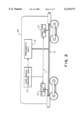
- FIG. 1 shows an overview of an intratrain communication system for the movement of information throughout a train consist.
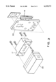
- FIG. 2 shows an overview of an electronic controlled pneumatic passenger car system.
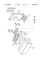
- FIG. 3 shows a conversion block arrangement of the present invention which is to be used in an electronic controlled pneumatic braking system.
- FIG. 4 shows a conversion block arrangement of the present invention for use in a remote mounting arrangement on a laminated system setup which is to be used in an electronic controlled pneumatic braking arrangement.
- FIG. 1 shows an intratrain communication system for the movement of information throughout a train consist 25 comprising a locomotive 27 having a locomotive brake control valve 28 and a plurality of cars 30, at least one of which includes an electronic controlled pneumatic (ECP) car control unit 29.
- the locomotive brake control valve 28 feeds communication signals to the car brake control unit 14 via an intratrain communication system 11.
- This intratrain communication system communicates information, such as a brake application or brake release command, via radio or electric current signals or any well known communicating means.
- the present invention is directed to a conversion block which is one part of the entire unit that allows access to 26-type equipment for the purpose of overlaying features with an electronic controlled pneumatic braking system.
- FIG. 2 shows a single passenger car 30 within a train consist including the individual components for electronically controlling the air brake cylinders of the car.
- each car 30 within the train consist 25 will include these components, however, this system may be designed such that these components would not be required on every car. This may be the case, for example, on cars which are connected together in a semi-permanent manner and would only be disconnected for repairs.
- the car 30 includes trainline or intratrain communication means 11 for transmitting at least brake application and/or brake release communications down the train. Note that other types of communications may be transmitted along this intratrain communication means.
- junction boxes 12 are located at each end of the car 30 to receive at least these brake application and/or brake release communications from the intratrain communication line 11 and to convert these communication signals to an acceptable input level, such as by dropping the voltage level, so that they may be fed to the ECP (electronic controlled pneumatic) car control unit 13.
- the ECP car control unit 13 may also be referred to as the central control unit. This unit holds the software for controlling the pneumatic unit or valve 14 as well as many electronics transfer features for the system.
- the pneumatic unit 14 contains electropneumatic and pneumatic valves which react to the electronic signals sent from the ECP car control unit 13 and delivers the final input pressure via the brake pipe 15 to the car brake cylinders, based upon this signal.
- the electronic controlled pneumatic braking system may be applied to either a standard braking system or to a relayed system.
- a relayed system requires the provision of a relay valve 21, such as a J-Relay, to discharge the output pressure from the pneumatics unit or valve 14 to the brake cylinder, whereas in a standard system, the output pressure is fed directly from the pneumatics valve 14.
- a relayed system is used when longer cars are used in the train.
- FIG. 3 shows a conversion block arrangement of the present invention which is to be used in an electronic controlled pneumatic braking system.
- a standard electronics box assembly or an electronic control unit 20 is connected to a conversion block 17. It is the standard electronic box assembly 20 which allows for electronic control of the brake application.
- the conversion block 17 is also connected to an access plate 22.
- the access plate 22, also referred to as an adapter plate, provides access to the porting for the control reservoir, the auxiliary reservoir, the brake pipe, the 16 pipe, the 10 pipe, and the 16 pipe release.
- the conversion block 17 converts these ports from the access plate 22 to the electronics box assembly 20.
- the access plate 22 also provides a means to access the necessary porting involved with doing a single car test of the car braking equipment.
- a cover plate is removed from a side of the access plate 22 to expose porting 18 from which a single car test device can be hooked-up to the access plate 22.
- FIG. 4 shows a conversion block arrangement of the present invention for use in a remote mounting arrangement on a laminated system setup.
- Components having identical functions as have been described in FIG. 3 will be represented by the same reference numeral.
- FIG. 4 shows pipe or tubing 19 between the conversion block 17 and the access or adapter plate 22. Through this piping or tubing 19, the access plate can facilitate connections with other apparatuses which are not directly connected to the unit.
- the conversion block 17 enables the conversion of these ports to the electronics box assembly 20.
- the conversion block 17 provides a means for accessing porting 18 required to do single car brake testing of the equipment.
- a cover plate is removed from a side of the conversion block 17 to expose porting 18 from which a single car test device can be hooked up and a test of the braking features of the car control valve can be completed.
- the conversion block of the present invention provides access to porting to allow for electronic control of 26-Type braking systems.
- Electronic control of 26-Type braking systems has advantages over currently used 26-Type braking systems in that it allows for an almost instantaneous application of the brakes to all of the units in the train consist, thus reducing stopping distances.
- the 26-Electronic Controlled Pneumatics (ECP) system also creates a replenishable supply source of air since the transfer medium is through the electronics and not the pneumatics.
- Another advantage of electronic controlled pneumatics of the 26-Type braking systems is that it allows for trainline communication features to be built into the system. Also, an unlimited number of units may be placed within a train consist as the electronic communication capabilities of the system would allow for the units to react quickly to a reduction at the lead unit. This would result in significant economic advantages.
Landscapes
- Engineering & Computer Science (AREA)
- Transportation (AREA)
- Mechanical Engineering (AREA)
- Braking Systems And Boosters (AREA)
- Valves And Accessory Devices For Braking Systems (AREA)
- Hydraulic Control Valves For Brake Systems (AREA)
Priority Applications (2)
| Application Number | Priority Date | Filing Date | Title |
|---|---|---|---|
| US09/106,697 US6135573A (en) | 1998-06-29 | 1998-06-29 | 26-type electronic controlled pneumatic conversion block |
| CA002244638A CA2244638C (fr) | 1998-06-29 | 1998-08-10 | De pneumatique de conversion electronique de type 26 |
Applications Claiming Priority (1)
| Application Number | Priority Date | Filing Date | Title |
|---|---|---|---|
| US09/106,697 US6135573A (en) | 1998-06-29 | 1998-06-29 | 26-type electronic controlled pneumatic conversion block |
Publications (1)
| Publication Number | Publication Date |
|---|---|
| US6135573A true US6135573A (en) | 2000-10-24 |
Family
ID=22312787
Family Applications (1)
| Application Number | Title | Priority Date | Filing Date |
|---|---|---|---|
| US09/106,697 Expired - Fee Related US6135573A (en) | 1998-06-29 | 1998-06-29 | 26-type electronic controlled pneumatic conversion block |
Country Status (2)
| Country | Link |
|---|---|
| US (1) | US6135573A (fr) |
| CA (1) | CA2244638C (fr) |
Cited By (4)
| Publication number | Priority date | Publication date | Assignee | Title |
|---|---|---|---|---|
| US20030042788A1 (en) * | 2001-08-31 | 2003-03-06 | Control Chief Corporation | Remote control train-line braking system |
| US20110126732A1 (en) * | 2009-05-20 | 2011-06-02 | New York Air Brake Corporattion | Auxilliary smart power system for ecp equipped train |
| US9616872B2 (en) | 2012-05-08 | 2017-04-11 | Wabtec Holding Corp. | ABDX-C service graduating valve and slide valve and slide valve design incorporating accelerated application valve (AAV) functionality |
| EP4177480A4 (fr) * | 2021-09-24 | 2023-08-09 | Meishan CRRC Brake Science & Technology Co., Ltd. | Dispositif de conversion, système de freinage et train |
Families Citing this family (1)
| Publication number | Priority date | Publication date | Assignee | Title |
|---|---|---|---|---|
| CN112572513B (zh) * | 2020-12-15 | 2022-04-01 | 神华铁路装备有限责任公司 | 交通工具及制动系统 |
Citations (4)
| Publication number | Priority date | Publication date | Assignee | Title |
|---|---|---|---|---|
| US4659149A (en) * | 1985-11-08 | 1987-04-21 | American Standard Inc. | Cross blending electro-dynamic/friction brake system for multi-car train consist having mixed power and non-power cars |
| US5039940A (en) * | 1990-04-24 | 1991-08-13 | Aeg Westinghouse Transportation Systems, Inc. | Connector for verifying sequence of transit car controls |
| US5564795A (en) * | 1994-06-14 | 1996-10-15 | New York Air Brake Corporation | Electropneumatic brake control system parking brake |
| EP0829402A2 (fr) * | 1996-09-13 | 1998-03-18 | New York Air Brake Corporation | Ensemble modulaire de commande de freinage d'une locomotive |
-
1998
- 1998-06-29 US US09/106,697 patent/US6135573A/en not_active Expired - Fee Related
- 1998-08-10 CA CA002244638A patent/CA2244638C/fr not_active Expired - Fee Related
Patent Citations (4)
| Publication number | Priority date | Publication date | Assignee | Title |
|---|---|---|---|---|
| US4659149A (en) * | 1985-11-08 | 1987-04-21 | American Standard Inc. | Cross blending electro-dynamic/friction brake system for multi-car train consist having mixed power and non-power cars |
| US5039940A (en) * | 1990-04-24 | 1991-08-13 | Aeg Westinghouse Transportation Systems, Inc. | Connector for verifying sequence of transit car controls |
| US5564795A (en) * | 1994-06-14 | 1996-10-15 | New York Air Brake Corporation | Electropneumatic brake control system parking brake |
| EP0829402A2 (fr) * | 1996-09-13 | 1998-03-18 | New York Air Brake Corporation | Ensemble modulaire de commande de freinage d'une locomotive |
Cited By (5)
| Publication number | Priority date | Publication date | Assignee | Title |
|---|---|---|---|---|
| US20030042788A1 (en) * | 2001-08-31 | 2003-03-06 | Control Chief Corporation | Remote control train-line braking system |
| US7494194B2 (en) * | 2001-08-31 | 2009-02-24 | Control Chief Corporation | Remote control train-line braking system |
| US20110126732A1 (en) * | 2009-05-20 | 2011-06-02 | New York Air Brake Corporattion | Auxilliary smart power system for ecp equipped train |
| US9616872B2 (en) | 2012-05-08 | 2017-04-11 | Wabtec Holding Corp. | ABDX-C service graduating valve and slide valve and slide valve design incorporating accelerated application valve (AAV) functionality |
| EP4177480A4 (fr) * | 2021-09-24 | 2023-08-09 | Meishan CRRC Brake Science & Technology Co., Ltd. | Dispositif de conversion, système de freinage et train |
Also Published As
| Publication number | Publication date |
|---|---|
| CA2244638C (fr) | 2002-12-10 |
| CA2244638A1 (fr) | 1999-12-29 |
Similar Documents
| Publication | Publication Date | Title |
|---|---|---|
| US6435624B1 (en) | Railway locomotive brake controller | |
| CN101511656B (zh) | 有线分布式电源的接口系统 | |
| US6163089A (en) | Railway locomotive ECP train line control | |
| AU745119B2 (en) | Method for limiting brake cylinder pressure on locomotives equipped with distributed power and electronic brake systems | |
| US5791744A (en) | Pneumatic trainline control unit | |
| EP1129919A2 (fr) | Dispositif de commande de freinage pour locomotive de chemin de fer | |
| US6839664B1 (en) | Electrically controlled pneumatic end of train pneumatic emulation system | |
| US6189980B1 (en) | Locomotive to ECP brake conversion system | |
| US20050121971A1 (en) | Serial train communication system | |
| MXPA05006155A (es) | Sistemas de frenado neumatico con sistema de interconexion de control neumatico a electrico. | |
| WO1992021541A1 (fr) | Interface pour vehicules a systemes de freinage differents | |
| US6135573A (en) | 26-type electronic controlled pneumatic conversion block | |
| US6158821A (en) | 26-type controlled pneumatic access plate | |
| US6347840B1 (en) | ECP commanded emergencies via a conventional EAB brake controller | |
| CA2243799A1 (fr) | Composants pneumatiques electroniques de type 26 | |
| US6062653A (en) | Brake valve system for dedicated freight cars | |
| JP2004210280A (ja) | リレー弁ベースの急速ブレーキ管作用及び弛めシステム | |
| RU196698U1 (ru) | Электропневматический тормоз грузового вагона | |
| ITTO980726A1 (it) | Sistema frenante, in particolare per convogli ferroviari di elevata composizione. | |
| MXPA98008819A (en) | Method and apparatus for controlling electron pneumatic brakes in trains using an electronic air brake exists | |
| MXPA99011316A (en) | Railway locomotive ecp train line control | |
| HK1030913A (en) | Railway locomotive ecp train line control |
Legal Events
| Date | Code | Title | Description |
|---|---|---|---|
| AS | Assignment |
Owner name: WESTINGHOUSE AIR BRAKE COMPANY, PENNSYLVANIA Free format text: ASSIGNMENT OF ASSIGNORS INTEREST;ASSIGNORS:KUSHNIR, LAWRENCE M., JR.;SANTORO, RALPH JR.;REEL/FRAME:009320/0017;SIGNING DATES FROM 19980625 TO 19980626 |
|
| FEPP | Fee payment procedure |
Free format text: PAYOR NUMBER ASSIGNED (ORIGINAL EVENT CODE: ASPN); ENTITY STATUS OF PATENT OWNER: LARGE ENTITY |
|
| REMI | Maintenance fee reminder mailed | ||
| LAPS | Lapse for failure to pay maintenance fees | ||
| STCH | Information on status: patent discontinuation |
Free format text: PATENT EXPIRED DUE TO NONPAYMENT OF MAINTENANCE FEES UNDER 37 CFR 1.362 |
|
| FP | Lapsed due to failure to pay maintenance fee |
Effective date: 20041024 |